EP0024480A2 - Electric hand tool - Google Patents
Electric hand tool Download PDFInfo
- Publication number
- EP0024480A2 EP0024480A2 EP80102955A EP80102955A EP0024480A2 EP 0024480 A2 EP0024480 A2 EP 0024480A2 EP 80102955 A EP80102955 A EP 80102955A EP 80102955 A EP80102955 A EP 80102955A EP 0024480 A2 EP0024480 A2 EP 0024480A2
- Authority
- EP
- European Patent Office
- Prior art keywords
- hand tool
- electric hand
- display
- housing
- tool according
- Prior art date
- Legal status (The legal status is an assumption and is not a legal conclusion. Google has not performed a legal analysis and makes no representation as to the accuracy of the status listed.)
- Withdrawn
Links
Images
Classifications
-
- B—PERFORMING OPERATIONS; TRANSPORTING
- B25—HAND TOOLS; PORTABLE POWER-DRIVEN TOOLS; MANIPULATORS
- B25F—COMBINATION OR MULTI-PURPOSE TOOLS NOT OTHERWISE PROVIDED FOR; DETAILS OR COMPONENTS OF PORTABLE POWER-DRIVEN TOOLS NOT PARTICULARLY RELATED TO THE OPERATIONS PERFORMED AND NOT OTHERWISE PROVIDED FOR
- B25F5/00—Details or components of portable power-driven tools not particularly related to the operations performed and not otherwise provided for
- B25F5/02—Construction of casings, bodies or handles
-
- B—PERFORMING OPERATIONS; TRANSPORTING
- B23—MACHINE TOOLS; METAL-WORKING NOT OTHERWISE PROVIDED FOR
- B23B—TURNING; BORING
- B23B45/00—Hand-held or like portable drilling machines, e.g. drill guns; Equipment therefor
- B23B45/001—Housing of the drill, e.g. handgrip
-
- B—PERFORMING OPERATIONS; TRANSPORTING
- B23—MACHINE TOOLS; METAL-WORKING NOT OTHERWISE PROVIDED FOR
- B23Q—DETAILS, COMPONENTS, OR ACCESSORIES FOR MACHINE TOOLS, e.g. ARRANGEMENTS FOR COPYING OR CONTROLLING; MACHINE TOOLS IN GENERAL CHARACTERISED BY THE CONSTRUCTION OF PARTICULAR DETAILS OR COMPONENTS; COMBINATIONS OR ASSOCIATIONS OF METAL-WORKING MACHINES, NOT DIRECTED TO A PARTICULAR RESULT
- B23Q1/00—Members which are comprised in the general build-up of a form of machine, particularly relatively large fixed members
- B23Q1/0009—Energy-transferring means or control lines for movable machine parts; Control panels or boxes; Control parts
- B23Q1/0045—Control panels or boxes
-
- B—PERFORMING OPERATIONS; TRANSPORTING
- B25—HAND TOOLS; PORTABLE POWER-DRIVEN TOOLS; MANIPULATORS
- B25B—TOOLS OR BENCH DEVICES NOT OTHERWISE PROVIDED FOR, FOR FASTENING, CONNECTING, DISENGAGING OR HOLDING
- B25B21/00—Portable power-driven screw or nut setting or loosening tools; Attachments for drilling apparatus serving the same purpose
-
- G—PHYSICS
- G09—EDUCATION; CRYPTOGRAPHY; DISPLAY; ADVERTISING; SEALS
- G09F—DISPLAYING; ADVERTISING; SIGNS; LABELS OR NAME-PLATES; SEALS
- G09F9/00—Indicating arrangements for variable information in which the information is built-up on a support by selection or combination of individual elements
Definitions
- the invention is based on an electric hand tool, such as hand-held drilling, milling, sawing machine or the like, according to the preamble of the main claim.
- a plurality of rotary or swivel lever switches are provided, with which the desired operating state can be set. These switches are arranged in the most diverse places on the housing. The respectively set operating state of the electric hand tool can be read from the respective position of the various switches.
- the visual display of an overload by means of the display panel enables full power utilization of the electric hand tool while protecting the electric hand tool and reducing the risk of accidents.
- the display of the overload signals to the user that he is already demanding too much power from the electric hand tool, ie that the overload protection of the electric hand tool will switch off the electric hand tool if this operating state is continued.
- the user can thus reduce the power demanded of the electric hand tool, so that on the one hand this is protected and on the other hand the risk of accidents is eliminated by suddenly switching off the electric hand tool when the overload protection is activated. Damage to the workpieces as a result of unexpected switching off of the electric hand tool can thus also be prevented.
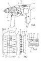
- a display field 15 of a display device 16 (indicated schematically in FIG. 3 by a dash-dotted frame) is arranged on the housing 10.
- the display panel 15 is shown enlarged in FIG. 2. It points a plurality of individual, side by side and one behind the other, spatially limited sections 17. Each row of sections 17 arranged one behind the other is assigned a scale 18 or 19 with characteristic data of the operating state of the hand drill.
- the left scale 18 in FIG. 2 contains speed information in revolutions / min and the right scale 19 in FIG. 2 contains further information about the operating state of the hand drill. "ON" means that the hand drill is switched on / off "1st GEAR" and '2.
- Each of the display panel sections 17 is selectively illuminated by a signal lamp 25 (FIG. 3).
- These signal lamps 25 are arranged directly below the display panel 15 in accordance with its configuration and are preferably designed as light-emitting diodes.
- a control circuit 26 which can be designed as a micro-computer or also as a pure coding circuit, the individual signal lamps 25 are selectively controlled and lit according to the existing operating state of the hand drill. If, for example, the hand drill is switched on, 1st gear is engaged and the drilling spindle 1 'is running clockwise at a speed of 1500 rpm, the sections 17 of the display field 15 which are marked by hatching in FIG. 2 light up. The operator can recognize the operating state by looking at the display panel 15. This is so that the user always has the display field 15 in view even during the work process arranged on the housing top 24 opposite the handle 13 and preferably embedded flush in the housing wall (FIGS. 1 and 3).
Landscapes
- Engineering & Computer Science (AREA)
- Mechanical Engineering (AREA)
- Physics & Mathematics (AREA)
- General Physics & Mathematics (AREA)
- Theoretical Computer Science (AREA)
- Sawing (AREA)
- Machine Tool Sensing Apparatuses (AREA)
- Drilling And Boring (AREA)
- Portable Power Tools In General (AREA)
- Control Of Electric Motors In General (AREA)
Abstract
Es wird ein Elektrohandwerkzeug, wie handgeführte Bohr-, Fräs-, Sägemaschine od. dgl. insbesondere Heimwerker-Kombinationsmaschine angegeben, welches ein erhebliches Maß an Sicherheit und Schutz für Benutzer und Elektrohandwerkzeug bietet und darüber hinaus einen optimalen Einsatz des Elektrohandwerkzeugs beim jeweiligen Arbeitsvorgang ermöglicht. Hierzu ist auf dem Gehäuse (10) ein optisches Anzeigefeld (15; 20) einer Anzeigevorrichtung (16) angeordnet, auf welchem die Kenndaten des jeweiligen Betriebszustands, wie Einschaltung, Rechts- oder Linkslauf, Überlastung, Drehzahl und dgl. abgelesen werden können.An electric hand tool, such as a hand-held drilling, milling, sawing machine or the like, in particular a do-it-yourself combination machine, is specified, which offers a considerable degree of safety and protection for users and electric hand tools and, moreover, enables optimal use of the electric hand tool in the respective work process. For this purpose, an optical display field (15; 20) of a display device (16) is arranged on the housing (10), on which the characteristic data of the respective operating state, such as switching on, clockwise or counterclockwise rotation, overload, speed and the like can be read.
Description
Die Erfindung geht aus von einem Elektrohandwerkzeug, wie handgeführte Bohr-, Fräs-, Sägemaschine od. dgl., nach der Gattung des Hauptanspruchs.The invention is based on an electric hand tool, such as hand-held drilling, milling, sawing machine or the like, according to the preamble of the main claim.
Bei bekannten Elektrohandwerkzeugen dieser Art sind je nach Ausstattung des Elektrohandwerkzeugs eine Vielzahl von Dreh- oder Schwenkhebelschalter vorgesehen, mit welchen der gewünschte Betriebszustand eingestellt werden kann. Diese Schalter sind an den verschiedensten Stellen des Gehäuses angeordnet. Der jeweils eingestellte Betriebszustand des Elektrohandwerkzeugs ist an der jeweiligen Stellung der verschiedenen Schalter abzulesen.In known electric hand tools of this type, depending on the equipment of the electric hand tool, a plurality of rotary or swivel lever switches are provided, with which the desired operating state can be set. These switches are arranged in the most diverse places on the housing. The respectively set operating state of the electric hand tool can be read from the respective position of the various switches.
Bei der Vielzahl der bereits heute angebotenen Einstellmöglichkeiten an einem Elektrohandwerkzeug ist es dem Benutzer häufig unmöglich, die jeweilige Schaltstellung der an verschiedenen Orten des Gehäuses angeordneten Schalter auf einen Blick schnell und rasch zu erfassen, um somit den Betriebszustand des Elektrowerkzeugs zu kontrollieren. Somit passieren aufgrund irrtümlicher Vorstellungen über den Betriebszustand des Elektrowerkzeugs häufig Pannen, die den Benutzer und auch das Elektrohandwerkzeug in seiner Funktion gefährden und zu einer Verschlechterung des Arbeitsergebnisses führen.With the multitude of setting options already available on an electric hand tool, it is often impossible for the user to quickly and quickly grasp the respective switching position of the switches arranged at different locations on the housing in order to control the operating state of the electric tool. Because of erroneous ideas about the operating state of the power tool, breakdowns often occur that endanger the function of the user and also the electric hand tool and lead to a deterioration in the work result.
Das erfindungsgemäße Elektrohandwerkzeug mit den kennzeichnenden Merkmalen des Hauptanspruchs hat demgegenüber den Vorteil, daß dem Benutzer eine ständige optische Überwachung des Betriebszustandes des Elektrohandwerkzeugs ermöglicht wird. Der Benutzer kann während des Ansetzens des Elekrohandwerkzeugs oder gar während des Arbeitsvorgangs mit einem einzigen Blick den Betriebszustand des Elektrohandwerkzeugs feststellen und ständig kontrollieren und auch eine Änderung wahrnehmen. Es kann also z.B. nicht passieren, daß der Benutzer mit einer kleinen Drehzahl zu bohren beabsichtigt und bei Durchführung des Bohrvorgangs plötzlich und unerwartet eine sehr große Drehzahl auftritt, was zur Beschädigung des Elektrohandwerkzeugsoder des zu bearbeitenden Werkstücks führen kann. Dies trägt auch gleichzeitig zur Sicherheit des Benutzers bei, denn z.B. ein Irrtum über die Drehrichtung des Elektromotors kann, z.B. bei Verwendung einer Heimwerker-Kombinationsmaschine als Fräs- oder Sägemaschine, eine erhebliche Gefährdung des Benutzers herbeiführen. Die optische Anzeige einer Überlastung mittels des Anzeigefeldes z.B. ermöglicht eine volle Leistungsausnutzung des Elektrohandwerkzeugs bei gleichzeitiger Schonung des Elektrohandwerkzeugs und Verringerung der Unfallgefahr. Die Anzeige der Überlastung signalisiert dem Benutzer, daß er bereits zuviel Leistung aus dem Elektrohandwerkzeug verlangt, d.h. daß der überlastschutz des Elektrohandwerkzeugs bei Fortsetzung dieses Betriebszustandes das Elektrohandwerkzeug abschalten wird. Der Benutzer kann also die dem Elektrohandwerkzeug abgeforderte Leistung verringern, so daß einerseits dieses geschont und andererseits die Unfallgefahr durch brüskes Abschalten des Elektrohandwerkzeugs beim Ansprechen des Überlastschutzes beseitigt wird. Damit kann zugleich auch eine Beschädigung der Werkstücke infolge unerwarteten Abschaltens des Elektrohandwerkzeugs verhindert werden.The electric hand tool according to the invention with the characterizing features of the main claim has the advantage that the user is able to constantly monitor the operating state of the electric hand tool. The user can determine and continuously control the operating state of the electric hand tool with a single glance during the attachment of the electric hand tool or even during the working process and also perceive a change. For example, it may not happen that the user intends to drill at a low speed and suddenly and unexpectedly a very high speed occurs when the drilling operation is carried out, which can damage the electrical hand tool or the workpiece to be machined. This also contributes to the safety of the user, because, for example, an error about the direction of rotation of the electric motor, for example when using a home improvement combination machine as a milling or sawing machine, can endanger the user considerably bring about. The visual display of an overload by means of the display panel, for example, enables full power utilization of the electric hand tool while protecting the electric hand tool and reducing the risk of accidents. The display of the overload signals to the user that he is already demanding too much power from the electric hand tool, ie that the overload protection of the electric hand tool will switch off the electric hand tool if this operating state is continued. The user can thus reduce the power demanded of the electric hand tool, so that on the one hand this is protected and on the other hand the risk of accidents is eliminated by suddenly switching off the electric hand tool when the overload protection is activated. Damage to the workpieces as a result of unexpected switching off of the electric hand tool can thus also be prevented.
Durch die in den Unteransprüchen aufgeführten Maßnahmen sind vorteilhafte Weiterbildungen und Verbesserungen des im Hauptanspruch angegebenen Elektrohandwerkzeugs möglich.Advantageous further developments and improvements of the electric hand tool specified in the main claim are possible through the measures listed in the subclaims.
Die Erfindung ist anhand von in der Zeichnung dargestellten Ausführungsbeispielen in der nachfolgenden Beschreibung näher erläutert. Dabei zeigen:
- Fig. 1 eine perspektivische Ansicht einer Handbohrmaschine,
- Fig. 2 eine vergrößerte Darstellung einer Draufsicht eines Anzeigefelds einer Anzeigevorrichtung der Handbohrmaschine in Fig. 1,
- Fig. 3 einen Schnitt längs der Linie III - III in Fig. 2 mit schematisch ergänzter Anzeigevorrichtung,
- Fig. 4 eine vergrößerte Darstellung einer Draufsicht eines Anzeigefelds einer Anzeigevorrichtung ge.äß einem zweiten Ausführungsbeispiel.
- 1 is a perspective view of a hand drill,
- FIG. 2 shows an enlarged illustration of a plan view of a display field of a display device of the hand drill in FIG. 1,
- 3 shows a section along the line III-III in FIG. 2 with a schematically supplemented display device,
- Fig. 4 is an enlarged view of a plan view of a display panel of a display device according to a second embodiment.
Die in Fig. 1 als Beispiel eines Elektrohandwerkzeugs dargestellte Handbohrmaschine weist ein Gehäuse 10 auf. Eine aus dem Gehäuse 10 austretende Bohrspindel 11 trägt ein Spannfutter 12 zur Aufnahme eines Bohrers und wird in bekannter Weise von einem nicht dargestellten Elektromotor unter Zwischenschaltung eines ebenfalls nicht gezeigten übersetzungsgetriebes angetrieben. Das Gehäuse 10 trägt an der Unterseite einen angeformten pistolenartigen Handgriff 13. Zur Erleichterung des Bohrvorgangs kann - wie in Fig. 1 dargestellt - am Gehäuse 10 nahe der Austrittsstelle der Bohrspindel 11 noch ein weiterer Handgriff 14 festgeklemmt sein.The hand drill shown in FIG. 1 as an example of an electric hand tool has a
Auf dem Gehäuse 10 ist ein Anzeigefeld 15 einer Anzeigevorrichtung 16 (in Fig. 3 durch strichpunktierte Umrahmung schematisch angedeutet) angeordnet. Das Anzeigefeld 15 ist in Fig. 2 vergrößert dargestellt. Es weist eine Vielzahl von einzelnen, neben- und hintereinander angeordneten,räumlich begrenzten Sektionen 17 auf. Jeder Reihe von hintereinander angeordneten Sektionen 17 ist eine Skala 18 bzw. 19 mit Kenndaten des Betriebszustandes der Handbohrmaschine zugeordnet. Dabei enthält die in Fig. 2 linke Skala 18 Drehzahlangaben in Umdrehungen/min und die in Fig. 2 rechte Skala 19 weitere Angaben über den Betriebszustandder handbohrmaschine Dabei bedeuten "EIN"Ein-/Ausschaltung der Handbohrmaschine "1. GANG" und '2. GANG" eingeschalteter 1. bzw. 2. Gang, "LINKS" und "RECHTS" Links- oder Rechtslauf der Bohrspindel 11, "ÜBERLAST" Warnung bei Überlastung des Elektromotors und "ÜBERPLAST-AUTO" Ansprechen der automatischen Überlastabschaltung.A
Jede der Anzeigefeldsektionen 17 wird von einer Signallampe 25 (Fig. 3) selektiv beleuchtet. Diese Signallampen 25 sind unmittelbar unterhalb des Anzeigefeldes 15 entsprechend dessen Ausgestaltung angeordnet und vorzugsweise als Leuchtdioden ausgebildet. Mittels einer Steuerschaltung 26 , die als Mikro-Computer oder auch als reine Codierschaltung ausgebildet sein kann, werden die einzelnen Signallampen25 entsprechend dem vorhandenen Betriebszustand der Handbohrmaschine selektiv angesteuert und zum Aufleuchten gebracht. Ist z.B. die Handbohrmaschine eingeschaltet, der 1. Gang eingelegt und läuft die Bohrspindel 1' mit einer Crehzahl von 1500 U/min im Rechtslauf, so leuchten die in Fig. 2 durch Schraffur gekennzeichneten Sektionen 17 des Anzeigefeldes 15 auf. Der Bedienende kann mit einem Blick auf das Anzeigefeld 15 den Betriebszustand erkennen. Damit der Benutzer das Anzeigefeld 15 auch während des Arbeitsvorgangs ständig im Blickfeld hat, ist dieses auf der dem Handgriff 13 gegenüberliegenden Gehäuseoberseite 24 angeordnet und vorzugsweise in die Gehäusewand bündig eingelassen (Fig. 1 und 3).Each of the
In Fig. 4 ist ein anders gestaltetes Anzeigefeld 20 gemäß einem weiteren Ausführungsbeispiel dargestellt. Das Anzeigefeld 20.enthält ein 7-Segment-Display 21 sowie eine Symolskala 22, deren Einzelsymbole 23 selektiv, je nach Betriebszustand, beleuchtet werden können. Dieses Anzeigefeld 20 ist in gleicher Weise auf der dem Handgriff 13 gegenüberliegenden Gehäuseoberseite 24 des Gehäuses 10 angeordnet. Das 7-Segment-Display 21 zeigt dem Benutzer die Drehzahl der Bohrspindel 11 an, während durch entsprechendes Aufleuchten einer oder mehrerer der Einzelsymbole der weitere Betriebszustand der Handbohrmaschine-signalisiert wird. So bedeutet "E" das Eingeschaltetsein der Maschine, "←","→" Links- bzw. Rechtslauf der Maschine und das in Fig. 4 rechte Einzelsymbol 23 Uberlastwarnung.4 shows a differently designed
Claims (6)
Applications Claiming Priority (2)
| Application Number | Priority Date | Filing Date | Title |
|---|---|---|---|
| DE19797923500U DE7923500U1 (en) | 1979-08-17 | 1979-08-17 | ELECTRIC HAND TOOL |
| DE7923500U | 1979-08-17 |
Publications (2)
| Publication Number | Publication Date |
|---|---|
| EP0024480A2 true EP0024480A2 (en) | 1981-03-11 |
| EP0024480A3 EP0024480A3 (en) | 1981-07-01 |
Family
ID=6706662
Family Applications (1)
| Application Number | Title | Priority Date | Filing Date |
|---|---|---|---|
| EP80102955A Withdrawn EP0024480A3 (en) | 1979-08-17 | 1980-05-28 | Electric hand tool |
Country Status (5)
| Country | Link |
|---|---|
| US (1) | US4503425A (en) |
| EP (1) | EP0024480A3 (en) |
| JP (1) | JPS5633286A (en) |
| DE (1) | DE7923500U1 (en) |
| ES (1) | ES252570Y (en) |
Cited By (5)
| Publication number | Priority date | Publication date | Assignee | Title |
|---|---|---|---|---|
| FR2517999A1 (en) * | 1981-12-15 | 1983-06-17 | Peugeot Outillage Elect | MULTI-SPEED PORTABLE DRILL |
| FR2531250A1 (en) * | 1982-07-27 | 1984-02-03 | Kioritz Corp | DISPLAY DEVICE FOR PORTABLE MOTOR MACHINE |
| US5725533A (en) * | 1990-03-09 | 1998-03-10 | Nobel Biocare Ab | Torsional tightener for bone anchoring or implant elements/tools |
| EP2747948A4 (en) * | 2011-08-26 | 2016-01-20 | Husqvarna Ab | Guide and control assembly |
| CN112221570A (en) * | 2020-09-30 | 2021-01-15 | 莱芜职业技术学院 | Double-mode electric crushing grinder |
Families Citing this family (6)
| Publication number | Priority date | Publication date | Assignee | Title |
|---|---|---|---|---|
| JPS58151113U (en) * | 1982-04-02 | 1983-10-11 | 株式会社ダイゲン | Pallet stopping device |
| JP2573629B2 (en) * | 1987-10-30 | 1997-01-22 | 石川島播磨重工業株式会社 | Work alignment device |
| JPH085136Y2 (en) * | 1990-03-22 | 1996-02-14 | 株式会社椿本チエイン | 4-way centering device |
| US6595300B2 (en) * | 2001-12-20 | 2003-07-22 | Black & Decker Inc. | Side handles on drill/drivers |
| FR2990548B1 (en) * | 2012-05-11 | 2016-05-27 | Nigen Steve Le | ELECTRICAL MODULE FOR SAFETY AND PORTABLE INFORMATION |
| EP4219082A1 (en) * | 2017-07-31 | 2023-08-02 | Milwaukee Electric Tool Corporation | Rotary power tool |
Citations (3)
| Publication number | Priority date | Publication date | Assignee | Title |
|---|---|---|---|---|
| GB812287A (en) * | 1955-12-08 | 1959-04-22 | Mark Rutter | Improved means for indicating linear and angular measurements |
| FR2092214A5 (en) * | 1970-04-07 | 1971-01-21 | Arnz Friedr Aug Firma | |
| DE2442260A1 (en) * | 1974-09-04 | 1976-03-18 | Bosch Gmbh Robert | CRAFT MACHINE |
Family Cites Families (6)
| Publication number | Priority date | Publication date | Assignee | Title |
|---|---|---|---|---|
| US3626367A (en) * | 1969-12-22 | 1971-12-07 | Bendix Corp | Vehicle subsystem monitors |
| US3895517A (en) * | 1974-01-14 | 1975-07-22 | Jo Line Tools | Electronic torque wrench |
| JPS5127242A (en) * | 1974-08-30 | 1976-03-06 | Komatsu Mfg Co Ltd | Kensetsusharyo no jidoanzenkeihosochi |
| US4126855A (en) * | 1975-05-12 | 1978-11-21 | Afe Industries, Inc. | Annunciator readout unit |
| US4189726A (en) * | 1977-10-27 | 1980-02-19 | Miller Richard L | Automatic orientation circuit indicator device for portable power tools and the like |
| US4254412A (en) * | 1979-06-12 | 1981-03-03 | Powell Industries, Inc. | Controller deviation indicator |
-
1979
- 1979-08-17 DE DE19797923500U patent/DE7923500U1/en not_active Expired
-
1980
- 1980-05-28 EP EP80102955A patent/EP0024480A3/en not_active Withdrawn
- 1980-07-07 US US06/166,458 patent/US4503425A/en not_active Expired - Lifetime
- 1980-08-14 ES ES1980252570U patent/ES252570Y/en not_active Expired
- 1980-08-14 JP JP11116480A patent/JPS5633286A/en active Pending
Patent Citations (3)
| Publication number | Priority date | Publication date | Assignee | Title |
|---|---|---|---|---|
| GB812287A (en) * | 1955-12-08 | 1959-04-22 | Mark Rutter | Improved means for indicating linear and angular measurements |
| FR2092214A5 (en) * | 1970-04-07 | 1971-01-21 | Arnz Friedr Aug Firma | |
| DE2442260A1 (en) * | 1974-09-04 | 1976-03-18 | Bosch Gmbh Robert | CRAFT MACHINE |
Cited By (7)
| Publication number | Priority date | Publication date | Assignee | Title |
|---|---|---|---|---|
| FR2517999A1 (en) * | 1981-12-15 | 1983-06-17 | Peugeot Outillage Elect | MULTI-SPEED PORTABLE DRILL |
| EP0082028A1 (en) * | 1981-12-15 | 1983-06-22 | Peugeot Outillage Electrique, Société dite: | Machine, especially an electric drilling machine |
| FR2531250A1 (en) * | 1982-07-27 | 1984-02-03 | Kioritz Corp | DISPLAY DEVICE FOR PORTABLE MOTOR MACHINE |
| US5725533A (en) * | 1990-03-09 | 1998-03-10 | Nobel Biocare Ab | Torsional tightener for bone anchoring or implant elements/tools |
| EP2747948A4 (en) * | 2011-08-26 | 2016-01-20 | Husqvarna Ab | Guide and control assembly |
| CN112221570A (en) * | 2020-09-30 | 2021-01-15 | 莱芜职业技术学院 | Double-mode electric crushing grinder |
| CN112221570B (en) * | 2020-09-30 | 2021-10-29 | 莱芜职业技术学院 | Double-mode electric crushing grinder |
Also Published As
| Publication number | Publication date |
|---|---|
| JPS5633286A (en) | 1981-04-03 |
| EP0024480A3 (en) | 1981-07-01 |
| DE7923500U1 (en) | 1981-02-19 |
| US4503425A (en) | 1985-03-05 |
| ES252570Y (en) | 1981-05-16 |
| ES252570U (en) | 1980-11-16 |
Similar Documents
| Publication | Publication Date | Title |
|---|---|---|
| DE2926111C2 (en) | ||
| DE2933355A1 (en) | ELECTRIC HAND TOOL | |
| DE10215736B4 (en) | Dip router with electronic depth adjustment | |
| DE3916355A1 (en) | POWER-DRIVEN TOOL | |
| EP2147755B1 (en) | Drilling machine, in particular core hole drilling machine, and method for controlling such | |
| DE3430023C2 (en) | ||
| EP0024480A2 (en) | Electric hand tool | |
| EP2915633A1 (en) | Adaptive power indicator | |
| AT394509B (en) | MANUAL CONTROLLABLE LATHE | |
| DE2326369A1 (en) | DEVICE FOR ADJUSTING A MACHINE, IN PARTICULAR A MACHINE TOOL | |
| DE3222426C1 (en) | Electric hand tool, in particular a jigsaw, for handymen | |
| EP1907172B1 (en) | Electric tool in particular battery-driven thread-cutting machine | |
| DE3136204A1 (en) | DEVICE FOR ADJUSTING A ROTATING TOOL | |
| DE10106189B4 (en) | machine tool | |
| DE3812771A1 (en) | SPEED SETTING FOR ELECTRIC HAND TOOL | |
| DE102006032920A1 (en) | Battery-operated electric tool used as a thread-cutting machine, drill and screwdriver comprises an electronic change-over switch having a power semiconductor for changing over the polarity of the power supply to an electric motor | |
| DE10251557A1 (en) | Hand tool with a pistol-shaped handle | |
| DE19920099B4 (en) | Positioning device for saw blades | |
| DE102015006876B4 (en) | Device for the machining of workpieces | |
| DE906398C (en) | Machine tool for several operations, such as thread checking, thread cutting, drilling and the like. like | |
| DE3324428A1 (en) | Pillar drilling machine | |
| DE60201858T2 (en) | Tool control for machines for cutting wood or the like | |
| DE3702498A1 (en) | Portable drilling machine with two drill chucks for simultaneous accommodation of one tool each | |
| DE8513848U1 (en) | Milling or drilling machine with a chip and splash protection in the form of a shield | |
| DE975910C (en) | Command device for work machines with movable organs, especially for machine tools, hoists and loading devices |
Legal Events
| Date | Code | Title | Description |
|---|---|---|---|
| PUAI | Public reference made under article 153(3) epc to a published international application that has entered the european phase |
Free format text: ORIGINAL CODE: 0009012 |
|
| 17P | Request for examination filed |
Effective date: 19800528 |
|
| AK | Designated contracting states |
Designated state(s): CH DE FR GB IT NL |
|
| PUAL | Search report despatched |
Free format text: ORIGINAL CODE: 0009013 |
|
| AK | Designated contracting states |
Designated state(s): CH DE FR GB IT NL |
|
| STAA | Information on the status of an ep patent application or granted ep patent |
Free format text: STATUS: THE APPLICATION HAS BEEN WITHDRAWN |
|
| 18W | Application withdrawn |
Withdrawal date: 19820507 |
|
| RIN1 | Information on inventor provided before grant (corrected) |
Inventor name: WESSEL, CLAUDE Inventor name: SCHAAL, GUENTER Inventor name: GERBER, HANS Inventor name: VOGEL, EBERHARD, ING.GRAD. Inventor name: STUERMER, MARIAN Inventor name: HIDVEGHY, IVAN, DIPL.-ING. |