EP0023456B1 - Procédé et dispositif de contrôle non destructif par courants de Foucault pour la détection de zônes carburées - Google Patents
Procédé et dispositif de contrôle non destructif par courants de Foucault pour la détection de zônes carburées Download PDFInfo
- Publication number
- EP0023456B1 EP0023456B1 EP19800401097 EP80401097A EP0023456B1 EP 0023456 B1 EP0023456 B1 EP 0023456B1 EP 19800401097 EP19800401097 EP 19800401097 EP 80401097 A EP80401097 A EP 80401097A EP 0023456 B1 EP0023456 B1 EP 0023456B1
- Authority
- EP
- European Patent Office
- Prior art keywords
- workpiece
- sensor
- magnetic field
- different values
- current
- Prior art date
- Legal status (The legal status is an assumption and is not a legal conclusion. Google has not performed a legal analysis and makes no representation as to the accuracy of the status listed.)
- Expired
Links
- 238000000034 method Methods 0.000 title claims description 18
- 238000009659 non-destructive testing Methods 0.000 title claims description 7
- 238000001514 detection method Methods 0.000 title claims description 5
- 230000005291 magnetic effect Effects 0.000 claims description 34
- 238000005259 measurement Methods 0.000 claims description 14
- 230000005284 excitation Effects 0.000 claims description 13
- 238000004804 winding Methods 0.000 description 16
- 239000000523 sample Substances 0.000 description 15
- 230000007547 defect Effects 0.000 description 3
- 239000000843 powder Substances 0.000 description 3
- 238000010586 diagram Methods 0.000 description 2
- 230000005294 ferromagnetic effect Effects 0.000 description 2
- 239000003990 capacitor Substances 0.000 description 1
- 230000008030 elimination Effects 0.000 description 1
- 238000003379 elimination reaction Methods 0.000 description 1
- 230000006698 induction Effects 0.000 description 1
- 239000002184 metal Substances 0.000 description 1
- 238000009738 saturating Methods 0.000 description 1
Images

Classifications
-
- G—PHYSICS
- G01—MEASURING; TESTING
- G01N—INVESTIGATING OR ANALYSING MATERIALS BY DETERMINING THEIR CHEMICAL OR PHYSICAL PROPERTIES
- G01N27/00—Investigating or analysing materials by the use of electric, electrochemical, or magnetic means
- G01N27/72—Investigating or analysing materials by the use of electric, electrochemical, or magnetic means by investigating magnetic variables
- G01N27/82—Investigating or analysing materials by the use of electric, electrochemical, or magnetic means by investigating magnetic variables for investigating the presence of flaws
- G01N27/90—Investigating or analysing materials by the use of electric, electrochemical, or magnetic means by investigating magnetic variables for investigating the presence of flaws using eddy currents
- G01N27/9046—Investigating or analysing materials by the use of electric, electrochemical, or magnetic means by investigating magnetic variables for investigating the presence of flaws using eddy currents by analysing electrical signals
-
- G—PHYSICS
- G01—MEASURING; TESTING
- G01N—INVESTIGATING OR ANALYSING MATERIALS BY DETERMINING THEIR CHEMICAL OR PHYSICAL PROPERTIES
- G01N27/00—Investigating or analysing materials by the use of electric, electrochemical, or magnetic means
- G01N27/72—Investigating or analysing materials by the use of electric, electrochemical, or magnetic means by investigating magnetic variables
Definitions
- the subject of the present invention is a method of non-destructive testing by eddy currents for the detection of carburetted zones in parts to be checked and a device implementing this method.
- eddy current control consists in studying the variations of currents induced in a metal part by the magnetic field of a coil traversed by an alternating excitation current. Such currents, in return, produce a field which opposes the field of induction and consequently modify the impedance of the excitation coil.
- This coil is placed in a probe which moves along the part to be checked. Any defect in the part examined, which occurs at the level of the probe (change in size, variation in electrical conductivity, crack, etc.) naodtfte the path or intensity of the eddy currents and, correspondingly, the impedance of the coil.
- An absolute probe generally consists of a measuring coil supplied in opposition to a reference winding.
- the measuring coil and the reference winding are placed in the two adjacent branches of a measuring bridge.
- the part to be checked is placed in the presence of the measuring coil so that the passage of a fault in the field of the probe unbalances this bridge.
- the unbalance voltage of the bridge is amplified and represented either on the screen of a cathode ray tube or on a recorder, the trace of which makes it possible to detect faults in the part to be checked.
- US Pat. No. 2,258,837 describes a non-destructive testing method which uses an auxiliary saturation magnetic field superimposed on an alternating excitation field. This technique is applied to magnetic parts and supposes very intense fields of the order of 4 to 5000 Gauss.
- US Pat. No. 3,913,009 describes a method and a device in which an alternating magnetic field and a continuous magnetic field which can take two values are applied to electrodes made of a ferromagnetic powder placed in an envelope.
- the measurement signal depends on the quantity of powder and the envelope.
- the two measurement signals obtained make it possible, by appropriate processing, to extract information concerning the quantity of ferromagnetic powder and to eliminate the part due to the envelope.
- Such a technique is only possible if the part is magnetic and would therefore not be suitable for checking non-magnetic tubes. It also supposes the elimination of the contribution of one of the elements of the part to be checked, in this case the contribution of the envelope, which is not the case in the control envisaged in the invention.
- the present invention improves these method and device by allowing the detection of carburetted zones in a non-magnetic part.
- a field capable of causing the magnetic saturation of a carburetted zone, if it exists, is superimposed on the excitation field in the part passing through the measurement winding.
- the signal delivered by the probe is reduced to that which would be delivered in the absence of a carburetted zone.
- the saturation current is periodically interrupted, which brings the measurement signal back to the value which takes carburation into account. In this way, the difference between the two values of the recorded signal can indeed be attributed to the presence of a carbureted zone and not to a variation in the characteristics of the part.
- the frequency of interruption and re-establishment of the saturation current must take account of the running speed of the part checked. In practice, this frequency is less than 1 kHz and more generally close to a few tens of Hertz.
- the magnetic field used in the invention is of much weaker intensity than those of the prior art, since its role consists in saturating areas of small dimensions (possible carburations) while in the prior art mentioned, the role of the field is to magnetize the entire part to be checked.
- a field of a few tens of gauss generally a field less than 50 G
- the prior art it is necessary to use fields from 4 to 5,000 G, or 100 times more.
- This fundamental difference means that the probe of the invention may very well be small and therefore be introduced into tubes to be checked, whereas in the prior art the field-producing windings are so large that they cannot be arranged. only outside the tubes to be checked.
- the subject of the present invention is a method of non-destructive testing of parts by eddy currents, in which a part is subjected to a first magnetic field. that alternating obtained by supplying a winding probe with an alternating excitation current having a certain frequency and by placing this probe close to the part, said part is subjected to a second continuous magnetic field taking alternately two different values with a frequency which is less than the frequency of the excitation current, the voltage delivered by the probe is measured and the two different values that this voltage takes for the two different values of the DC magnetic field are detected, characterized in that this method is applied to detecting carburetted zones in non-magnetic parts, the two values of the continuous magnetic field being one equal to a zero value and the other to a value capable of causing the magnetic saturation of a carburetted zone, in that we move the probe along the part to be checked and in that we show the two different values that the measurement voltage takes for the zero value and l has the saturation value of the second field, which makes it possible to detect
- the invention also relates to a device for implementing such a method, this device comprising a winding probe disposed near the workpiece, a circuit for supplying this probe with alternating excitation current having a certain frequency, the part being thus subjected to a first alternating magnetic field, a current generator delivering a current which can take alternately two different values with a frequency lower than the frequency of the excitation current, this generator being connected to the probe and allowing to apply a continuous magnetic field to the part taking alternately two different values, a circuit for measuring the voltage delivered by the probe, characterized in that the current generator delivers a current taking alternately the value zero and a value leading to a magnetic field capable of causing the magnetic saturation of a carburetted area, and in that it comprises a means connected to the circuit d e measurement and making it possible to show the two different values that the measured voltage takes for the zero value and the saturation value of the second field.
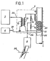
- the device shown in FIG. 1 comprises a source 2 of excitation current, a generator 4 of pulsed saturation current, connected to a winding 21, a measurement probe 6 and a recorder 8.
- the measurement circuit consists of a first winding 10 coupled to a second winding 12, and by a balanced bridge comprising two resistors 14 and 16 and two inductors 18 and 20.
- This measurement circuit has two inputs 22 and 23 connected to the generators 2 and 4 and an output 24 connected to the recorder 8.
- the windings 20 and 21 are arranged inside the tube 26 to be checked.
- the tube to be checked 26 passes around the windings 20 and 21, the winding 18 being kept away from the latter.
- the bridge is unbalanced and the defect highlighted by the recorder 8, according to a known process.
- the alternation of saturation current in the winding 21 causes a duplication 28 of the recording delivered by the recorder8.
- the width of this duplication is a function of the carburetion and its length corresponds to the length of the carbureted zone (taking into account the speed of movement of the part and the speed of unwinding of the recorder).
- FIG. 2 describes a circuit which makes it possible to deliver current slots with rounded sides, which avoids overvoltages in the measurement winding.
- the circuit shown comprises a supply circuit 30, an oscillator 32, a power stage 34, a control circuit 36, a switching member 38.
- the supply circuit 30 comprises a transformer with primary winding 40 and two secondary windings 42 and 44 connected respectively to rectifiers 46 and 48, which supply DC bias voltages.
- the oscillator 32 is conventionally constituted by two transistors 50 and 52 mounted in rocker and by an output transistor 54 driven on its base. The collector of the latter constitutes the output of the oscillator.
- the power stage 34 comprises two transistors 56 and 57, the base of the first being connected by an adjustable potentiometer 58 with, in parallel a Zener diode 60, to the collector of the transistor 54.
- the collector of the second is connected to the output terminals 62 of the circuit. Between these terminals are inserted a filter capacitor 64 and a diode 66.
- the shape of the voltage delivered is represented by the wave 65.
- the control circuit 36 includes an ammeter 68, a transistor 70 and indicator lights 72 and 74.
- the switching member 38 comprises a switch 76 with three positions: 0, slots and continuous.
- the circuit shown can deliver under 50 Ohms a rectangular voltage of period 50 ms and amplitude 12 V, the flanks of which are rounded, which prevents the appearance, in the recording, of peaks due to sudden variations in the intensity saturation current.
Landscapes
- Chemical & Material Sciences (AREA)
- Chemical Kinetics & Catalysis (AREA)
- Electrochemistry (AREA)
- Physics & Mathematics (AREA)
- Health & Medical Sciences (AREA)
- Life Sciences & Earth Sciences (AREA)
- Analytical Chemistry (AREA)
- Biochemistry (AREA)
- General Health & Medical Sciences (AREA)
- General Physics & Mathematics (AREA)
- Immunology (AREA)
- Pathology (AREA)
- Investigating Or Analyzing Materials By The Use Of Magnetic Means (AREA)
Applications Claiming Priority (2)
| Application Number | Priority Date | Filing Date | Title |
|---|---|---|---|
| FR7919331A FR2462708A1 (fr) | 1979-07-26 | 1979-07-26 | Procede et dispositif de controle non destructif par courants de foucault pour la detection de zones carburees |
| FR7919331 | 1979-07-26 |
Publications (2)
| Publication Number | Publication Date |
|---|---|
| EP0023456A1 EP0023456A1 (fr) | 1981-02-04 |
| EP0023456B1 true EP0023456B1 (fr) | 1983-09-14 |
Family
ID=9228335
Family Applications (1)
| Application Number | Title | Priority Date | Filing Date |
|---|---|---|---|
| EP19800401097 Expired EP0023456B1 (fr) | 1979-07-26 | 1980-07-23 | Procédé et dispositif de contrôle non destructif par courants de Foucault pour la détection de zônes carburées |
Country Status (3)
| Country | Link |
|---|---|
| EP (1) | EP0023456B1 (ref) |
| DE (1) | DE3064819D1 (ref) |
| FR (1) | FR2462708A1 (ref) |
Families Citing this family (4)
| Publication number | Priority date | Publication date | Assignee | Title |
|---|---|---|---|---|
| EP0204860B1 (en) * | 1985-06-13 | 1989-01-25 | Ibm Deutschland Gmbh | Methods and arrangements for characterizing magnetic coating compositions as well as improving magnetic particle dispersions |
| FR2645964B1 (fr) * | 1989-04-18 | 1991-07-26 | Siderurgie Fse Inst Rech | Procede et dispositif de controle non destructif de materiau magnetique presentant un gradient de structure dans sa partie superficielle |
| GB9205841D0 (en) * | 1992-03-18 | 1992-04-29 | Exxon Chemical Patents Inc | Hydrocarbon resins,processes for their manufacture and adhesive compositions containing such resins |
| CN101865883B (zh) * | 2010-06-21 | 2013-01-23 | 南京航空航天大学 | 脉冲涡流应力裂纹集成检测系统及方法 |
Family Cites Families (4)
| Publication number | Priority date | Publication date | Assignee | Title |
|---|---|---|---|---|
| US2258837A (en) * | 1939-05-18 | 1941-10-14 | Magnetic Analysis Corp | Electrical testing |
| GB936033A (en) * | 1960-01-18 | 1963-09-04 | Accles & Pollock Ltd | Method of, and means for detecting defects in elongated metallic objects |
| US3913009A (en) * | 1974-03-12 | 1975-10-14 | Vladimir Vasilievich Panasjuk | Method of inspecting powder-cored electrodes and device for effecting said method |
| DE2622490A1 (de) * | 1976-05-20 | 1977-12-01 | Foerster Inst Dr Friedrich | Verfahren und einrichtung zum pruefen von langgestrecktem, ferromagnetischem pruefgut auf fehler |
-
1979
- 1979-07-26 FR FR7919331A patent/FR2462708A1/fr active Granted
-
1980
- 1980-07-23 EP EP19800401097 patent/EP0023456B1/fr not_active Expired
- 1980-07-23 DE DE8080401097T patent/DE3064819D1/de not_active Expired
Also Published As
| Publication number | Publication date |
|---|---|
| EP0023456A1 (fr) | 1981-02-04 |
| FR2462708B1 (ref) | 1983-04-08 |
| FR2462708A1 (fr) | 1981-02-13 |
| DE3064819D1 (en) | 1983-10-20 |
Similar Documents
| Publication | Publication Date | Title |
|---|---|---|
| EP0194225B1 (fr) | Transformateur d'intensité pour courant continu et alternatif | |
| KR930010556A (ko) | 전자유도형 검사장치 및 검사방법 | |
| FR2528568A1 (fr) | Sonde de jauge d'epaisseur a courants de foucault | |
| GB2262346A (en) | Detecting defects in steel material | |
| EP0023456B1 (fr) | Procédé et dispositif de contrôle non destructif par courants de Foucault pour la détection de zônes carburées | |
| FR2596194A1 (fr) | Procede et appareil pour le calibrage automatique d'aimants permanents | |
| US2162710A (en) | Apparatus and method for detecting defects in metallic objects | |
| EP0736173B1 (fr) | Procede et dispositif de controle magnetique de produits metalliques | |
| CA2953295C (en) | Apparatus and method for detection of imperfections by detecting changes in flux of a magnetized body | |
| EP0492394B1 (fr) | Dispositif de contrÔle non destructif à courants de Foucault, à commutation flux additifs-flux soustractifs | |
| JP4175181B2 (ja) | 漏洩磁束探傷装置 | |
| CH386560A (fr) | Appareil pour la vérification d'un échantillon de matière conductrice par des courants de Foucault | |
| JPH05203629A (ja) | 電磁気探傷方法およびその装置 | |
| FR2601139A1 (fr) | Dispositif d'aimantation pour le controle magnetosc opique de pieces | |
| JPH09229905A (ja) | 磁気センサアレイの校正方法 | |
| FR2859022A1 (fr) | Dispositif pour mesurer l'intensite d'un courant fort parcourant un fil | |
| EP0783110B1 (fr) | Capteur de courant à large gamme de fonctionnement | |
| JPH0815229A (ja) | 高分解能渦電流探傷装置 | |
| GB1070859A (en) | Apparatus for the measurement of changes in diameter of wire or tubular metal and a method for the determination of the corrosion of such metal | |
| JPH11211698A (ja) | 磁気探傷装置の感度校正方法および装置ならびに校正 ロール | |
| FR2464525A1 (fr) | Procede et appareil d'identification de pieces ou similaires | |
| JPWO2006059497A1 (ja) | 超電導体の臨界電流密度測定方法及び装置 | |
| FR2502337A1 (fr) | Procede de controle non destructif par courants de foucault avec correction des effets d'entrefer et dispositif de mise en oeuvre | |
| Vigness et al. | Eddy Current Type Flaw Detectors for Non‐Magnetic Metals | |
| JP3223991U (ja) | 非破壊検査装置 |
Legal Events
| Date | Code | Title | Description |
|---|---|---|---|
| PUAI | Public reference made under article 153(3) epc to a published international application that has entered the european phase |
Free format text: ORIGINAL CODE: 0009012 |
|
| AK | Designated contracting states |
Designated state(s): BE DE FR GB IT NL SE |
|
| 17P | Request for examination filed |
Effective date: 19810709 |
|
| ITF | It: translation for a ep patent filed | ||
| GRAA | (expected) grant |
Free format text: ORIGINAL CODE: 0009210 |
|
| AK | Designated contracting states |
Designated state(s): BE DE FR GB IT NL SE |
|
| REF | Corresponds to: |
Ref document number: 3064819 Country of ref document: DE Date of ref document: 19831020 |
|
| PLBE | No opposition filed within time limit |
Free format text: ORIGINAL CODE: 0009261 |
|
| STAA | Information on the status of an ep patent application or granted ep patent |
Free format text: STATUS: NO OPPOSITION FILED WITHIN TIME LIMIT |
|
| 26N | No opposition filed | ||
| ITTA | It: last paid annual fee | ||
| PGFP | Annual fee paid to national office [announced via postgrant information from national office to epo] |
Ref country code: SE Payment date: 19930630 Year of fee payment: 14 |
|
| PGFP | Annual fee paid to national office [announced via postgrant information from national office to epo] |
Ref country code: DE Payment date: 19930705 Year of fee payment: 14 |
|
| PGFP | Annual fee paid to national office [announced via postgrant information from national office to epo] |
Ref country code: BE Payment date: 19930706 Year of fee payment: 14 |
|
| PGFP | Annual fee paid to national office [announced via postgrant information from national office to epo] |
Ref country code: GB Payment date: 19930719 Year of fee payment: 14 |
|
| PGFP | Annual fee paid to national office [announced via postgrant information from national office to epo] |
Ref country code: FR Payment date: 19930722 Year of fee payment: 14 |
|
| PGFP | Annual fee paid to national office [announced via postgrant information from national office to epo] |
Ref country code: NL Payment date: 19930731 Year of fee payment: 14 |
|
| PG25 | Lapsed in a contracting state [announced via postgrant information from national office to epo] |
Ref country code: GB Effective date: 19940723 |
|
| PG25 | Lapsed in a contracting state [announced via postgrant information from national office to epo] |
Ref country code: SE Effective date: 19940724 |
|
| PG25 | Lapsed in a contracting state [announced via postgrant information from national office to epo] |
Ref country code: BE Effective date: 19940731 |
|
| BERE | Be: lapsed |
Owner name: COMMISSARIAT A L'ENERGIE ATOMIQUE ETABLISSEMENT D Effective date: 19940731 |
|
| EUG | Se: european patent has lapsed |
Ref document number: 80401097.3 Effective date: 19950210 |
|
| PG25 | Lapsed in a contracting state [announced via postgrant information from national office to epo] |
Ref country code: NL Effective date: 19950201 |
|
| NLV4 | Nl: lapsed or anulled due to non-payment of the annual fee | ||
| GBPC | Gb: european patent ceased through non-payment of renewal fee |
Effective date: 19940723 |
|
| PG25 | Lapsed in a contracting state [announced via postgrant information from national office to epo] |
Ref country code: FR Effective date: 19950331 |
|
| PG25 | Lapsed in a contracting state [announced via postgrant information from national office to epo] |
Ref country code: DE Effective date: 19950401 |
|
| EUG | Se: european patent has lapsed |
Ref document number: 80401097.3 |
|
| REG | Reference to a national code |
Ref country code: FR Ref legal event code: ST |