EP0023189B1 - Perfectionnements aux dispositifs de raccord rapide pour la jonction des canalisations - Google Patents
Perfectionnements aux dispositifs de raccord rapide pour la jonction des canalisations Download PDFInfo
- Publication number
- EP0023189B1 EP0023189B1 EP80420092A EP80420092A EP0023189B1 EP 0023189 B1 EP0023189 B1 EP 0023189B1 EP 80420092 A EP80420092 A EP 80420092A EP 80420092 A EP80420092 A EP 80420092A EP 0023189 B1 EP0023189 B1 EP 0023189B1
- Authority
- EP
- European Patent Office
- Prior art keywords
- pusher
- bar
- annular depression
- female element
- notch
- Prior art date
- Legal status (The legal status is an assumption and is not a legal conclusion. Google has not performed a legal analysis and makes no representation as to the accuracy of the status listed.)
- Expired
Links
- 230000009471 action Effects 0.000 claims description 3
- 230000007246 mechanism Effects 0.000 description 4
- 238000006073 displacement reaction Methods 0.000 description 3
- 230000008878 coupling Effects 0.000 description 2
- 238000010168 coupling process Methods 0.000 description 2
- 238000005859 coupling reaction Methods 0.000 description 2
- 238000010276 construction Methods 0.000 description 1
- 238000010494 dissociation reaction Methods 0.000 description 1
- 230000005593 dissociations Effects 0.000 description 1
- 238000003754 machining Methods 0.000 description 1
- 230000014759 maintenance of location Effects 0.000 description 1
Images


Classifications
-
- F—MECHANICAL ENGINEERING; LIGHTING; HEATING; WEAPONS; BLASTING
- F16—ENGINEERING ELEMENTS AND UNITS; GENERAL MEASURES FOR PRODUCING AND MAINTAINING EFFECTIVE FUNCTIONING OF MACHINES OR INSTALLATIONS; THERMAL INSULATION IN GENERAL
- F16L—PIPES; JOINTS OR FITTINGS FOR PIPES; SUPPORTS FOR PIPES, CABLES OR PROTECTIVE TUBING; MEANS FOR THERMAL INSULATION IN GENERAL
- F16L37/00—Couplings of the quick-acting type
- F16L37/22—Couplings of the quick-acting type in which the connection is maintained by means of balls, rollers or helical springs under radial pressure between the parts
-
- F—MECHANICAL ENGINEERING; LIGHTING; HEATING; WEAPONS; BLASTING
- F16—ENGINEERING ELEMENTS AND UNITS; GENERAL MEASURES FOR PRODUCING AND MAINTAINING EFFECTIVE FUNCTIONING OF MACHINES OR INSTALLATIONS; THERMAL INSULATION IN GENERAL
- F16L—PIPES; JOINTS OR FITTINGS FOR PIPES; SUPPORTS FOR PIPES, CABLES OR PROTECTIVE TUBING; MEANS FOR THERMAL INSULATION IN GENERAL
- F16L37/00—Couplings of the quick-acting type
- F16L37/08—Couplings of the quick-acting type in which the connection between abutting or axially overlapping ends is maintained by locking members
- F16L37/084—Couplings of the quick-acting type in which the connection between abutting or axially overlapping ends is maintained by locking members combined with automatic locking
- F16L37/0841—Couplings of the quick-acting type in which the connection between abutting or axially overlapping ends is maintained by locking members combined with automatic locking by means of a transversally slidable locking member surrounding the tube
Definitions
- the present invention relates to quick couplings intended to ensure the junction of two pipes and consisting of a male element and a female element suitable for fitting tightly one inside the other and to be immobilized axially by a locking mechanism, causing if necessary the automatic opening of a valve charged with closing.
- the locking mechanism comprises at least one cylindrical bar oriented transversely relative to the axis of the body of the female element and mounted to slide inside oblique notches made in the aforementioned body, so as to engage elastically, under the effect of a return spring suitably arranged, in an annular depression provided on the fitting end of the male element.
- ZAJAC U.S.A. Patent No. 2,913,263
- the locking for the dissociation of the two elements is effected by means of an external sleeve mounted with axial sliding on the external front wall of the body of the female element.
- This sleeve is arranged in such a way that its axial displacement towards the rear releases the bar, thereby allowing the male element to be withdrawn under the effect of a simple axial traction exerted on said element.
- the axial sliding release sleeve is particularly vulnerable on the periphery of the body of the female element. It is thus subjected to significant deformations which relatively frequently cause more or less serious damage. In addition, its displacement in the axial direction risks determining its untimely operation, in particular when during a longitudinal movement of the pipes on the ground, said sleeve abuts against any fixed part.
- the improvements which are the subject of the present invention aim to remedy the above-mentioned drawbacks and to allow the realization of a quick connector of the above-mentioned kind which is capable of responding particularly well to the various desiderata of the practice, in particular in regarding the reliability of the unlocking system.
- the quick connector according to the invention is of the known type comprising a male element provided with a tip hollowed out of an annular depression and a female element having at least one oblique notch situated opposite said annular depression, the locking of the element male in the female element being provided by at least one movable cylindrical bar inside said oblique notch and urged by elastic means oriented in a substantially axial direction and which tend, by pushing said bar into the aforementioned notch. to engage it in annular depression. while there is provided an unlocking member to act on the bar to release the tip.
- such a hollow pusher is capable of being embedded in the body of the female element, thus being sheltered from untimely deformations or stresses, while being able to be very easily maneuvered by the operator. with a view to dissociating the two elements of the device.
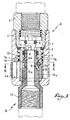
- the body of the female element A of the quick coupling shown in fig. 1 consists of the assembly of two tubular parts 1 and 2, screwed with the interposition of a seal 3.
- Part 2 intended to be fixed to the end of one of the two pipes to be connected.
- part 1 is fixed a socket 7, the opening of which is fitted with an O-ring 8: this socket is cut out by a notch 7a oriented obliquely from the outside to the inside from the rear part of the body 1-2 , which notch 7a forms a housing for a cylindrical locking bar 9.
- a washer 10, biased by a spring 11, tends to push the bar 9 forward.
- the bar 9 is capable, under the effect of the spring 11, of engaging in a depression 12a provided behind a flange 12b with a frustoconical profile formed on the end piece 12c of the body 12 of the male element B.
- This body 12 is designed to be fixed to the end of the second pipe.
- the end piece 12c is dimensioned to fit into the socket 7 and push the loaded valve 4 back into the open position, the seal 8 ensuring the connection is sealed.
- the unlocking member is constituted by a hollow pusher 13 movable in a transverse notch 1a a of the part 1 of the body 1-2.
- This pusher 13 has a closed profile for overlapping the sleeve 7 which cooperates in its guidance; at its lower part, its rearward-facing edge is cut out by a ramp 13a (fig. 3) with a square profile, which ramp forms a stop for the bar 9 which under the effect of its spring 11 tends to push back towards outside said pusher 13.
- the outer wall of the pusher 13 is located practically at the level of the outer wall of the part 1.
- this pusher 13 does not in any way interfere with the operation of the locking mechanism, the bar 9 engaging in the depression 12a of the body of the male element.
- a pressure exerted in the direction indicated by the arrow F of Figure 3 has the effect of driving the pusher inside the body of the female element.
- the ramp 13a bearing against the bar 9 then moves the latter which comes to affect a radial position tette that frees the flange 12b, the tip 12c of the male element B can thus be released from the female element A.
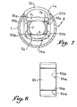
- FIG. 5 and 6 illustrate an embodiment of the invention in which the locking mechanism comprises two cylindrical bars 9 oriented parallel to one another.
- the central sleeve 7 has two notches or oblique housings 7a to receive these two bars which are biased by the same spring 11 associated with the same washer 10, while the pusher, here referenced 23, is cut from two ramps 23a.
- One of these, namely that which is situated on the side opposite to the actuating surface of the pusher, is identical to the ramp 13a of FIG. 1 to 4, while the other is formed (FIG. 6) by two opposite parts obtained by machining the rear edge of said pusher. Locking and unlocking operation is quite similar to that described above.
- the pusher referenced 33 comprises, in addition to the actuating ramps 33a, facets 33b which close said ramps laterally and which form stops limiting the axial displacement of the aforementioned bars.
Landscapes
- Engineering & Computer Science (AREA)
- General Engineering & Computer Science (AREA)
- Mechanical Engineering (AREA)
- Quick-Acting Or Multi-Walled Pipe Joints (AREA)
Applications Claiming Priority (2)
| Application Number | Priority Date | Filing Date | Title |
|---|---|---|---|
| FR7919383 | 1979-07-23 | ||
| FR7919383A FR2461876A1 (fr) | 1979-07-23 | 1979-07-23 | Perfectionnements aux dispositifs de raccord rapide pour la jonction des canalisations |
Publications (2)
| Publication Number | Publication Date |
|---|---|
| EP0023189A1 EP0023189A1 (fr) | 1981-01-28 |
| EP0023189B1 true EP0023189B1 (fr) | 1984-01-18 |
Family
ID=9228353
Family Applications (1)
| Application Number | Title | Priority Date | Filing Date |
|---|---|---|---|
| EP80420092A Expired EP0023189B1 (fr) | 1979-07-23 | 1980-07-21 | Perfectionnements aux dispositifs de raccord rapide pour la jonction des canalisations |
Country Status (4)
| Country | Link |
|---|---|
| US (1) | US4311328A (show.php) |
| EP (1) | EP0023189B1 (show.php) |
| DE (1) | DE3066170D1 (show.php) |
| FR (1) | FR2461876A1 (show.php) |
Families Citing this family (31)
| Publication number | Priority date | Publication date | Assignee | Title |
|---|---|---|---|---|
| US4603886A (en) * | 1984-03-26 | 1986-08-05 | Vetco Offshore, Inc. | Snap type pipe connector |
| IT220672Z2 (it) * | 1990-11-13 | 1993-10-11 | Itw Fastex Italia Spa | Dispositivo di collegamento a scatto, a tenuta di fluido, per tubazioni |
| US5447343A (en) * | 1993-09-28 | 1995-09-05 | American Sterilizer Company | Rigid endoscope connector |
| US5485982A (en) * | 1994-09-16 | 1996-01-23 | Bundy Corporation | Quick connector with tube activated check valve |
| US5445358A (en) * | 1994-12-16 | 1995-08-29 | Parker-Hannifin Corporation | Exhaust type quick action coupler |
| US5857481A (en) * | 1996-04-17 | 1999-01-12 | Zimmerman; Lewis | Tire inflation system and process |
| EP0803676B1 (de) * | 1996-04-23 | 2001-09-26 | Christian Heilmann | Schnellkupplung für die Verbindung von Schlauch- und Rohrleitungen |
| US6557824B1 (en) * | 2000-10-20 | 2003-05-06 | Eaton Aeroquip | Releasable coupling assembly |
| FR2835585B1 (fr) * | 2002-02-04 | 2004-03-05 | Staubli Sa Ets | Raccord rapide pour la jonction amovible de deux canalisations |
| US6769720B2 (en) * | 2002-08-27 | 2004-08-03 | Eaton Corporation | Coupling assembly with profiled ramp |
| FR2847330A1 (fr) * | 2002-11-19 | 2004-05-21 | Staubli Sa Ets | Raccord rapide pour la jonction amovible de deux canalisations |
| FR2862369B1 (fr) * | 2003-11-13 | 2008-01-04 | Staubli Sa Ets | Element femelle de raccord et raccord rapide incorporant un tel element |
| US7077382B2 (en) | 2004-07-13 | 2006-07-18 | Itt Manufacturing Enterprises, Inc. | Water supply shut off valve with quick connect having flow regulation |
| US9052047B2 (en) * | 2010-06-03 | 2015-06-09 | Keith Covert | Quick connect coupler for glass container molding machine |
| WO2012051481A1 (en) | 2010-10-15 | 2012-04-19 | Swagelok Company | Push to connect conduit fitting with ferrule |
| CN103518093B (zh) * | 2011-03-18 | 2016-10-05 | A·雷蒙德公司 | 快速接头 |
| FR2985554B1 (fr) * | 2012-01-10 | 2014-02-14 | Wichard | Dispositif de connexion mecanique pour relier une charge a un support |
| TWM441579U (en) * | 2012-05-11 | 2012-11-21 | Jin Dai Auto Supplies Co Ltd | Two-way inflation apparatus |
| US9175795B2 (en) | 2012-05-29 | 2015-11-03 | Parker-Hannifin Corporation | Coupling with locking bars |
| US10247520B2 (en) * | 2013-05-13 | 2019-04-02 | Joseph A. Manly | Tactical accessory attachment system |
| CN109555926B (zh) | 2013-10-24 | 2021-07-02 | 世伟洛克公司 | 单动推动即可连接管道接头 |
| FR3014166B1 (fr) * | 2013-12-02 | 2016-01-15 | Staubli Sa Ets | Raccord rapide pour la jonction amovible de deux canalisations |
| US11187360B2 (en) * | 2014-10-23 | 2021-11-30 | Idex Health & Science Llc | Fluidic connector assembly for quick connect/disconnect |
| US10458582B2 (en) | 2015-04-23 | 2019-10-29 | Swagelok Company | Single action push to connect conduit fitting with colleting |
| ES2755400T3 (es) | 2015-04-23 | 2020-04-22 | Swagelok Co | Conjunto de conector de empuje para conexión para un conducto |
| CN108930857B (zh) * | 2017-05-25 | 2024-06-25 | 珠海三德艺电子有限公司 | 轮胎充气快速夹头 |
| US10712014B2 (en) * | 2018-02-21 | 2020-07-14 | Earthcore Industries, Llc | Modular linear fireplace gas burner system |
| FR3090797B1 (fr) * | 2018-12-21 | 2021-01-22 | Staubli Sa Ets | Elément femelle de raccord et raccord fluidique comprenant un élément mâle de raccord ainsi que ledit élément femelle de raccord |
| EP3948042B1 (en) | 2019-04-01 | 2025-01-08 | Swagelok Company | Push to connect conduit fitting assemblies and arrangements |
| FR3084133B1 (fr) * | 2019-04-02 | 2020-11-20 | Parker Hannifin Emea Sarl | Dispositif de raccordement avec une position intermédiaire de déverrouillage |
| CN111855021B (zh) * | 2020-08-25 | 2025-04-15 | 深圳市凌晨知识产权运营有限公司 | 一种高智能动态人脸识别测温一体机 |
Family Cites Families (9)
| Publication number | Priority date | Publication date | Assignee | Title |
|---|---|---|---|---|
| FR414280A (fr) | 1909-03-11 | 1910-08-30 | John Luther Jackson | Jante amovible à démontage rapide du pneumatique |
| GB473221A (en) * | 1936-09-22 | 1937-10-08 | Ivan Leclere Eastman | An improved disconnectible coupler for hose and the like |
| US2626974A (en) * | 1949-09-16 | 1953-01-27 | Pyle National Co | Explosion proof plug and socket |
| US2913263A (en) * | 1957-07-05 | 1959-11-17 | Zalo Mfg Company | Pin detent pipe or tube coupling with manipulator |
| US3155402A (en) * | 1960-04-11 | 1964-11-03 | Richard T Cornelius | Manual disconnect coupling with pivoted lever having detent engaging facing cams |
| FR1384065A (fr) * | 1963-11-12 | 1965-01-04 | Staubli Freres & Cie | Dispositif de raccord rapide pour canalisations et analogues |
| FR1403103A (fr) * | 1964-05-05 | 1965-06-18 | Staubli Freres & Cie | Dispositif de raccord rapide pour canalisations et analogues |
| FR1487323A (fr) * | 1966-01-04 | 1967-07-07 | Staubli Freres & Cie | Dispositif de raccord rapide pour la jonction de canalisations et analogues |
| US3503637A (en) * | 1967-06-15 | 1970-03-31 | Sosaburo Maeshiba | Pipe coupling with spring biased detents |
-
1979
- 1979-07-23 FR FR7919383A patent/FR2461876A1/fr active Granted
-
1980
- 1980-07-21 DE DE8080420092T patent/DE3066170D1/de not_active Expired
- 1980-07-21 EP EP80420092A patent/EP0023189B1/fr not_active Expired
- 1980-07-22 US US06/171,058 patent/US4311328A/en not_active Expired - Lifetime
Also Published As
| Publication number | Publication date |
|---|---|
| EP0023189A1 (fr) | 1981-01-28 |
| DE3066170D1 (en) | 1984-02-23 |
| US4311328A (en) | 1982-01-19 |
| FR2461876B1 (show.php) | 1983-06-03 |
| FR2461876A1 (fr) | 1981-02-06 |
Similar Documents
| Publication | Publication Date | Title |
|---|---|---|
| EP0023189B1 (fr) | Perfectionnements aux dispositifs de raccord rapide pour la jonction des canalisations | |
| EP0722063B1 (fr) | Raccord rapide de sécurité pour la jonction amovible de canalisations | |
| EP2439440B1 (fr) | Dispositif de raccord avec verrouillage par griffes filetées et raccord comprenant un tel dispositif | |
| EP1135643B1 (fr) | Coupleur a billes | |
| FR3059756B1 (fr) | Dispositif pour le raccordement d'une conduite de fluide et un raccord male, et ensemble comprenant un tel dispositif et ledit raccord male associe | |
| FR2847329A1 (fr) | Raccord rapide pour la jonction amovible de deux canalisations | |
| EP0488844A1 (fr) | Dispositif de raccord, notamment pour l'assemblage d'une durite à un échangeur de chaleur de véhicule automobile | |
| EP0670449A1 (fr) | Dispositif de raccordement rapide et étanche pour conduites tubulaires | |
| FR2772458A1 (fr) | Dispositif de raccordement rapide d'un tube a un element rigide a bague anti-extraction et temoin d'integrite | |
| EP0077743A1 (fr) | Perfectionnements aux raccords rapides pour la jonction amovible des canalisations | |
| CA3135534C (fr) | Dispositif de raccordement avec une position intermediaire de deverrouillage | |
| EP0877891B1 (fr) | Raccord rapide etanche | |
| EP1422461A1 (fr) | Raccord rapide pour la jonction amovible de deux canalisations | |
| FR3046209A1 (fr) | Element femelle de raccord rapide et raccord rapide comprenant un tel element femelle | |
| FR2630524A1 (fr) | Coupleur a clapets a douille exterieure mobile | |
| CH472623A (fr) | Dispositif de raccordement de canalisations | |
| FR2855239A1 (fr) | Raccord rapide pour conduites de fluide hydraulique | |
| FR2545908A1 (fr) | Raccord rapide de securite pour la jonction amovible des canalisations | |
| EP0811797B1 (fr) | Raccord rapide de sécurité pour la jonction amovible des canalisations | |
| EP1020677A1 (fr) | Ensemble de connexion d'une extrémité de conduite à un élément | |
| FR1487323A (fr) | Dispositif de raccord rapide pour la jonction de canalisations et analogues | |
| FR2761974A1 (fr) | Clapet anti-retour pour une canalisation de remplissage de reservoir de carburant de vehicule automobile et de canalisation | |
| EP0085010B1 (fr) | Coupleur auto-obturateur, notamment pour fluide ou réfrigérant | |
| FR2481401A1 (fr) | Perfectionnements aux raccords-vannes de securite | |
| FR2510227A1 (fr) | Perfectionnements aux raccords tournants pour tuyauteries |
Legal Events
| Date | Code | Title | Description |
|---|---|---|---|
| PUAI | Public reference made under article 153(3) epc to a published international application that has entered the european phase |
Free format text: ORIGINAL CODE: 0009012 |
|
| AK | Designated contracting states |
Designated state(s): CH DE GB IT LI SE |
|
| 17P | Request for examination filed |
Effective date: 19810418 |
|
| RAP1 | Party data changed (applicant data changed or rights of an application transferred) |
Owner name: S.A. DES ETABLISSEMENTS STAUBLI (FRANCE) |
|
| ITF | It: translation for a ep patent filed | ||
| GRAA | (expected) grant |
Free format text: ORIGINAL CODE: 0009210 |
|
| AK | Designated contracting states |
Designated state(s): CH DE GB IT LI SE |
|
| REF | Corresponds to: |
Ref document number: 3066170 Country of ref document: DE Date of ref document: 19840223 |
|
| PLBE | No opposition filed within time limit |
Free format text: ORIGINAL CODE: 0009261 |
|
| STAA | Information on the status of an ep patent application or granted ep patent |
Free format text: STATUS: NO OPPOSITION FILED WITHIN TIME LIMIT |
|
| 26N | No opposition filed | ||
| ITTA | It: last paid annual fee | ||
| PGFP | Annual fee paid to national office [announced via postgrant information from national office to epo] |
Ref country code: GB Payment date: 19920713 Year of fee payment: 13 |
|
| PGFP | Annual fee paid to national office [announced via postgrant information from national office to epo] |
Ref country code: CH Payment date: 19920716 Year of fee payment: 13 |
|
| PGFP | Annual fee paid to national office [announced via postgrant information from national office to epo] |
Ref country code: SE Payment date: 19920720 Year of fee payment: 13 |
|
| PGFP | Annual fee paid to national office [announced via postgrant information from national office to epo] |
Ref country code: DE Payment date: 19920828 Year of fee payment: 13 |
|
| PG25 | Lapsed in a contracting state [announced via postgrant information from national office to epo] |
Ref country code: GB Effective date: 19930721 |
|
| PG25 | Lapsed in a contracting state [announced via postgrant information from national office to epo] |
Ref country code: SE Effective date: 19930722 |
|
| PG25 | Lapsed in a contracting state [announced via postgrant information from national office to epo] |
Ref country code: LI Effective date: 19930731 Ref country code: CH Effective date: 19930731 |
|
| GBPC | Gb: european patent ceased through non-payment of renewal fee |
Effective date: 19930721 |
|
| REG | Reference to a national code |
Ref country code: CH Ref legal event code: PL |
|
| PG25 | Lapsed in a contracting state [announced via postgrant information from national office to epo] |
Ref country code: DE Effective date: 19940401 |
|
| EUG | Se: european patent has lapsed |
Ref document number: 80420092.1 Effective date: 19940210 |