EP0022849B1 - Method and apparatus for manufacturing a plastics solar panel structure - Google Patents
Method and apparatus for manufacturing a plastics solar panel structure Download PDFInfo
- Publication number
- EP0022849B1 EP0022849B1 EP80900333A EP80900333A EP0022849B1 EP 0022849 B1 EP0022849 B1 EP 0022849B1 EP 80900333 A EP80900333 A EP 80900333A EP 80900333 A EP80900333 A EP 80900333A EP 0022849 B1 EP0022849 B1 EP 0022849B1
- Authority
- EP
- European Patent Office
- Prior art keywords
- thin wall
- wall sections
- fluid
- exterior
- panel structure
- Prior art date
- Legal status (The legal status is an assumption and is not a legal conclusion. Google has not performed a legal analysis and makes no representation as to the accuracy of the status listed.)
- Expired
Links
- 239000004033 plastic Substances 0.000 title claims abstract description 90
- 229920003023 plastic Polymers 0.000 title claims abstract description 90
- 238000000034 method Methods 0.000 title claims abstract description 51
- 238000004519 manufacturing process Methods 0.000 title claims description 8
- 239000012530 fluid Substances 0.000 claims abstract description 126
- 239000000463 material Substances 0.000 claims abstract description 105
- 238000001125 extrusion Methods 0.000 claims abstract description 76
- 238000000576 coating method Methods 0.000 claims abstract description 67
- 239000011248 coating agent Substances 0.000 claims abstract description 47
- 239000007788 liquid Substances 0.000 claims abstract description 30
- 230000005855 radiation Effects 0.000 claims abstract description 15
- 230000002708 enhancing effect Effects 0.000 claims abstract description 5
- 239000000203 mixture Substances 0.000 claims description 43
- IJGRMHOSHXDMSA-UHFFFAOYSA-N Atomic nitrogen Chemical compound N#N IJGRMHOSHXDMSA-UHFFFAOYSA-N 0.000 claims description 26
- 239000004816 latex Substances 0.000 claims description 23
- 229920000126 latex Polymers 0.000 claims description 23
- 229920000515 polycarbonate Polymers 0.000 claims description 23
- 239000004417 polycarbonate Substances 0.000 claims description 23
- 239000004615 ingredient Substances 0.000 claims description 19
- 239000007789 gas Substances 0.000 claims description 16
- XLYOFNOQVPJJNP-UHFFFAOYSA-N water Substances O XLYOFNOQVPJJNP-UHFFFAOYSA-N 0.000 claims description 15
- 239000007787 solid Substances 0.000 claims description 14
- 229910052757 nitrogen Inorganic materials 0.000 claims description 13
- IJOOHPMOJXWVHK-UHFFFAOYSA-N chlorotrimethylsilane Chemical compound C[Si](C)(C)Cl IJOOHPMOJXWVHK-UHFFFAOYSA-N 0.000 claims description 12
- 230000007797 corrosion Effects 0.000 claims description 11
- 238000005260 corrosion Methods 0.000 claims description 11
- 239000002103 nanocoating Substances 0.000 claims description 11
- 239000011261 inert gas Substances 0.000 claims description 10
- 239000002966 varnish Substances 0.000 claims description 8
- 230000009467 reduction Effects 0.000 claims description 7
- 239000002904 solvent Substances 0.000 claims description 7
- BFKJFAAPBSQJPD-UHFFFAOYSA-N tetrafluoroethene Chemical group FC(F)=C(F)F BFKJFAAPBSQJPD-UHFFFAOYSA-N 0.000 claims description 7
- 239000006104 solid solution Substances 0.000 claims description 6
- 239000005051 trimethylchlorosilane Substances 0.000 claims description 6
- 239000002033 PVDF binder Substances 0.000 claims description 5
- 239000005083 Zinc sulfide Substances 0.000 claims description 5
- 230000015572 biosynthetic process Effects 0.000 claims description 5
- 239000012809 cooling fluid Substances 0.000 claims description 5
- 230000006866 deterioration Effects 0.000 claims description 5
- 230000009969 flowable effect Effects 0.000 claims description 5
- 229920002981 polyvinylidene fluoride Polymers 0.000 claims description 5
- 150000003839 salts Chemical class 0.000 claims description 5
- 229910052984 zinc sulfide Inorganic materials 0.000 claims description 5
- DRDVZXDWVBGGMH-UHFFFAOYSA-N zinc;sulfide Chemical compound [S-2].[Zn+2] DRDVZXDWVBGGMH-UHFFFAOYSA-N 0.000 claims description 5
- 239000004480 active ingredient Substances 0.000 claims description 4
- 230000001965 increasing effect Effects 0.000 claims description 4
- 238000005507 spraying Methods 0.000 claims description 4
- JHPBZFOKBAGZBL-UHFFFAOYSA-N (3-hydroxy-2,2,4-trimethylpentyl) 2-methylprop-2-enoate Chemical compound CC(C)C(O)C(C)(C)COC(=O)C(C)=C JHPBZFOKBAGZBL-UHFFFAOYSA-N 0.000 claims description 3
- QYKABQMBXCBINA-UHFFFAOYSA-N 4-(oxan-2-yloxy)benzaldehyde Chemical compound C1=CC(C=O)=CC=C1OC1OCCCC1 QYKABQMBXCBINA-UHFFFAOYSA-N 0.000 claims description 3
- 125000003178 carboxy group Chemical group [H]OC(*)=O 0.000 claims description 3
- OMZSGWSJDCOLKM-UHFFFAOYSA-N copper(II) sulfide Chemical compound [S-2].[Cu+2] OMZSGWSJDCOLKM-UHFFFAOYSA-N 0.000 claims description 3
- 230000004927 fusion Effects 0.000 claims description 3
- 239000000178 monomer Substances 0.000 claims description 3
- 229920002492 poly(sulfone) Polymers 0.000 claims description 3
- UIUXUFNYAYAMOE-UHFFFAOYSA-N methylsilane Chemical compound [SiH3]C UIUXUFNYAYAMOE-UHFFFAOYSA-N 0.000 claims description 2
- 150000001282 organosilanes Chemical class 0.000 claims description 2
- 229920000642 polymer Polymers 0.000 claims description 2
- 238000002329 infrared spectrum Methods 0.000 claims 3
- 230000000717 retained effect Effects 0.000 claims 2
- 238000001429 visible spectrum Methods 0.000 claims 2
- 239000008199 coating composition Substances 0.000 claims 1
- 239000007921 spray Substances 0.000 abstract description 10
- 238000005096 rolling process Methods 0.000 abstract description 2
- 239000000376 reactant Substances 0.000 abstract 1
- 239000000654 additive Substances 0.000 description 13
- 230000000996 additive effect Effects 0.000 description 9
- 238000010438 heat treatment Methods 0.000 description 8
- 239000000853 adhesive Substances 0.000 description 7
- 230000001070 adhesive effect Effects 0.000 description 7
- -1 vapor Substances 0.000 description 7
- XKRFYHLGVUSROY-UHFFFAOYSA-N Argon Chemical compound [Ar] XKRFYHLGVUSROY-UHFFFAOYSA-N 0.000 description 6
- 238000006243 chemical reaction Methods 0.000 description 6
- 238000005553 drilling Methods 0.000 description 6
- 239000000126 substance Substances 0.000 description 6
- 230000000712 assembly Effects 0.000 description 5
- 238000000429 assembly Methods 0.000 description 5
- 238000001816 cooling Methods 0.000 description 5
- 238000005520 cutting process Methods 0.000 description 5
- 230000000694 effects Effects 0.000 description 5
- 239000002245 particle Substances 0.000 description 5
- 229920001169 thermoplastic Polymers 0.000 description 5
- 229920001187 thermosetting polymer Polymers 0.000 description 5
- 239000004416 thermosoftening plastic Substances 0.000 description 5
- OKTJSMMVPCPJKN-UHFFFAOYSA-N Carbon Chemical compound [C] OKTJSMMVPCPJKN-UHFFFAOYSA-N 0.000 description 4
- CURLTUGMZLYLDI-UHFFFAOYSA-N Carbon dioxide Chemical compound O=C=O CURLTUGMZLYLDI-UHFFFAOYSA-N 0.000 description 4
- 229920001328 Polyvinylidene chloride Polymers 0.000 description 4
- 238000005266 casting Methods 0.000 description 4
- UUAGAQFQZIEFAH-UHFFFAOYSA-N chlorotrifluoroethylene Chemical group FC(F)=C(F)Cl UUAGAQFQZIEFAH-UHFFFAOYSA-N 0.000 description 4
- 239000000835 fiber Substances 0.000 description 4
- 239000001307 helium Substances 0.000 description 4
- 229910052734 helium Inorganic materials 0.000 description 4
- SWQJXJOGLNCZEY-UHFFFAOYSA-N helium atom Chemical compound [He] SWQJXJOGLNCZEY-UHFFFAOYSA-N 0.000 description 4
- 239000008188 pellet Substances 0.000 description 4
- 239000005033 polyvinylidene chloride Substances 0.000 description 4
- 239000011347 resin Substances 0.000 description 4
- 229920005989 resin Polymers 0.000 description 4
- HBMJWWWQQXIZIP-UHFFFAOYSA-N silicon carbide Chemical compound [Si+]#[C-] HBMJWWWQQXIZIP-UHFFFAOYSA-N 0.000 description 4
- 229910010271 silicon carbide Inorganic materials 0.000 description 4
- 229920001897 terpolymer Polymers 0.000 description 4
- NNWNNQTUZYVQRK-UHFFFAOYSA-N 5-bromo-1h-pyrrolo[2,3-c]pyridine-2-carboxylic acid Chemical compound BrC1=NC=C2NC(C(=O)O)=CC2=C1 NNWNNQTUZYVQRK-UHFFFAOYSA-N 0.000 description 3
- 229920002574 CR-39 Polymers 0.000 description 3
- 239000004593 Epoxy Substances 0.000 description 3
- LYCAIKOWRPUZTN-UHFFFAOYSA-N Ethylene glycol Chemical compound OCCO LYCAIKOWRPUZTN-UHFFFAOYSA-N 0.000 description 3
- OKKJLVBELUTLKV-UHFFFAOYSA-N Methanol Chemical compound OC OKKJLVBELUTLKV-UHFFFAOYSA-N 0.000 description 3
- 229910052786 argon Inorganic materials 0.000 description 3
- 229910052799 carbon Inorganic materials 0.000 description 3
- 239000000969 carrier Substances 0.000 description 3
- 238000004891 communication Methods 0.000 description 3
- 238000010276 construction Methods 0.000 description 3
- LIKFHECYJZWXFJ-UHFFFAOYSA-N dimethyldichlorosilane Chemical compound C[Si](C)(Cl)Cl LIKFHECYJZWXFJ-UHFFFAOYSA-N 0.000 description 3
- 239000007850 fluorescent dye Substances 0.000 description 3
- 230000007246 mechanism Effects 0.000 description 3
- 238000002844 melting Methods 0.000 description 3
- 230000008018 melting Effects 0.000 description 3
- 230000003287 optical effect Effects 0.000 description 3
- 229920003229 poly(methyl methacrylate) Polymers 0.000 description 3
- 239000004926 polymethyl methacrylate Substances 0.000 description 3
- 229920001296 polysiloxane Polymers 0.000 description 3
- 229920002545 silicone oil Polymers 0.000 description 3
- 238000009718 spray deposition Methods 0.000 description 3
- 239000010935 stainless steel Substances 0.000 description 3
- 229910001220 stainless steel Inorganic materials 0.000 description 3
- 239000000725 suspension Substances 0.000 description 3
- 238000012546 transfer Methods 0.000 description 3
- XLLIQLLCWZCATF-UHFFFAOYSA-N 2-methoxyethyl acetate Chemical compound COCCOC(C)=O XLLIQLLCWZCATF-UHFFFAOYSA-N 0.000 description 2
- CSCPPACGZOOCGX-UHFFFAOYSA-N Acetone Chemical compound CC(C)=O CSCPPACGZOOCGX-UHFFFAOYSA-N 0.000 description 2
- 239000004641 Diallyl-phthalate Substances 0.000 description 2
- LFQSCWFLJHTTHZ-UHFFFAOYSA-N Ethanol Chemical compound CCO LFQSCWFLJHTTHZ-UHFFFAOYSA-N 0.000 description 2
- KFZMGEQAYNKOFK-UHFFFAOYSA-N Isopropanol Chemical compound CC(C)O KFZMGEQAYNKOFK-UHFFFAOYSA-N 0.000 description 2
- 229920001944 Plastisol Polymers 0.000 description 2
- 239000004743 Polypropylene Substances 0.000 description 2
- XUIMIQQOPSSXEZ-UHFFFAOYSA-N Silicon Chemical compound [Si] XUIMIQQOPSSXEZ-UHFFFAOYSA-N 0.000 description 2
- XLOMVQKBTHCTTD-UHFFFAOYSA-N Zinc monoxide Chemical compound [Zn]=O XLOMVQKBTHCTTD-UHFFFAOYSA-N 0.000 description 2
- NIXOWILDQLNWCW-UHFFFAOYSA-N acrylic acid group Chemical group C(C=C)(=O)O NIXOWILDQLNWCW-UHFFFAOYSA-N 0.000 description 2
- 150000001298 alcohols Chemical class 0.000 description 2
- QUDWYFHPNIMBFC-UHFFFAOYSA-N bis(prop-2-enyl) benzene-1,2-dicarboxylate Chemical compound C=CCOC(=O)C1=CC=CC=C1C(=O)OCC=C QUDWYFHPNIMBFC-UHFFFAOYSA-N 0.000 description 2
- 239000001569 carbon dioxide Substances 0.000 description 2
- 229910002092 carbon dioxide Inorganic materials 0.000 description 2
- UBAZGMLMVVQSCD-UHFFFAOYSA-N carbon dioxide;molecular oxygen Chemical compound O=O.O=C=O UBAZGMLMVVQSCD-UHFFFAOYSA-N 0.000 description 2
- 229910001567 cementite Inorganic materials 0.000 description 2
- 230000008859 change Effects 0.000 description 2
- DCFKHNIGBAHNSS-UHFFFAOYSA-N chloro(triethyl)silane Chemical compound CC[Si](Cl)(CC)CC DCFKHNIGBAHNSS-UHFFFAOYSA-N 0.000 description 2
- 239000002826 coolant Substances 0.000 description 2
- 229920001577 copolymer Polymers 0.000 description 2
- 238000009826 distribution Methods 0.000 description 2
- 239000000975 dye Substances 0.000 description 2
- 239000008246 gaseous mixture Substances 0.000 description 2
- HCDGVLDPFQMKDK-UHFFFAOYSA-N hexafluoropropylene Chemical group FC(F)=C(F)C(F)(F)F HCDGVLDPFQMKDK-UHFFFAOYSA-N 0.000 description 2
- WGCNASOHLSPBMP-UHFFFAOYSA-N hydroxyacetaldehyde Natural products OCC=O WGCNASOHLSPBMP-UHFFFAOYSA-N 0.000 description 2
- 238000009434 installation Methods 0.000 description 2
- 239000005055 methyl trichlorosilane Substances 0.000 description 2
- JLUFWMXJHAVVNN-UHFFFAOYSA-N methyltrichlorosilane Chemical compound C[Si](Cl)(Cl)Cl JLUFWMXJHAVVNN-UHFFFAOYSA-N 0.000 description 2
- 230000004048 modification Effects 0.000 description 2
- 238000012986 modification Methods 0.000 description 2
- 230000002093 peripheral effect Effects 0.000 description 2
- 239000004999 plastisol Substances 0.000 description 2
- 229920001155 polypropylene Polymers 0.000 description 2
- 230000008569 process Effects 0.000 description 2
- 238000011084 recovery Methods 0.000 description 2
- 229910052710 silicon Inorganic materials 0.000 description 2
- 239000010703 silicon Substances 0.000 description 2
- 239000000243 solution Substances 0.000 description 2
- GETTZEONDQJALK-UHFFFAOYSA-N (trifluoromethyl)benzene Chemical group FC(F)(F)C1=CC=CC=C1 GETTZEONDQJALK-UHFFFAOYSA-N 0.000 description 1
- QIGBRXMKCJKVMJ-UHFFFAOYSA-N 1,4-Benzenediol Natural products OC1=CC=C(O)C=C1 QIGBRXMKCJKVMJ-UHFFFAOYSA-N 0.000 description 1
- JLZIIHMTTRXXIN-UHFFFAOYSA-N 2-(2-hydroxy-4-methoxybenzoyl)benzoic acid Chemical compound OC1=CC(OC)=CC=C1C(=O)C1=CC=CC=C1C(O)=O JLZIIHMTTRXXIN-UHFFFAOYSA-N 0.000 description 1
- AFABGHUZZDYHJO-UHFFFAOYSA-N 2-Methylpentane Chemical compound CCCC(C)C AFABGHUZZDYHJO-UHFFFAOYSA-N 0.000 description 1
- VXEGSRKPIUDPQT-UHFFFAOYSA-N 4-[4-(4-methoxyphenyl)piperazin-1-yl]aniline Chemical compound C1=CC(OC)=CC=C1N1CCN(C=2C=CC(N)=CC=2)CC1 VXEGSRKPIUDPQT-UHFFFAOYSA-N 0.000 description 1
- 239000004925 Acrylic resin Substances 0.000 description 1
- 229920000178 Acrylic resin Polymers 0.000 description 1
- 229930185605 Bisphenol Natural products 0.000 description 1
- BVKZGUZCCUSVTD-UHFFFAOYSA-L Carbonate Chemical compound [O-]C([O-])=O BVKZGUZCCUSVTD-UHFFFAOYSA-L 0.000 description 1
- JOYRKODLDBILNP-UHFFFAOYSA-N Ethyl urethane Chemical compound CCOC(N)=O JOYRKODLDBILNP-UHFFFAOYSA-N 0.000 description 1
- LQTIBEIZDLQNJH-UHFFFAOYSA-N F.F.F.C1=CC=CC=C1 Chemical compound F.F.F.C1=CC=CC=C1 LQTIBEIZDLQNJH-UHFFFAOYSA-N 0.000 description 1
- MBMLMWLHJBBADN-UHFFFAOYSA-N Ferrous sulfide Chemical compound [Fe]=S MBMLMWLHJBBADN-UHFFFAOYSA-N 0.000 description 1
- PXGOKWXKJXAPGV-UHFFFAOYSA-N Fluorine Chemical compound FF PXGOKWXKJXAPGV-UHFFFAOYSA-N 0.000 description 1
- VEXZGXHMUGYJMC-UHFFFAOYSA-N Hydrochloric acid Chemical compound Cl VEXZGXHMUGYJMC-UHFFFAOYSA-N 0.000 description 1
- 229920000426 Microplastic Polymers 0.000 description 1
- 239000004695 Polyether sulfone Substances 0.000 description 1
- 229920000297 Rayon Polymers 0.000 description 1
- 229910052581 Si3N4 Inorganic materials 0.000 description 1
- BLRPTPMANUNPDV-UHFFFAOYSA-N Silane Chemical compound [SiH4] BLRPTPMANUNPDV-UHFFFAOYSA-N 0.000 description 1
- 239000012963 UV stabilizer Substances 0.000 description 1
- MCMNRKCIXSYSNV-UHFFFAOYSA-N ZrO2 Inorganic materials O=[Zr]=O MCMNRKCIXSYSNV-UHFFFAOYSA-N 0.000 description 1
- 239000002253 acid Substances 0.000 description 1
- 150000007513 acids Chemical class 0.000 description 1
- 150000001252 acrylic acid derivatives Chemical class 0.000 description 1
- 230000009471 action Effects 0.000 description 1
- 239000011149 active material Substances 0.000 description 1
- 229910045601 alloy Inorganic materials 0.000 description 1
- 239000000956 alloy Substances 0.000 description 1
- HSFWRNGVRCDJHI-UHFFFAOYSA-N alpha-acetylene Natural products C#C HSFWRNGVRCDJHI-UHFFFAOYSA-N 0.000 description 1
- 239000004411 aluminium Substances 0.000 description 1
- XAGFODPZIPBFFR-UHFFFAOYSA-N aluminium Chemical compound [Al] XAGFODPZIPBFFR-UHFFFAOYSA-N 0.000 description 1
- 229910052782 aluminium Inorganic materials 0.000 description 1
- QVGXLLKOCUKJST-UHFFFAOYSA-N atomic oxygen Chemical compound [O] QVGXLLKOCUKJST-UHFFFAOYSA-N 0.000 description 1
- 239000002585 base Substances 0.000 description 1
- 230000005540 biological transmission Effects 0.000 description 1
- IISBACLAFKSPIT-UHFFFAOYSA-N bisphenol A Chemical compound C=1C=C(O)C=CC=1C(C)(C)C1=CC=C(O)C=C1 IISBACLAFKSPIT-UHFFFAOYSA-N 0.000 description 1
- 230000000903 blocking effect Effects 0.000 description 1
- 238000007664 blowing Methods 0.000 description 1
- 238000009835 boiling Methods 0.000 description 1
- 235000012206 bottled water Nutrition 0.000 description 1
- IYYIVELXUANFED-UHFFFAOYSA-N bromo(trimethyl)silane Chemical compound C[Si](C)(C)Br IYYIVELXUANFED-UHFFFAOYSA-N 0.000 description 1
- 239000001506 calcium phosphate Substances 0.000 description 1
- 229910000389 calcium phosphate Inorganic materials 0.000 description 1
- 235000011010 calcium phosphates Nutrition 0.000 description 1
- 230000015556 catabolic process Effects 0.000 description 1
- 239000013043 chemical agent Substances 0.000 description 1
- 238000001311 chemical methods and process Methods 0.000 description 1
- YCITZMJNBYYMJO-UHFFFAOYSA-N chloro(diphenyl)silicon Chemical compound C=1C=CC=CC=1[Si](Cl)C1=CC=CC=C1 YCITZMJNBYYMJO-UHFFFAOYSA-N 0.000 description 1
- 239000003086 colorant Substances 0.000 description 1
- 230000006835 compression Effects 0.000 description 1
- 238000007906 compression Methods 0.000 description 1
- 231100000069 corrosive reaction Toxicity 0.000 description 1
- 238000005336 cracking Methods 0.000 description 1
- 238000006731 degradation reaction Methods 0.000 description 1
- 230000001419 dependent effect Effects 0.000 description 1
- 238000013461 design Methods 0.000 description 1
- 239000006185 dispersion Substances 0.000 description 1
- 239000012153 distilled water Substances 0.000 description 1
- 239000002019 doping agent Substances 0.000 description 1
- 239000003651 drinking water Substances 0.000 description 1
- 238000005108 dry cleaning Methods 0.000 description 1
- 239000000839 emulsion Substances 0.000 description 1
- 125000002534 ethynyl group Chemical group [H]C#C* 0.000 description 1
- 238000001704 evaporation Methods 0.000 description 1
- 230000008020 evaporation Effects 0.000 description 1
- 239000000945 filler Substances 0.000 description 1
- 239000010419 fine particle Substances 0.000 description 1
- 239000011737 fluorine Substances 0.000 description 1
- 229910052731 fluorine Inorganic materials 0.000 description 1
- 238000010574 gas phase reaction Methods 0.000 description 1
- 239000010439 graphite Substances 0.000 description 1
- 229910002804 graphite Inorganic materials 0.000 description 1
- NEXSMEBSBIABKL-UHFFFAOYSA-N hexamethyldisilane Chemical compound C[Si](C)(C)[Si](C)(C)C NEXSMEBSBIABKL-UHFFFAOYSA-N 0.000 description 1
- 229910000041 hydrogen chloride Inorganic materials 0.000 description 1
- IXCSERBJSXMMFS-UHFFFAOYSA-N hydrogen chloride Substances Cl.Cl IXCSERBJSXMMFS-UHFFFAOYSA-N 0.000 description 1
- 238000011065 in-situ storage Methods 0.000 description 1
- 229910052500 inorganic mineral Inorganic materials 0.000 description 1
- 239000003350 kerosene Substances 0.000 description 1
- 239000011344 liquid material Substances 0.000 description 1
- 239000006193 liquid solution Substances 0.000 description 1
- 238000003754 machining Methods 0.000 description 1
- 239000000395 magnesium oxide Substances 0.000 description 1
- CPLXHLVBOLITMK-UHFFFAOYSA-N magnesium oxide Inorganic materials [Mg]=O CPLXHLVBOLITMK-UHFFFAOYSA-N 0.000 description 1
- AXZKOIWUVFPNLO-UHFFFAOYSA-N magnesium;oxygen(2-) Chemical compound [O-2].[Mg+2] AXZKOIWUVFPNLO-UHFFFAOYSA-N 0.000 description 1
- 230000000873 masking effect Effects 0.000 description 1
- VLKZOEOYAKHREP-UHFFFAOYSA-N methyl pentane Natural products CCCCCC VLKZOEOYAKHREP-UHFFFAOYSA-N 0.000 description 1
- 239000011707 mineral Substances 0.000 description 1
- 229910003465 moissanite Inorganic materials 0.000 description 1
- 239000003921 oil Substances 0.000 description 1
- 239000001301 oxygen Substances 0.000 description 1
- 229910052760 oxygen Inorganic materials 0.000 description 1
- RVTZCBVAJQQJTK-UHFFFAOYSA-N oxygen(2-);zirconium(4+) Chemical compound [O-2].[O-2].[Zr+4] RVTZCBVAJQQJTK-UHFFFAOYSA-N 0.000 description 1
- 239000012188 paraffin wax Substances 0.000 description 1
- 230000000149 penetrating effect Effects 0.000 description 1
- 229920005668 polycarbonate resin Polymers 0.000 description 1
- 239000004431 polycarbonate resin Substances 0.000 description 1
- 239000005023 polychlorotrifluoroethylene (PCTFE) polymer Substances 0.000 description 1
- 229920006393 polyether sulfone Polymers 0.000 description 1
- 238000006116 polymerization reaction Methods 0.000 description 1
- 229920000306 polymethylpentene Polymers 0.000 description 1
- 239000011116 polymethylpentene Substances 0.000 description 1
- 239000004800 polyvinyl chloride Substances 0.000 description 1
- 229920000915 polyvinyl chloride Polymers 0.000 description 1
- 229920002620 polyvinyl fluoride Polymers 0.000 description 1
- 229920000131 polyvinylidene Polymers 0.000 description 1
- 238000002360 preparation method Methods 0.000 description 1
- 230000000135 prohibitive effect Effects 0.000 description 1
- BDERNNFJNOPAEC-UHFFFAOYSA-N propan-1-ol Chemical compound CCCO BDERNNFJNOPAEC-UHFFFAOYSA-N 0.000 description 1
- 238000010791 quenching Methods 0.000 description 1
- 230000000171 quenching effect Effects 0.000 description 1
- 239000002994 raw material Substances 0.000 description 1
- 239000002964 rayon Substances 0.000 description 1
- 238000007761 roller coating Methods 0.000 description 1
- 238000000926 separation method Methods 0.000 description 1
- 229910000077 silane Inorganic materials 0.000 description 1
- 239000005049 silicon tetrachloride Substances 0.000 description 1
- 238000012358 sourcing Methods 0.000 description 1
- 238000006467 substitution reaction Methods 0.000 description 1
- 229920003002 synthetic resin Polymers 0.000 description 1
- 239000000057 synthetic resin Substances 0.000 description 1
- QORWJWZARLRLPR-UHFFFAOYSA-H tricalcium bis(phosphate) Chemical compound [Ca+2].[Ca+2].[Ca+2].[O-]P([O-])([O-])=O.[O-]P([O-])([O-])=O QORWJWZARLRLPR-UHFFFAOYSA-H 0.000 description 1
- GQIUQDDJKHLHTB-UHFFFAOYSA-N trichloro(ethenyl)silane Chemical compound Cl[Si](Cl)(Cl)C=C GQIUQDDJKHLHTB-UHFFFAOYSA-N 0.000 description 1
- XEJUFRSVJVTIFW-UHFFFAOYSA-N triethyl(triethylsilyl)silane Chemical compound CC[Si](CC)(CC)[Si](CC)(CC)CC XEJUFRSVJVTIFW-UHFFFAOYSA-N 0.000 description 1
- 239000000326 ultraviolet stabilizing agent Substances 0.000 description 1
- 238000011144 upstream manufacturing Methods 0.000 description 1
- 239000005050 vinyl trichlorosilane Substances 0.000 description 1
- 230000004580 weight loss Effects 0.000 description 1
- 238000009736 wetting Methods 0.000 description 1
- 229910052727 yttrium Inorganic materials 0.000 description 1
- VWQVUPCCIRVNHF-UHFFFAOYSA-N yttrium atom Chemical compound [Y] VWQVUPCCIRVNHF-UHFFFAOYSA-N 0.000 description 1
- 239000011787 zinc oxide Substances 0.000 description 1
- 229910001928 zirconium oxide Inorganic materials 0.000 description 1
Images


Classifications
-
- F—MECHANICAL ENGINEERING; LIGHTING; HEATING; WEAPONS; BLASTING
- F24—HEATING; RANGES; VENTILATING
- F24S—SOLAR HEAT COLLECTORS; SOLAR HEAT SYSTEMS
- F24S80/00—Details, accessories or component parts of solar heat collectors not provided for in groups F24S10/00-F24S70/00
- F24S80/50—Elements for transmitting incoming solar rays and preventing outgoing heat radiation; Transparent coverings
-
- B—PERFORMING OPERATIONS; TRANSPORTING
- B29—WORKING OF PLASTICS; WORKING OF SUBSTANCES IN A PLASTIC STATE IN GENERAL
- B29C—SHAPING OR JOINING OF PLASTICS; SHAPING OF MATERIAL IN A PLASTIC STATE, NOT OTHERWISE PROVIDED FOR; AFTER-TREATMENT OF THE SHAPED PRODUCTS, e.g. REPAIRING
- B29C48/00—Extrusion moulding, i.e. expressing the moulding material through a die or nozzle which imparts the desired form; Apparatus therefor
- B29C48/001—Combinations of extrusion moulding with other shaping operations
- B29C48/0022—Combinations of extrusion moulding with other shaping operations combined with cutting
-
- B—PERFORMING OPERATIONS; TRANSPORTING
- B29—WORKING OF PLASTICS; WORKING OF SUBSTANCES IN A PLASTIC STATE IN GENERAL
- B29C—SHAPING OR JOINING OF PLASTICS; SHAPING OF MATERIAL IN A PLASTIC STATE, NOT OTHERWISE PROVIDED FOR; AFTER-TREATMENT OF THE SHAPED PRODUCTS, e.g. REPAIRING
- B29C48/00—Extrusion moulding, i.e. expressing the moulding material through a die or nozzle which imparts the desired form; Apparatus therefor
- B29C48/03—Extrusion moulding, i.e. expressing the moulding material through a die or nozzle which imparts the desired form; Apparatus therefor characterised by the shape of the extruded material at extrusion
- B29C48/09—Articles with cross-sections having partially or fully enclosed cavities, e.g. pipes or channels
- B29C48/11—Articles with cross-sections having partially or fully enclosed cavities, e.g. pipes or channels comprising two or more partially or fully enclosed cavities, e.g. honeycomb-shaped
-
- B—PERFORMING OPERATIONS; TRANSPORTING
- B29—WORKING OF PLASTICS; WORKING OF SUBSTANCES IN A PLASTIC STATE IN GENERAL
- B29C—SHAPING OR JOINING OF PLASTICS; SHAPING OF MATERIAL IN A PLASTIC STATE, NOT OTHERWISE PROVIDED FOR; AFTER-TREATMENT OF THE SHAPED PRODUCTS, e.g. REPAIRING
- B29C48/00—Extrusion moulding, i.e. expressing the moulding material through a die or nozzle which imparts the desired form; Apparatus therefor
- B29C48/03—Extrusion moulding, i.e. expressing the moulding material through a die or nozzle which imparts the desired form; Apparatus therefor characterised by the shape of the extruded material at extrusion
- B29C48/12—Articles with an irregular circumference when viewed in cross-section, e.g. window profiles
-
- B—PERFORMING OPERATIONS; TRANSPORTING
- B29—WORKING OF PLASTICS; WORKING OF SUBSTANCES IN A PLASTIC STATE IN GENERAL
- B29C—SHAPING OR JOINING OF PLASTICS; SHAPING OF MATERIAL IN A PLASTIC STATE, NOT OTHERWISE PROVIDED FOR; AFTER-TREATMENT OF THE SHAPED PRODUCTS, e.g. REPAIRING
- B29C48/00—Extrusion moulding, i.e. expressing the moulding material through a die or nozzle which imparts the desired form; Apparatus therefor
- B29C48/25—Component parts, details or accessories; Auxiliary operations
- B29C48/88—Thermal treatment of the stream of extruded material, e.g. cooling
- B29C48/911—Cooling
- B29C48/9135—Cooling of flat articles, e.g. using specially adapted supporting means
- B29C48/915—Cooling of flat articles, e.g. using specially adapted supporting means with means for improving the adhesion to the supporting means
- B29C48/9155—Pressure rollers
-
- F—MECHANICAL ENGINEERING; LIGHTING; HEATING; WEAPONS; BLASTING
- F24—HEATING; RANGES; VENTILATING
- F24S—SOLAR HEAT COLLECTORS; SOLAR HEAT SYSTEMS
- F24S10/00—Solar heat collectors using working fluids
- F24S10/25—Solar heat collectors using working fluids having two or more passages for the same working fluid layered in direction of solar-rays, e.g. having upper circulation channels connected with lower circulation channels
-
- F—MECHANICAL ENGINEERING; LIGHTING; HEATING; WEAPONS; BLASTING
- F24—HEATING; RANGES; VENTILATING
- F24S—SOLAR HEAT COLLECTORS; SOLAR HEAT SYSTEMS
- F24S10/00—Solar heat collectors using working fluids
- F24S10/50—Solar heat collectors using working fluids the working fluids being conveyed between plates
- F24S10/502—Solar heat collectors using working fluids the working fluids being conveyed between plates having conduits formed by paired plates and internal partition means
-
- F—MECHANICAL ENGINEERING; LIGHTING; HEATING; WEAPONS; BLASTING
- F24—HEATING; RANGES; VENTILATING
- F24S—SOLAR HEAT COLLECTORS; SOLAR HEAT SYSTEMS
- F24S23/00—Arrangements for concentrating solar-rays for solar heat collectors
- F24S23/30—Arrangements for concentrating solar-rays for solar heat collectors with lenses
-
- F—MECHANICAL ENGINEERING; LIGHTING; HEATING; WEAPONS; BLASTING
- F24—HEATING; RANGES; VENTILATING
- F24S—SOLAR HEAT COLLECTORS; SOLAR HEAT SYSTEMS
- F24S40/00—Safety or protection arrangements of solar heat collectors; Preventing malfunction of solar heat collectors
- F24S40/40—Preventing corrosion; Protecting against dirt or contamination
-
- B—PERFORMING OPERATIONS; TRANSPORTING
- B29—WORKING OF PLASTICS; WORKING OF SUBSTANCES IN A PLASTIC STATE IN GENERAL
- B29C—SHAPING OR JOINING OF PLASTICS; SHAPING OF MATERIAL IN A PLASTIC STATE, NOT OTHERWISE PROVIDED FOR; AFTER-TREATMENT OF THE SHAPED PRODUCTS, e.g. REPAIRING
- B29C2793/00—Shaping techniques involving a cutting or machining operation
- B29C2793/0027—Cutting off
-
- B—PERFORMING OPERATIONS; TRANSPORTING
- B29—WORKING OF PLASTICS; WORKING OF SUBSTANCES IN A PLASTIC STATE IN GENERAL
- B29C—SHAPING OR JOINING OF PLASTICS; SHAPING OF MATERIAL IN A PLASTIC STATE, NOT OTHERWISE PROVIDED FOR; AFTER-TREATMENT OF THE SHAPED PRODUCTS, e.g. REPAIRING
- B29C2793/00—Shaping techniques involving a cutting or machining operation
- B29C2793/009—Shaping techniques involving a cutting or machining operation after shaping
-
- B—PERFORMING OPERATIONS; TRANSPORTING
- B29—WORKING OF PLASTICS; WORKING OF SUBSTANCES IN A PLASTIC STATE IN GENERAL
- B29L—INDEXING SCHEME ASSOCIATED WITH SUBCLASS B29C, RELATING TO PARTICULAR ARTICLES
- B29L2031/00—Other particular articles
- B29L2031/60—Multitubular or multicompartmented articles, e.g. honeycomb
-
- F—MECHANICAL ENGINEERING; LIGHTING; HEATING; WEAPONS; BLASTING
- F28—HEAT EXCHANGE IN GENERAL
- F28F—DETAILS OF HEAT-EXCHANGE AND HEAT-TRANSFER APPARATUS, OF GENERAL APPLICATION
- F28F2255/00—Heat exchanger elements made of materials having special features or resulting from particular manufacturing processes
- F28F2255/16—Heat exchanger elements made of materials having special features or resulting from particular manufacturing processes extruded
-
- Y—GENERAL TAGGING OF NEW TECHNOLOGICAL DEVELOPMENTS; GENERAL TAGGING OF CROSS-SECTIONAL TECHNOLOGIES SPANNING OVER SEVERAL SECTIONS OF THE IPC; TECHNICAL SUBJECTS COVERED BY FORMER USPC CROSS-REFERENCE ART COLLECTIONS [XRACs] AND DIGESTS
- Y02—TECHNOLOGIES OR APPLICATIONS FOR MITIGATION OR ADAPTATION AGAINST CLIMATE CHANGE
- Y02E—REDUCTION OF GREENHOUSE GAS [GHG] EMISSIONS, RELATED TO ENERGY GENERATION, TRANSMISSION OR DISTRIBUTION
- Y02E10/00—Energy generation through renewable energy sources
- Y02E10/40—Solar thermal energy, e.g. solar towers
- Y02E10/44—Heat exchange systems
-
- Y—GENERAL TAGGING OF NEW TECHNOLOGICAL DEVELOPMENTS; GENERAL TAGGING OF CROSS-SECTIONAL TECHNOLOGIES SPANNING OVER SEVERAL SECTIONS OF THE IPC; TECHNICAL SUBJECTS COVERED BY FORMER USPC CROSS-REFERENCE ART COLLECTIONS [XRACs] AND DIGESTS
- Y10—TECHNICAL SUBJECTS COVERED BY FORMER USPC
- Y10T—TECHNICAL SUBJECTS COVERED BY FORMER US CLASSIFICATION
- Y10T428/00—Stock material or miscellaneous articles
- Y10T428/24—Structurally defined web or sheet [e.g., overall dimension, etc.]
- Y10T428/24744—Longitudinal or transverse tubular cavity or cell
Definitions
- This invention relates to solar energy and more particularly to the manufacture of an improved radiant energy heat exchanger panel suitable for use in a solar energy system.
- the present invention is particularly concerned with the method and apparatus for manufacturing the panel structure of plastics material and with the resultant functional and physical characteristics of the panel structure when used in a radiant energy heat exchanger system.
- British patent specification GB-A-1,444,561 discloses the continuous extrusion of a self-supporting member of plastics material, the member being of uniform cross-sectional configuration throughout its length and having a multiplicity of longitudinally-extending parallel passages defined by interconnected extruded external and internal thin wall sections, and the member being made by extruding plastics material through a main extrusion die, and simultaneously extruding an external coating of a different extrusion material, at a different extrusion temperature from that of the plastics member being extruded, onto an external surface or surfaces of the said member by means of a second extrusion die situated adjacent the outlet of the main extrusion die.
- the extruded coated member may be a structural part for use in the building industry, for example a window frame section member, made for example of rigid polyvinyl chloride coated with a layer of for example polymethyl methacrylate.
- British patent specification GB-A-1,531,608 is concerned with the production of transversely-stretched tubular strips of extruded thermoplastic synthetic resin, the resin having a fluid thermoplastic state at the high temperatures at which it is extruded, and having an elastically-resilient thermoelastic state at a lower temperature range above its softening temperature.
- the newly-extruded strip leaving the extruder in the thermoplastic state is immediately cooled to its thermoelastic state and in that state is inflated against the walls of a surrounding stretching chamber to stretch its walls transversely and longitudinally whereupon the strip whilst so stretched is "frozen” by being cooled to below its softening temperature.
- the inflating gas can be supplied to the respective bores at different pressures, in order to produce convex intermediate walls.
- the panel structure contemplated in the present invention has a uniform cross-sectional configuration throughout its longitudinal extent and a multiplicity of parallel passages extending longitudinally therethrough defined by a multiplicity of longitudinally extending integrally interconnected exterior and interior thin wall sections.
- Each of the interior thin wall sections defines parts of two adjacent passages.
- Each of the passages is defined at least in part by an interior thin wall section.
- a panel structure of uniform cross-sectional configuration throughout its longitudinal extent constitutes a structure which can most economically be formed by an extrusion process.
- the existence of the interior thin wall sections provides certain difficulties in the performance of the extrusion process.
- the basic difficulty is in cooling the interior thin wall sections after they leave the die outlet and in controlling their configuration until they can be cooled enough to render them self-sustaining.
- One object of the present invention is to provide a method and apparatus for making a panel structure of the type described of plastics material, which provides for the extrusion of the plastics material and the cooling of the plastics material to a temperature sufficient to render the thin wall sections self-sustaining, wherein configuration control and temperature reduction are provided both externally and internally as the plastics material moves longitudinally away from the die outlet.
- a further object of the invention is the provision of coatings on any or all external and internal surfaces of the panel, which will enhance its characteristics as a heat exchange medium in a radiant energy heat exchange system.
- a method of making an extruded structure of plastics material comprising a structure having a uniform cross-sectional configuration throughout its longitudinal extent and a multiplicity of parallel passages extending longitudinally therethrough defined by a multiplicity of longitudinally extending integrally interconnected exterior and interior thin wall sections, each of said interior thin wall sections defining parts of two adjacent passages, each of said passages being defined at least in part by an interior thin wall section, said method comprising continuously feeding plastics material at an elevated temperature sufficient to render the plastics material flowable to a die having an extrusion outlet defined by a multiplicity of interconnected slots corresponding generally in number and position to said multiplicity of thin wall sections at a pressure sufficient to cause the heated plastics material to continuously move longitudinally outwardly of said extrusion outlet so that the interconnecting slots thereof form the heated plastics material into said multiplicity of interconnected thin wall sections, the method being characterised in that the extruded structure to be made comprises a panel structure and in that
- the temperature reduction and configuration control of the exterior thin wall sections is preferably achieved first by contacting the exterior surfaces of the exterior thin wall sections with spaced pairs of cooperating cooled rollers having profile configurations corresponding to the desired exterior profile configuration of the panel structure.
- a gaseous or vapor or liquid cooling medium may be directed onto both the top and bottom exterior surfaces of the panel through suitable fluid outlets in the extrusion die.
- fluid is fed through fluid outlets in the die between the interconnected slots of the extrusion outlet thereof so as to flow longitudinally outwardly of the fluid outlets into each passage defined by the thin wall sections moving longitudinally away from the extrusion outlet, and the relative fluid pressure acting within adjacent passages on opposite sides of the interior thin wall sections is controlled so as to control their position, in a manner similar to that disclosed in the aforesaid British specification GB-A-1,531,608, relative to the exterior thin wall sections until their temperature is reduced by heat exchange sufficiently to enable the moving interior thin wall sections to be self-sustaining in the fluid fed through certain of the fluid outlets into their associated passage is coating fluid as aforesaid.
- the interior thin wall sections configured to provide a lens function for the passage of solar radiation into the passages carrying the heat exchange medium in operation may be molecularly coated with infrared reflecting and wave shifter compositions which effectively enhance the recovery of heat by converting or shifting the radiation energy entering the panel at the shorter visible and ultraviolet wave length frequencies to longer wave lengths within the infrared wave length frequency range.
- the fluids impinging upon the exterior surface of the panel structure which is presented to the sun in operation may include components which will react with the heated plastics material or condense thereon and provide a molecular coating which enhances the stress corrosion resistance and/or to minimize the entering light reflection characteristics of the plastics material.
- the vapor or liquid spray coating applied to the opposite exterior surface, which constitutes the bottom of the panel in operation desirably has the function of absorbing and re-radiating all wave lengths, with the further added feature of enabling the higher frequency wave lengths within the visible and ultraviolet range to be re- radiated in a wave shifting manner as infrared wave lengths as previously indicated so as to enhance the effect of converting radiant energy to heat energy.
- Another object of the present invention is the conservation of valuable chemical agents by compositing relatively inexpensive material core systems with much smaller quantities of more expensive material selections.
- the invention from another aspect comprises apparatus for making, by the method generally described above, a panel structure of plastics material having a uniform cross-sectional configuration throughout its longitudinal extent and a multiplicity of parallel passages extending longitudinally therethrough defined by a multiplicity of longitudinally extending integrally interconnected exterior and interior thin wall sections, each of said interior thin wall sections defining parts of two adjacent passages each of said passages being defined at least in part by an interior thin wall section, said apparatus comprising
- the said apparatus may incorporate, in the said means for applying coating fluid, means for supplying the said coating fluid as the fluid fed to certain of the said fluid outlets, whereby the surface of the thin wall sections defining the passages associated with the said certain fluid outlets receive the said coatings.
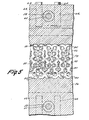
- Figure 1 illustrates one form of a panel structure, generally indicated at 10, constructed in accordance with the principles of the present invention. It will be understood that the panel 10, as shown in Figure 1, (wherein the thickness of the walls is exaggerated), is adapted to be manifolded and used in a radiant energy heat exchanger system.
- the panel structure 10 comprises essentially an extrusion made in accordance with a method embodying the present invention and by the apparatus embodying the present invention which is generally indicated at 12 in Figure 2.
- the panel structure 10 is made of a suitable plastics material and has a uniform cross-sectional configuration throughout its longitudinal extent.
- the essential characteristic of the panel structure is that it includes a multiplicity of parallel passages extending longitudinally therethrough defined by a multiplicity of longitudinally extending integrally interconnected exterior and interior thin wall sections.
- the panel structure 10 Disposed below the upper passages 14 is a multiplicity of intermediate passages 22 defined along their upper peripheries by the upper interior thin wall sections 20, along their sides by downwardly converting vertically extending exterior thin wall sections 24 and along their lower peripheries by lower interior thin wall sections 26.
- the panel structure 10 includes a multiplicity of lower passages 28 disposed below the intermediate passages 22 and defined along their upper peripheries by the lower interior thin wall sections 26 and throughout the remainder of their peripheries by lower generally U-shaped exterior thin wall sections 30.
- a sleeve of coating material 32 is disposed in surface-to-surface engagement with the surfaces defining each of the lower passages 28.
- each outer lens-shaped wall section 16 is approximately two and one half times the width dimension of each passage 34 (or 28 where no sleeves 32 are provided). It will be understood that the number of upper, intermediate and lower passages provided in the panel structure may be varied, depending upon the desired width. An exemplary embodiment is the provision of twenty-seven of each of the upper, intermediate and lower passages.
- the apparatus 12 employed in accordance with the principles of the present invention for making the panel structure 10 as described above includes a combination of components, a first of which is a plastics material feeder assembly, generally indicated at 36, of any known construction.
- the feeder assembly is arranged to receive a supply of plastics pellets at a predetermined dryness and temperature and to continuously impose a melting temperature and extrusion pressure onto the plastics material so that a continuous supply of the fused plastic will be delivered to an extrusion die assembly, generally indicated at 38, at a desired feeder temperature and pressure such that the plastics will flow longitudinally outwardly from the extrusion outlet of the die assembly.
- the apparatus of the present invention also includes a panel handling assembly, generally indicated at 40, disposed within the path of the plastics material moving longitudinally outwardly of the-extrusion outlet of the extrusion die assembly 38 for maintaining the longitudinal movement of the plastic material while reducing the temperature and controlling the exterior configuration of the plastics material until the same has cooled sufficiently to be self-sustaining.
- the apparatus 10 also includes a sprayer assembly 42 for applying an additional coating to the exterior surfaces of certain exterior thin wall sections of the panel structure 10.
- the feeder assembly 36 constitutes essentially a known unit available on the commercial market. Any unit of suitable capacity may be utilized, an exemplary embodiment is the Pacemaker (Trade Mark) III Model 30/1 L/D made by NRM Corp. It will be understood that the unit includes the usual feeder hopper 43 which serves to direct the supply of plastic pellets to a feeder screw chamber where the plastic is moved along by the screw feeder while being continuously subjected to increasing temperature and pressure conditions. The outlet of the feeder assembly 36 is directly connected to the inlet of the die assembly 38.
- the die assembly 38 includes a manifold block 44 having a lateral inlet shown in phantom lines at 46 in Figure 4, which Figure is shown in left-to-right reversal with respect to Figures 2 and 3 communicating with the outlet of the feeder assembly 36.
- a manifold space or main passage 48 which communicates forwardly in forwardly diverging relation, as indicated at 50, with one side of a flat screen pack 52 suitably mounted, as by bolts 54, on the rear surface of a main extrusion block 56.
- Taper frame adapter 51 provides a smooth flow path for entry into section 56.
- the manifold block 44 is connected to the main extrusion block 56 in front-to-back abutting relation by a multiplicity of upper and lower bolt assemblies 58 extending through appropriate openings in the upper and lower portions of both blocks.
- the bolt assemblies provide a conventional securing function and in addition provide cavities for receipt of heating elements 60.
- Extending vertically inwardly from the top of both blocks and upwardly from the bottom of both blocks is a multiplicity of spaced bores 62 within which are mounted temperature sensing units 64. As shown, there is a temperature sensing unit 64 spaced between adjacent bolts 58 both in the upper rear portion of the manifold block 44, upper portion of the extrusion block 56, the lower rear portion of the manifold block 44, and the lower portion of the extrusion block 56. It will be understood that the temperature sensing devices 64 are connected through suitable circuitry of conventional nature to control the energization of the heating units 60 so as to maintain the temperature of the plastics material within the manifold space 48 which flows into the screen pack 52 at a desired controlled temperature hereinafter to be more fully described.
- the screen pack 52 preferably consists essentially of three screens assembled together in series, the downstream one of which is a 40x40 stainless steel screen, the intermediate one of which is an 80x80 stainless steel screen and the upstream one of which is a 100x100 stainless steel screen.
- the forward end of the extrusion block 56 which constitutes the outlet end thereof has formed therein a multiplicity of interconnecting slots corresponding generally in number and position to the multiplicity of thin wall sections in the panel structure 10 as described above.
- the interconnecting slots which make up the extrusion outlet are best shown in Figure 7 and it will be noted that the interconnected slots are preferably oriented in an inverted relation with respect to the orientation in which the resultant panel structure is actually used.
- a multiplicity of interconnected top forming slots 66 which are oriented at the lower part of the outlet but which correspond in configuration and number to the upper thin wall sections 16 of the panel structure 10.
- the top forming slots 66 interconnect with a multiplicity of side forming slots 68 which correspond with and form the thin wall sections 18 of the panel.
- the ends of the slots 68 are communicated by a series of interior slots 70 which correspond with and serve to form the upper intermediate interior thin wall sections 20.
- the ends of the slots 70 also communicate with upwardly converging slots 72 which correspond with and form the exterior thin wall sections 24 of the panel structure 10.
- the upper ends of the slots 72 are interconnected by a series of slots 74 which correspond with and form the lower intermediate interior thin wall sections 26.
- the ends of the slots 74 are connected with the ends of inverted U or V-shaped slots 76 which corresponds with and forms the lower exterior U-shaped thin wall sections 30 of the panel.
- the interconnected slot configuration as described above may be formed by casting techniques or preferably formed in the forward outlet end of the extrusion block 56 by an electrochemical or electronic discharge machine so as to extend inwardly into the block a short distance.
- the interior of the interconnected slots is communicated with the plastic flowing through the screen pack 52 by a multiplicity of bores 78 formed by casting techniques or preferably drilling from the rear end of the extrusion block into communication with the inner ends of the slots in a configuration as best shown in Figure 6.
- Each bore 78 is formed by casting techniques or preferably by drilling or boring operation and a frustoconical counterbore 80 (see Figure 5) is provided in the rearward portion of each bore to aid in directing the plastic flowing through the screen pack 52 into the bores 78.
- each manifold opening is in the form of a bore extending transversely within the extrusion block 56 at positions above or below the plastic flow bores 78.
- Each manifold opening is supplied with a fluid from a supply container or the like, indicated schematically in Figure 2 by the corresponding reference numeral with a subscript s, and has the fluid pressure supplied thereto controlled by a suitable control valve or regulator, indicated schematically in Figure 2 by the corresponding reference numeral with a subscript c.
- An exemplary gas pressure regulator is the type 10B regulator made by Bello- fram Corp. (see U.S. patent No. 2,879,783).
- the manifold opening 82 constitutes a fluid manifold for the flow of fluid onto the exterior thin wall sections 30 and 24 which define the operative bottom of the panel structure but are preferably oriented in an upwardly facing direction as the panel structure moves outwardly of the slotted extrusion outlet.
- a multiplicity of fluid outlet openings 92 is formed in the forward outlet end of the extrusion block 56 above the inverted U-shaped slots 76.
- Each fluid outlet 92 extends from a position above the central portion of each inverted U-shaped slot 76 inwardly to the associated manifold opening 82.
- each outlet opening 92 is adjustably controlled by an adjusting set screw 94 threadedly engaged within the upper portion of the extrusion block 56 so that its conical inner end can be moved relatively into and out of the flow of fluid from the manifold 82 outwardly through the associated outlet opening 92.
- the fluid manifold 84 is formed in the lower forward portion of the extrusion block 56 more or less vertically below the fluid manifold opening 82.
- This manifold opening communicates with the inner end of a multiplicity of outlet openings 96 which open to the forward outlet end of the extrusion block 56 at positions below the top forming slots 66.
- Each of the fluid outlet openings 96 is also provided with an individual control in the form of an adjusting set screw 98 having a conical end adapted to enter within the opening an amount determined by the position of movement of the set screw.
- the manifold opening 86 communicates with a multiplicity of outlet openings 100 each of which extends from the manifold opening 86 to the outlet end of the extrusion block 56 at a position within an associated group of interconnected slots 66, 68 and 70 which serve to form the associated thin wall sections 16, 18 and 20 of the panel structure defining the associated top passage 14. Fluid within the manifold opening 86 therefore flows from the manifold opening 86 longitudinally outwardly of each outlet 100 into each top or upper passage 14 in the panel structure as the latter is formed and moves away from the die assembly.
- outlet passages 100 are formed by casting techniques or preferably by drilling a horizontal bore rearwardly into the forward outlet face of the extrusion block 56 and drilling an intersecting inclined bore upwardly from the bottom of the extrusion block 56 through the laterally extending manifold bore 86, the outer end of each of the inclined bores being counter-bored, threaded and plugged, as indicated at 102.
- the manifold opening 88 has communicated therewith a multiplicity of outlet openings 104 which extend from the manifold opening 88 to the forward outlet end of the extrusion block 56.
- each outlet opening 104 is positioned within an associated group of interconnected slots 70, 72 and 74 which serve to form the associated thin wall sections 20, 24, and 26 of the panel structure defining the associated intermediate passage 22.
- fluid within manifold opening 88 flows therefrom longitudinally outwardly of each outlet opening 104 into an associated passage 22 of the panel structure being formed and moving longitudinally away from the die assembly.
- each outlet opening 104 is formed by drilling a bore rearwardly from the forward outlet face of the extrusion block 56 and an intersecting upwardly extending bore through the laterally extending manifold opening 88. The outer end of each of the latter bores is counter-bored, threaded and plugged, as indicated at 106.
- Fluid manifold opening 90 is communicated with a multiplicity of vertically extending bores 108, each of which is formed by drilling downwardly from the upper surface of the extrusion block 56 through the manifold opening 90.
- the upper outer end of each bore 108 is counter-bored, threaded and plugged, as indicated at 110.
- the inner end of each bore 108 communicates with the inner end of a fluid outlet tube 112, the opposite end of which extends to the forward outlet end of the extrusion block 56 at a position within an associated group of outlet slots 74 and 76 which serve to form the thin wall sections 26 and 30 of the panel structure defining the associated bottom passage 28.
- each outlet tube 112 Extending inwardly within the extrusion block 56 in surrounding relation with the forward portion of each outlet tube 112 is a counterbore 114.
- An annular seal 116 is mounted within the inner end of each counterbore in surrounding relation to the associated tube 112.
- Communicating with each counterbore 114 at a position between the outer end and seal thereof is one end of an inclined bore 118 which extends through a laterally extending manifold opening 120.
- the outer end of each bore 118 is counter-bored, threaded and plugged, as indicated at 122.
- the manifold 120 is adapted to receive a liquid fluid or second heated plastics material from a second feeder of conventional design, indicated schematically at 124.
- Material from the feeder flows into the manifold 120 outwardly thereof into bores 118 and from the bores 118 into the associated counterbores 114 in surrounding relation to the associated tubes 112.
- An extrusion cone 126 is fixed in surrounding relation to the associated tubes 112.
- Extrusion cone 126 is fixed in surrounding relation to the outer end of each tube 112 so as to define a thin annular slit- shaped outlet which serves to evenly distribute the material so provided into a sleeve 32 positioned within the passage 28 of the panel structure being formed.
- the panel handling assembly 40 includes a main base plate 128 which is fixed to the upper surface of a suitable table 130 or the like. Extending upwardly from the base plate 128 and rigidly secured thereto is a pair of parallel vertical mounting plates 132. Each mounting plate has journaled in the central portion thereof one end of a shaft 134. A circular cam 136 is fixed to each end portion of the shaft 134 inwardly of the associated plate 132 so as to be disposed within a rectangular opening 138 formed in an associated side plate 140, Each of the mounting plates 132 is formed with a pair of parallel vertically extending slots 144 on opposite sides of the rectangular opening 134 which receive therein bolt assemblies 146 threadedly engaged within the associated side plate 140.
- side plates 140 can be adjusted vertically with respect to the mounting plates 132 and table 130 by loosening bolt assemblies 146 and turning shaft 134. After the appropriate adjustment has been made bolt assemblies 146 are tightened to maintain the side plates 140 in fixed adjusted relation with respect to the mounting plates 132.
- each of the rollers 148 is formed with an annular peripheral surface 150 having a configuration which, in cross-sectional profile, corresponds with the cross-sectional profile of the exterior surfaces of the top thin wall sections 16 of the panel structure. It will also be noted that each of the rollers 148 is hollow and is provided with a through passage 152 ( Figure 9).
- a suitable liquid dispensing tray 153 is also supported by base plate 128 and provides liquid wetting of at least one lower profile roller 148 which, as shown, is the roller nearest to the extrusion block 56. Liquid solution within the tray 153 is thus carried into contact with exterior surfaces of the top thin wall sections 16 of the panel structure.
- a heat exchange fluid inlet manifold block 154 Mounted alongside one of the side plates 140 is a heat exchange fluid inlet manifold block 154 having an inlet 156 which is adapted to receive heat exchange fluid, which preferably is water, from an appropriate source (not shown).
- heat exchange fluid which preferably is water
- Other heat exchange fluid selections contemplated are freon, silicone oil and glycol.
- the inlet manifold block 154 is communicated with the interior passage 152 of the adjacent side of each of the rollers 148 by means of appropriate rotary fittings 158.
- An outlet manifold block 160 of similar construction to the inlet manifold block 154 is mounted alongside the other side plate 140 and has an outlet connection 162 for returning the heat exchange fluid to a suitable source for handling the same (not shown).
- the outlet manifold block 160 like the inlet manifold block 154, is communicated with the passages 152 of each of the rollers 148 by a series of rotary fittings 164 connected between the adjacent ends of the rollers 148 and the manifold block 160.
- each of the rollers 148 is formed with a hub extension 166 on one end thereof to which is fixedly mounted a spur gear 168.
- the spur gears 168 are driven in a clockwise direction as viewed in Figure 3, so that the upper peripheries of the rollers 148 move in a direction longitudinally away from the die assembly 38 by a series of idler gears 170 suitably journaled on the associated side plate 140. As shown, there are five idler gears 170 provided, each idler gear meshing with two spur gears 168 disposed thereabove.
- main drive spur gear 172 meshing with the adjacent spur gear 170.
- Main drive spur gear 172 is fixed to a drive sprocket 174 which is adapted to be driven by a chain 176 which, in turn, is driven by a suitable motor 178 driving sprocket 170 about which the chain 176 is trained.
- motor 178 which can be a variable speed motor or which can be provided with a speed adjusting transmission, rollers 148 will be rotated in the same longitudinally forward direction at the desired speed selected.
- each fixed side plate 140 is a movable side plate 182.
- a series of upper rollers Suitably journalled between the plates 182 is a series of upper rollers, generally indicated at 184.
- Each of the rollers 184 is adapted to cooperate with a corresponding one of the rollers 148 so as to provide a pair of cooperating rollers engaging the upper and lower exterior surfaces of the panel structure as it moves longitudinally outwardly of the extrusion die assembly 38.
- each of the rollers 184 is formed with an exterior peripheral surface 186 having a configuration which, in cross-sectional profile, corresponds with the cross-sectional profile of the bottom exterior surface of the thin wall sections 30 of the panel structure.
- the rollers 184 are formed with cooling fluid passages 188 extending longitudinally therethrough, one end of which communicates with an inlet manifold block 190 similar to the inlet manifold block 154.
- the inlet manifold block 190 includes a fitting 192 enabling the same to be connected with a source of cooling fluid and a plurality of rotary fittings 194 interconnected between the inlet manifold block 190 and the ends of the rollers 184.
- an outlet manifold block 196 communicates with the opposite ends of the roller passages 188 through rotary fittings 198.
- the outlet manifold block 186 has an outlet fitting 200 connected therewith for returning the cooling fluid to a suitable return source (not shown).
- the movable side plates 182 which are connected to move together by virtue of the mounting of the rollers 184 therebetween are mounted on the upper edge of the fixed side plates 140 by a pair of balls 202 seated within the appropriate recesses in the upper rearward surface of the associated movable side plate 182.
- a rod 204 extends downwardly through an appropriate opening in the rearward end of each movable side plate 182 and is threadedly engaged in fixed relation within the rearward end of the associated fixed side plate 140.
- the upper end of each rod extends above the end of the associated movable side plate 182 and has its upper end threaded to receive a wing nut 206.
- each wing nut 206 and the upper surface of the associated movable side plate 182 in surrounding relation to the associated rod 204 is a coil spring 208 which serves to apply a resilient downwardly acting biasing force on the rearward end of the associated movable side plate 182 tending to cause the same to pivot about the axis of the ball 202 in a counterclockwise direction as viewed in Figure 3.
- each movable side plate 182 is adjustably releasably fixedly attached to the forward end of the associated fixed side wall 140 by a mechanism, generally indicated at 210, which is shown in detail in Figure 10.
- the forward end of each movable side plate 182 is formed with a vertical opening 212.
- a gimbel element 214 mounted within the upper portion of the opening 212 is a gimbel element 214 in the form of a collar having its interior periphery threaded and a pair of pivot pin portions extending in diametrically opposed relation from the exterior periphery thereof which seat within appropriate upwardly facing grooves in the upper surface of the side plate 182 in communication with the opening 212.
- a threaded stem 216 having a knurled knob 218 on the upper end thereof is threadedly engaged within the gimbel 214.
- Formed in the exterior periphery of the lower end of the threaded stem 216 is an annular groove 220 which is adapted to engage within a vertical bore 222 formed within the upper end of the associated fixed side plate 140.
- a pull pin 224 is removably extended within an appropriate transverse opening in the side plate 140 in a position to engage within the annular groove 220.
- a slotted plate 226 is removably fixedly attached to the upper surface of the movable side plate 182, as by a bolt 228, so as to prevent upward movement of the gimbel 214.
- each upper roller 184 is driven at the same speed and in the same direction, namely a direction in which the lower periphery moves in a longitudinally outward direction with respect to the die assembly, in a manner similar to the movement of the lower rolls 148.
- each upper roller 184 includes an extended hub portion 230 at one end having a spur gear 232 fixed thereto.
- the spur gears 232 are drivingly interconnected by means of five idler gears 234 suitably journaled on the associated movable side plate 182, each idler gear being positioned above and between two adjacent spur gears 232 in meshing engagement therewith.
- the upper rollers 232 are driven by a spur gear 236 fixed to the rearwardmost spur gear 232 and disposed in meshing engagement with a cooperating spur gear 238 fixed with respect to the rearwardmost spur gear 168 associated with the rearwardmost roller 184.
- Sprayer assembly 42 preferably consists of a series of fan-shaped spray forming nozzles 240 of conventional "airless" construction mounted, as by a mounting tube 242 fixed between the rearward portions of the movable side plates 182, so as to dispose the discharge outlets of the spray nozzles above and between the rearwardmost upper roller (that nearest to the extrusion block 56) and the next adjacent upper roller. Rollers 184 thus provide even distribution of the applied coating.
- the inlets of the fan-shaped spray forming nozzles 240 are connected with a line 244 connected with a source of spray liquid under pressure (not shown).
- the cooperative operation of the panel handling assembly 40 and extrusion die assembly 44-56 is such that as the extruded panel structure leaves the forwardmost pair of rollers, the thin wall sections thereof are sufficiently cooled to be self-sustaining and use of the heat thus removed promotes the numerous chemical process reactions described herein.
- further handling equipment would be provided, as for example, an adjustable haul-off device for providing a positive controlled movement for the panel structure at a position downstream.
- an appropriate cross-cutting mechanism would be provided for cutting the panel struc- t ure into appropriate lengths.
- such cutting mechanism is appropriately mounted on a longitudinally reciprocable carriage, the cutting element such as a laser, a hot wire or thin band saw blade being reciprocated transversely on the longitudinally reciprocating carriage.
- the cutting element such as a laser, a hot wire or thin band saw blade being reciprocated transversely on the longitudinally reciprocating carriage.
- die assembly 44-56 and roller assembly 12 would be disposed to extrude the panel at a steep downward or vertical inclination. Operation at steep inclinations enables fluids such as silicone oil to drain through the panel, while performing cooling and coating carrier functions, to a sump (not shown) for recovery and recirculation.
- the present apparatus a structural arrangement for performing procedural steps on plastics materials through which highly desirable physical and chemical characteristics can be economically imparted to the resultant panel structure.
- variables in the initial plastics material utilized in the feeder assembly 36 to form the panel structure include the optional use of the secondary fluidized material in the feeder 124 for the interior sleeves 32, the provision of appropriate gaseous or vapor or liquid materials within the manifold openings 82, 84, 86, 88 and 90, and the composition of the liquid spray used within the sprayer assembly 42.
- the fluid selected for circulation through manifold openings 82, 84, 86, 88 and 90 can be high boiling point mineral or silicone oils with certain active ingredients more fully illustrated below.
- a preferred embodiment of the plastics material for many applications is polycarbonate.
- This material presents a desirable blend in the various qualities desired in a solar energy panel structure such as a high melting point, high transparency to solar energy frequencies, resistance to ultraviolet deterioration, impact resistance, recoverability after use, present raw material availability and cost.
- the material selected for use in forming the panel structure should possess the above characteristics to a high degree or should be capable of having such characteristics enhanced in an easy and economical fashion by suitable additives or composited coatings.
- Polycarbonate presents a desirable high melting point, is highly transparent presenting only a 3% loss when fabricated according to the preferred methods described herein and is highly impact resistant.
- Impact resistance is important in order to enable the panel structure to be handled during shipping and installation, as well as to resist the effects of hail and the like once installed.
- Polycarbonate also is highly recoverable after use and its cost is not prohibitive, although other plastics material are considerably less expensive.
- the solar collector described herein is able to deliver more than 800 times as much energy in its first service life as could be delivered if the same plastic were burned in a conventional electric power plant and the electric energy were delivered through conventional power grids.
- Polycarbonate's ability to resist ultraviolet radiation is easily enhanced by adding ultraviolet active material thereto and its tendency to be unstable in water under stress can be alleviated and its resistance to stress corrosion enhanced by suitable additives.
- the procedures which are employed in making the panel structure will desirably vary depending upon the end use or type of system in which the panel structure is to be used.
- the two upper passages 14 and 22 of the panel structure are used as insulating air spaces and the lower passages 28 are used to circulate the water medium
- the addition of an expensive, thick sleeve lining 32 within the lower passages 28 is not regarded to be essential.
- Such sleeve linings would be provided in commercial installations where the fluid being circulated in the lower passages 34 might well contain chemicals which require a much more inert plastic material.
- Alternate working fluids for sourcing or removing heat during operation of the resulting radiative energy heat exchanger include water- glycol solutions, acids, bases, silicone fluids, dry cleaning fluids, oils of all kinds, salt water solutions of all kinds, alcohols, and suspensions of magnetically separable particles compounded to produce energy conversion and aesthetic effects.
- polycarbonate is utilized as the primary plastic material for forming the panel, however, the polycarbonate utilized is mixed with 1/2% to 2% by weight of a suitable fluorescent dye additive such as CYASORB@.
- a suitable fluorescent dye additive such as CYASORB@.
- This ingredient enhances the resistance of the polycarbonate to deterioration from ultraviolet rays. It is important to note, however, that ultraviolet deterioration resistance preferably is imparted not by blocking ultraviolet radiations from entering the plastic material, but rather by permitting such radiation energy to pass through the material at a shifted or increased wavelength.
- the addition of the fluorescent dye additive CYASORB@ to the polycarbonate serves to shift wavelengths passing therethrough of 0.25-0.37 ⁇ m (microns) to 0.4-2.0 ,am (microns).
- the desirability of wavelength shifting from the shorter ultraviolet and visible range to the longer visible and infrared range is thus a desirable characteristic and should be borne in mind in the subsequent procedures hereinafter set forth.
- the wave shifter additive noted above is preferably embodied in the base material itself and further incorporated in the liquid within the tray 153 as will become more apparent hereinafter.
- the pellets Prior to being fed to the feeder assembly 36 the pellets are dried for several hours at a temperature of 121°C (250°F) in a hopper with hot desiccated air constantly blowing therethrough.
- the feeder assembly 36 is operated such that there exists at the outlet a pressure of approximately 482.6 bar (7000 psi) and a temperature of 260°C (500°F).
- the operating psi may be varied from approximately 137.9 bar (2000) psi to approximately 827.4 bar (12000 psi) and the temperature may be varied from approximately 238°C (460°F) to approximately 277°C (530°F).
- the temperature controls within the die assembly 38 are set to maintain the plastic material passing therethrough at 260°C (500°F).
- a range of variation between approximately 249°C (480°F) to approximately 271 °C (520°F) can be effected.
- the pressure of the plastics material within the die adjacent the outlet is 275.8 bar (4000 psi) and here again a range can be employed of approximately 137.8 bar (2000 psi) to approximately 413.7 bar (6000 psi).
- a further important aspect of the present invention is to supply to the polycarbonate material being processed through the feeder further additives which will enhance the stress corrosion resistance of the polycarbonate material.
- Stress corrosion responses in polycarbonate material without the present additive are characterized by cracking, pitting, loss of ductility, and weight loss by mass fall-out of exposed areas. These responses are noted as attacks following stepwise polymer bond breakage. These responses are more pronounced in the presence of residual or induced stress and increase with increasing temperature environments, as for example, environments in excess of 60°C (140°F) which can be presented in radiant energy heat exchange systems.
- a supply pipe 246 is provided for the purpose of introducing or supplying the further additive to the polycarbonate material within the feeder at a position therein after the solid pellets of material have been heated but before the material has reached its fusion temperature.
- a preferred additive is a 2-20% by weight of a trimethylchlorosilane vapor mixed with 98-80% dry nitrogen.
- the vapor mixture is fed at room temperature at a pressure of approximately 5.171 bar (75 psi) at a position such that it will contact the resin within the feeder at a temperature of approximately 38°C (100°F) to 260°C (500°F).
- the vapor mixture chemically reacts with dried polycarbonate resin, particularly as it fuses, so that the polycarbonate end group produces a polycarbonate without stress corrosion susceptible areas.
- the supplying of the stress corrosion resistant additive in the feeder is shown schematically. It will be understood, however, that it is within the contemplation of the present application to utilize feed pellets which have previously been treated with the additive in the feeder of the present invention.
- the fluid fed to the manifold onenina 82 which impinges on the operative bottom surface of the panel structure is preferably 100% dry air. It is maintained at a pressure of 1.379 bar (20 psi) and at room temperature. Variation in the temperature is possible, although since room temperature is entirely adequate, variation is not usually necessary.
- the pressure can be varied as desired, for example, from 0.678 to 2.068 bar (10 to 30 psi).
- the fluid fed to the fluid manifold opening 84 is preferably 90% to 98% dry nitrogen mixed with 2% to 10% trimethylchlorosilane.
- This gaseous mixture has been found effective starting at room temperature and it is maintained at a pressure of 0.689 bar (10 psi).
- the pressure can vary as desired, for example, from 0.345 to 1.034 bar (5 to 15 psi).
- the fluid fed to the fluid manifold opening 86 is preferably 100% dry air at room temperature.
- the appropriate control 86c is set to maintain the gas pressure at approximately 172 mbar (2.5 psi).
- the gas which flows outwardly of the outlets 100 into the upper passages 14 of the panel structure is essentially inert since in the preferred operative embodiment these passages merely contain insulating air.
- the fluid which is fed to the fluid manifold opening 88 is a mixture of 85 to 97% nitrogen and 3 to 15% silicon tetrahydride.
- the gas is fed to the manifold opening 88 at room temperature and is maintained by the associated control 88c at a pressure of approximately 241 mbar (3.5 psi). Since the mixture fed to the manifold 88 flows outwardly of the outlet openings 104 into the intermediate passages 22 of the panel structure being formed while the latter is hot, there is a chemical conversion which takes place, resulting in the application of a molecular coating of a silane to the interior surfaces of the thin wall sections 20, 24 and 26, defining the interior openings 22.
- This molecular coating has the characteristic of shifting radiant energy within the range of 0.2 to 0.7 pm (microns) to wavelengths of 1.8 ⁇ m (microns) and above.
- sleeves 32 are not utilized within the passages 28 and consequently outlets 126, fluid passages 114 and 118, manifold opening 120 and auxiliary fluidized medium feeding device 124 are not utilized.
- the fluid fed to the manifold opening 90 is a mixture of 75 to 98% by weight of nitrogen and 2 to 25% of tetrafluoroethylene.
- the gas is supplied at room temperature and maintained at a pressure of approximately 345 mbar (5 psi). Since the gaseous mixture within the manifold opening 90 passes outwardly from the outlet end of the tubes 112 into the passages 28 directly into contact with the interior surfaces of the thin wall sections 26 and 30 defining the passages 28, there is an immediate in situ polymerization of the TFE which applies a molecular coating of polymerized TFE to the interior surfaces of the thin wall sections 26 and 30 defining the passages 28. This molecular coating also provides resistance to aqueous attack and enhances the stability of the polycarbonate material exposed to other fluid solvents.
- a preferred liquid spray which is fed to the spray forming nozzles 240 at a preferred pressure of approximately 172.4 bar (2500 psi) and at room temperature, is a latex mixture having a solids content of 40% by total weight (within a range of 15-65%) which applies a water vehicle coating to the exterior surface of the panel forming the bottom thereof in operation.
- a preferred composition of the mixture includes a resinous carrier ingredient, a latex forming ingredient, and an active waveshifting ingredient.
- a resinous carrier ingredient a latex forming ingredient
- an active waveshifting ingredient a preferred list of ingredients on a % of solids basis which includes two resinous carriers.
- the coating is totally opaque to radiant energy of all wavelengths. Solar energy of all wavelengths is absorbed and re-radiated, however, within the region of between 0.4 ⁇ m and 20 I tm (microns) into the infrared range. This re-radiated energy is, because of the panel's geometry, focused upon the working fluid.
- Liquid applied from tray 153 is preferably a water clear latex of terpolymer consisting of 10-25% solids of chlorotrifluoroethylene, 50-75% solids of polyvinylidenefluoride and 15-26% solids of polyvinylidene chloride in a liquid component consisting of 49% distilled water and 48.5% Dow XC 7080 and 1.5% Dow Epoxy product DER (Trade Mark), the solid to total ratio being between 25%-50% solids.
- rollers 148 provide the combined function of introducing the latex on surfaces 16 (pretreated through a gas phase reaction) and evenly rolling the applied latex to a dense even film.
- the function of the clear resulting dried terpolymer film is to provide a low index of refraction, scratch and chemical resistant coating and to serve as a vehicle for certain fluorescent dye additives.
- the exterior surfaces of the plastic material are immediately contacted by the first set of rollers 148 and 184 having circulating therethrough a heat exchange fluid medium, preferably water, maintained at near room temperature.
- a heat exchange fluid medium preferably water
- the exterior thin wall sections 16, 24 and 30 are at a temperature which is sufficiently high that they are not self-sustaining.
- the interior thin wall sections 20 and 26 are likewise at an elevated temperature such that they are not self-sustaining.
- the above-described interior passage pressures also serve to maintain contact of the exterior thin wall sections 16 with the roller surfaces 150 and the exterior thin wall sections 24 and 30 with the exterior surface 186 of the rollers 184.
- the spacing between successive pairs of rollers 148 and 184 progressively diminishes so that a slight change in the exterior configuration of the panel structure is provided during the movement through all of the pairs of rollers. This assures dense, even, completely cured out coatings, and close geometrical control of the panel geometry.
- the exterior thin wall sections are essentially self-sustaining.
- the interior thin wall sections are either simultaneously made self-sustaining or become so shortly thereafter.
- the coatings provided by the application of the fluids as well as the application of the liquid spray and roller coating are made possible and enhanced by virtue of their being applied while the plastic is near its highest temperature.
- the coating applied by the sprayer assembly 42 is particularly tenacious in that the particles by virtue of the heat within the plastic material are maintained in efficient adhesion and compression through an after heating phenomenon as the interior wall sections are finally cooled to uniform panel temperature.
- the main plastics material which is fed to the feeder assembly can be, in place of the preferred polycarbonate material, any one of the following materials: polychlorotrifluoro- ethylene, polypropylene, polymethylpentene, polymethyl methacrylate (limited to an operating temperature not over 125°C) and other acrylates, 7-30% polyvinylidene fluoride- polymethyl methacrylate alloys, polysulfones, e.g. polyether sulfone polyarylsulfone, Bisphenol A-sulfone or Hydroquinone sulfone, and thermoplastic silicones.
- the ultraviolet stabilizer in place of CYASORB (Trade Mark) 5411 can be 6,13-dichloro - 3,10 - diphenyltriphenodioxazene, TINUVIN P (Trade Mark) or other conventional UV stabilizer.
- halogenated organosilanes may be utilized, for example, the family of chlorodiphenylsilane, hexamethyldisilane, vinyltrichlorosilane, trimethylbromo- silane, triethylchlorosilane, hexaethyldisilane and dimethyldichlorosilane.
- nitrogen air or other inert gases may be utilized.
- Fluids which can be fed to the manifold opening 82 other than the preferred 100% dry air include nitrogen, argon, helium, oxygen, carbon dioxide or other gases inert under the treatment conditions.
- Fluids which can be fed to the manifold opening 84 other than the mixture of trimethylchlorosilane and nitrogen include methyltrichlorosilane or dichlorodimethylsilane mixed with dry air or other inert gas, as indicated above.
- Gases which can be fed to the manifold opening 86 other than the 100% dry air are nitrogen, argon, helium, oxygen, carbon dioxide and other gas inert under the treatment conditions.
- Gases which can be fed to the manifold opening 88 other than the mixture of nitrogen or other inert gas and silicontetrahydride are mixtures of nitrogen or other inert gas with trimethylchlorosilane, methyltrichlorosilane, dichlorodimethylsilane or silicontetrachloride.
- inert gas and dilutant there can be used oxygen, helium or carbon dioxide.
- auxiliary plastics which can be utilized to provide desired optical functions, chemical resistance, or improved heat transfer are: melted polysulfone, polyvinylidenefluoride, chlorotrifluoroethylene, poly- methylpentane, polypropylene; latex coatings of polyvinylidene chloride, varnishes of the aforesaid in suitable solvents; thermovinylizing plastisols and organosols; silicone emulsions and dispersions; and dye colorants in any of the aforesaid vehicles.
- latexes, varnishes, adhesive preparations and thermoplastics would be applied through manifold 78 to passages 28 for purposes of holding in place fibers, whiskers, and particles carried by gaseous or liquid fluids through 90 to form high surface-to-volume coatings for improved radiant energy conversion to heat.
- Fibers particularly useful for this purpose are AI Z O 3 ; BeO; SiC; B 4 C; Si 3 N 4 ; and graphite. Materials entered into passages 28 through 90 and 78 may produce high surface to volume deposits rather than molecular coatings.
- a particularly useful solar collector for heating gaseous working fluids is prepared by admitting suitable liquid adhesives such as allyl diglycol carbonate (CR-39), diallyl phthalate (DAPON (Trade Mark)) urethane, or epoxy through 78 and suitable fibers or whiskers such as carbon, A1 2 0 3 1 Zr0 2 , SiC, aluminium, or BN through 90 in a gas stream.
- suitable liquid adhesives such as allyl diglycol carbonate (CR-39), diallyl phthalate (DAPON (Trade Mark)) urethane, or epoxy
- suitable fibers or whiskers such as carbon, A1 2 0 3 1 Zr0 2 , SiC, aluminium, or BN
- Carbon filaments preferably of a curved form about 12.7 It m (0.0005 inches) diameter by about 0.508 ⁇ m (0.020 inches) in length are blown through 90 in a stream of air or other inert gas and deposited upon the curing adhesive.
- the preferred carbon filament is prepared by thermal degradation of organic rayon filament.
- the heat available from the panel walls rapidly sets the thin adhesive and the deposited fibers may be largely oriented as whiskers standing against the inside surface of the panel.
- the resulting coating of adhesive and whisker deposit converts 30% or more of the incoming light penetrating 26 to heat on whiskers immediately below 26. About 70% of the light passes to the remaining whisker coating surfaces where it is converted to heat. Gaseous working fluids circulated within passages 34 are thus exposed to a high surface to volume fibrous coating for maximum heat transfer.
- thermoset coating 32 geometry Any number of variations of the coating 32 geometry are possible by machining the head of tube 112. Entry gaps may be for top, bottom, or side coating passages 28.
- a particularly useful deposit is made by arranging the gap between 112 and 114 to be an eccentric crescent shaped geometry, having maximum gap of about 0.152 mm (0.006 inch) near one end.
- Thermosetting liquid plastisols such as allyl diglycol carbonate or diallyl phthalate, because of unequal flow rates through the eccentric crescent, tend to form spiral shaped fins against the walls of passages 28.
- the lead of the spiral end resulting spacing between the helical ridge of the spiral is dependent upon the pressure and viscosity of the entering thermoset.
- the thermoset coated areas may be further coated with whisker or particle deposits from air streams conducted through 90 as previously described. Dyes and fillers may also be incorporated in the thermoset liquids for optical and heat transfer effects.
- Gases fed to the manifold opening 90 other than the mixture of nitrogen and tetrafluoroethylene are a mixture of other inert gas, e.g. argon, helium or carbon dioxide with tetrafluoroethylene, hexafluoropropylene, acetylene plus fluorine or chlorotrifluoroethylene.
- compositions of the liquid spray from the specific example previously given are also contemplated.
- kerosene or paraffin alcohols can be utilized, such as methanol, ethanol, propanol and isopropanol.
- acrylic and polyvinylfluoride resinous carriers previously listed, which may be used singly if desired, the following resinous carriers can be used, either singly or in combination: tetrafluoroethylene: chlorotrifluoroethylene, hexafluoropropylene, or polyvinylidene chloride.
- polymethacrylatesiloxane latex forming ingredient there can be used methylcellosolveacetate.
- resinous latex compositions can be utilized in which case there would be no need for a separate latex forming ingredient, for example, the acrylic latex Dow XC7080, the epoxy latex Dow DER-mixed with DER732 or Rohm Et Haas RHOPLEX (Trade Mark) which is an aminohydrochloride salt of an acrylic resin.
- a separate latex forming ingredient for example, the acrylic latex Dow XC7080, the epoxy latex Dow DER-mixed with DER732 or Rohm Et Haas RHOPLEX (Trade Mark) which is an aminohydrochloride salt of an acrylic resin.
- the zinc sulfide solid solution active ingredient there can be utilized an iron sulfide solid solution with a yttrium dopant, zinc oxide, magnesium oxide, calcium phosphate, zirconium oxide, silicon and oxides of silicon, silicon carbide, and iron carbide.
- liquid sprays contemplated include varnish compositions such as chlorotrifluoro- ethylenepolyvinylidene fluoride copolymer solute in acetone or benzol trifluoride solvent, with silicon carbide, iron carbide, and zinc sulfide solid solution fine particle suspensions as optically active ingredients.
- the copolymer forms a film upon evaporation of the solvent and the particle suspension performs absorption-reradiation functions.
- Solar energy ranging from radiation at 0.25,um (microns) through about 2.5,um (microns) is totally absorbed. This energy is reradiated at longer wavelengths ranging from about 0.5 um (microns) through about 12 ⁇ m (microns).
- the same terpolymer can be made as a varnish liquid composition, in which case the preferred solvent is benzotrifluoride with a solids to total ratio ranging between 20 and 60% solids.
- Variations in the terpolymer composition, either latex or varnish include the use of hexafluoropropylene for the polyvinylidene chloride or the substitution of tetrafluoroethylene for the chlorotrifluoroethylene.
Landscapes
- Engineering & Computer Science (AREA)
- Mechanical Engineering (AREA)
- Physics & Mathematics (AREA)
- Thermal Sciences (AREA)
- Life Sciences & Earth Sciences (AREA)
- Sustainable Development (AREA)
- Sustainable Energy (AREA)
- Chemical & Material Sciences (AREA)
- Combustion & Propulsion (AREA)
- General Engineering & Computer Science (AREA)
- Extrusion Moulding Of Plastics Or The Like (AREA)
- Laminated Bodies (AREA)
Priority Applications (1)
| Application Number | Priority Date | Filing Date | Title |
|---|---|---|---|
| AT80900333T ATE8351T1 (de) | 1979-01-26 | 1980-01-24 | Verfahren und apparat zur herstellung einer sonnenzellenstruktur aus kunststoff. |
Applications Claiming Priority (3)
| Application Number | Priority Date | Filing Date | Title |
|---|---|---|---|
| US6754 | 1979-01-26 | ||
| US06/006,754 US4271103A (en) | 1979-01-26 | 1979-01-26 | Plastic solar panel structure and method for making the same |
| AU26788/84A AU2678884A (en) | 1979-01-26 | 1984-04-12 | Plastic solar panel structure |
Publications (3)
| Publication Number | Publication Date |
|---|---|
| EP0022849A1 EP0022849A1 (en) | 1981-01-28 |
| EP0022849A4 EP0022849A4 (en) | 1981-08-27 |
| EP0022849B1 true EP0022849B1 (en) | 1984-07-11 |
Family
ID=34808789
Family Applications (1)
| Application Number | Title | Priority Date | Filing Date |
|---|---|---|---|
| EP80900333A Expired EP0022849B1 (en) | 1979-01-26 | 1980-08-12 | Method and apparatus for manufacturing a plastics solar panel structure |
Country Status (7)
| Country | Link |
|---|---|
| US (1) | US4271103A (enExample) |
| EP (1) | EP0022849B1 (enExample) |
| JP (1) | JPS56500129A (enExample) |
| CA (1) | CA1191314A (enExample) |
| DE (1) | DE3068481D1 (enExample) |
| MX (1) | MX151472A (enExample) |
| WO (1) | WO1980001548A1 (enExample) |
Families Citing this family (27)
| Publication number | Priority date | Publication date | Assignee | Title |
|---|---|---|---|---|
| FR2493219B1 (fr) * | 1980-10-30 | 1984-11-23 | Indumat Sa | Procede et dispositif de fabrication de structures alveolaires en matiere thermoplastique et structures obtenues |
| AT374866B (de) * | 1982-10-13 | 1984-06-12 | Hirsch Elisabeth | Hohlkammerplatte mit im abstand und parallel zueinander angeordnete deckflaechen |
| DE3244953C2 (de) * | 1982-12-04 | 1984-11-29 | Röhm GmbH, 6100 Darmstadt | Verfahren zur Herstellung einer Hohlkammerkunststofftafel |
| DE8235298U1 (de) * | 1982-12-16 | 1983-06-23 | Bayer Ag, 5090 Leverkusen | Stegdoppelplatte |
| US4718404A (en) * | 1986-03-26 | 1988-01-12 | Charlton Sadler | Solar collector apparatus and method |
| US4867133A (en) * | 1986-03-26 | 1989-09-19 | Charlton Sadler | Solar collector method and apparatus |
| DE3736280A1 (de) * | 1987-10-27 | 1989-05-11 | Roehm Gmbh | Verfahren zur herstellung kratzfest beschichteter extrudierter kunststoffbahnen |
| US4884960A (en) * | 1988-05-06 | 1989-12-05 | Allied-Signal Inc. | Die for extruding and wash coating |
| US5882564A (en) * | 1996-06-24 | 1999-03-16 | Andersen Corporation | Resin and wood fiber composite profile extrusion method |
| NO313473B1 (no) * | 2001-10-12 | 2002-10-07 | Solarnor As | Solfangerplate, fremgangsmåte for driftssikring av en solfanger og fremgangsmåte for fremstilling av en solfangerplate |
| WO2003085329A1 (en) * | 2002-04-10 | 2003-10-16 | Neil Christopher Hellmann | A solar panel structure |
| US20040141815A1 (en) * | 2002-11-01 | 2004-07-22 | Jeff Moreau | Fiber re-enforcement of joints and corners of composite sheet piling segments |
| CA2752624A1 (en) * | 2003-08-20 | 2005-03-03 | Sunpower Corporation, Systems | Pv wind performance enhancing methods and apparatus |
| DE102006042711B4 (de) * | 2006-09-12 | 2012-06-14 | Krones Aktiengesellschaft | Verfahren und Vorrichtung zur Herstellung von Kunststoffverpackungsbehältern |
| DE102007004247A1 (de) * | 2007-01-23 | 2008-07-24 | Breyer Gmbh Maschinenfabrik | Verfahren zum Bearbeiten von extrudierten Kunststoffplatten |
| US20090165838A1 (en) * | 2007-01-24 | 2009-07-02 | Beck Wiiliam Bill | Coated solar panel |
| US20100108054A1 (en) * | 2008-11-06 | 2010-05-06 | Ekhoff Donald L | Optically efficient and thermally protected solar heating apparatus and method |
| JP5341706B2 (ja) * | 2009-10-16 | 2013-11-13 | 株式会社ニューフレアテクノロジー | 半導体製造装置および半導体製造方法 |
| US8307606B1 (en) | 2011-07-07 | 2012-11-13 | Solon Corporation | Integrated photovoltaic rooftop modules |
| RU2523616C2 (ru) * | 2012-11-01 | 2014-07-20 | Федеральное государственное бюджетное образовательное учреждение высшего профессионального образования "Пензенский государственный технологический университет", ФГБОУ ВПО "ПензГТУ" | Энергоэффективный солнечный коллектор |
| US9263985B2 (en) | 2012-11-13 | 2016-02-16 | Pi Solar Technology Gmbh | Rooftop photovoltaic modules |
| WO2014144996A1 (en) * | 2013-03-15 | 2014-09-18 | Mcalister Technologies, Llc | Radiant energy collectors and methods therefor |
| EP3070414A1 (de) * | 2015-03-20 | 2016-09-21 | Universität Stuttgart | Solarkollektor und Verfahren zu dessen Herstellung |
| WO2016210339A1 (en) * | 2015-06-25 | 2016-12-29 | Nitto Denko Corporation | Solar water heater element |
| US9628019B1 (en) | 2016-09-09 | 2017-04-18 | Polar Racking Inc. | Photovoltaic panel racking system |
| US10274227B2 (en) | 2016-10-16 | 2019-04-30 | Thomas Richard Wehner | Thermosyphon cooling for overheat protection |
| CN111575618B (zh) * | 2020-05-15 | 2021-07-02 | 江苏理工学院 | 一种降低大形变量轧制Al-Zn合金开裂倾向的处理方法 |
Citations (13)
| Publication number | Priority date | Publication date | Assignee | Title |
|---|---|---|---|---|
| US3212132A (en) * | 1962-10-29 | 1965-10-19 | Sr Edward F Westlake | Apparatus for extrusion molding of thermoplastic rods |
| US3470286A (en) * | 1965-08-09 | 1969-09-30 | Christine Weber | Manufacture of elongated resinous strips |
| US3530535A (en) * | 1966-12-16 | 1970-09-29 | Carrol C Sachs | Linear extruding apparatus |
| US3784345A (en) * | 1970-11-12 | 1974-01-08 | Dynamit Nobel Ag | Apparatus for the extrusion of hollow articles |
| US3851028A (en) * | 1969-04-24 | 1974-11-26 | S Beyer | Method for shaping extrusion-moulded articles made of synthetic plastics material |
| GB1444561A (en) * | 1972-09-22 | 1976-08-04 | Dynamit Nobel Ag | Continuous production of elongate section members |
| US3980071A (en) * | 1974-03-21 | 1976-09-14 | Sunworks, Inc. | Solar energy collector |
| DE2510321A1 (de) * | 1975-03-10 | 1976-09-23 | Gerhard Prof Dr Ing Schenkel | System zur nutzung der sonnenenergie |
| US4021172A (en) * | 1974-05-31 | 1977-05-03 | Plastic & Form Kunststoff-Verarbeitungs-Gmbh | Extrusion apparatus for foil-covered, hollow plastic bodies |
| US4089324A (en) * | 1975-04-26 | 1978-05-16 | N.V. Internationale Octrooi Maatschappij "Octropa" | Heat transfer element |
| US4090497A (en) * | 1976-04-28 | 1978-05-23 | Kelly Donald F | Solar energy system |
| US4099515A (en) * | 1977-06-29 | 1978-07-11 | The United States Of America As Represented By The United States Department Of Energy | Fabrication of trough-shaped solar collectors |
| GB1531608A (en) * | 1975-08-16 | 1978-11-08 | Roehm Gmbh | Stretching process |
Family Cites Families (10)
| Publication number | Priority date | Publication date | Assignee | Title |
|---|---|---|---|---|
| US3038202A (en) * | 1959-01-28 | 1962-06-12 | Multiple Extrusions Inc | Method and apparatus for making multiple tube structures by extrusion |
| US3274315A (en) * | 1963-02-25 | 1966-09-20 | Tokan Kogyo Co Ltd | Process for unitized construction of synthetic resin board or cylinder |
| US3668288A (en) * | 1968-11-18 | 1972-06-06 | Keiichi Takahashi | Method for making thermoplastic synthetic resin hollow structure articles |
| DE2147876C3 (de) * | 1970-09-29 | 1975-04-24 | Tokan Kogyo Co. Ltd., Tokio | Verfahren und Vorrichtung zum Herstellen von Hohlplattenprodukten aus thermoplastischem Kunstharz |
| US3764245A (en) * | 1971-05-10 | 1973-10-09 | F Miyamoto | Apparatus for producing light structural board of thermoplastic resin |
| US3825641A (en) * | 1971-06-04 | 1974-07-23 | L Barnett | Method of forming multiple passageway plastic conduit |
| US3792951A (en) * | 1972-01-24 | 1974-02-19 | Extrudyne Inc | Apparatus for producing extruded hollow board |
| IT1037808B (it) * | 1975-05-02 | 1979-11-20 | Covema Srl | Impianto per la realizzazione particolarmente di profilati cavi in materia plastica |
| IL52272A (en) * | 1976-06-15 | 1979-05-31 | Mcalister Roy E | Solar energy collector |
| US4181487A (en) * | 1977-12-23 | 1980-01-01 | Milton Kessler | Vacuum sizing apparatus |
-
1979
- 1979-01-26 US US06/006,754 patent/US4271103A/en not_active Expired - Lifetime
-
1980
- 1980-01-24 DE DE8080900333T patent/DE3068481D1/de not_active Expired
- 1980-01-24 WO PCT/US1980/000065 patent/WO1980001548A1/en not_active Ceased
- 1980-01-24 JP JP50044580A patent/JPS56500129A/ja active Pending
- 1980-01-25 MX MX180953A patent/MX151472A/es unknown
- 1980-01-25 CA CA000344447A patent/CA1191314A/en not_active Expired
- 1980-08-12 EP EP80900333A patent/EP0022849B1/en not_active Expired
Patent Citations (13)
| Publication number | Priority date | Publication date | Assignee | Title |
|---|---|---|---|---|
| US3212132A (en) * | 1962-10-29 | 1965-10-19 | Sr Edward F Westlake | Apparatus for extrusion molding of thermoplastic rods |
| US3470286A (en) * | 1965-08-09 | 1969-09-30 | Christine Weber | Manufacture of elongated resinous strips |
| US3530535A (en) * | 1966-12-16 | 1970-09-29 | Carrol C Sachs | Linear extruding apparatus |
| US3851028A (en) * | 1969-04-24 | 1974-11-26 | S Beyer | Method for shaping extrusion-moulded articles made of synthetic plastics material |
| US3784345A (en) * | 1970-11-12 | 1974-01-08 | Dynamit Nobel Ag | Apparatus for the extrusion of hollow articles |
| GB1444561A (en) * | 1972-09-22 | 1976-08-04 | Dynamit Nobel Ag | Continuous production of elongate section members |
| US3980071A (en) * | 1974-03-21 | 1976-09-14 | Sunworks, Inc. | Solar energy collector |
| US4021172A (en) * | 1974-05-31 | 1977-05-03 | Plastic & Form Kunststoff-Verarbeitungs-Gmbh | Extrusion apparatus for foil-covered, hollow plastic bodies |
| DE2510321A1 (de) * | 1975-03-10 | 1976-09-23 | Gerhard Prof Dr Ing Schenkel | System zur nutzung der sonnenenergie |
| US4089324A (en) * | 1975-04-26 | 1978-05-16 | N.V. Internationale Octrooi Maatschappij "Octropa" | Heat transfer element |
| GB1531608A (en) * | 1975-08-16 | 1978-11-08 | Roehm Gmbh | Stretching process |
| US4090497A (en) * | 1976-04-28 | 1978-05-23 | Kelly Donald F | Solar energy system |
| US4099515A (en) * | 1977-06-29 | 1978-07-11 | The United States Of America As Represented By The United States Department Of Energy | Fabrication of trough-shaped solar collectors |
Also Published As
| Publication number | Publication date |
|---|---|
| DE3068481D1 (en) | 1984-08-16 |
| MX151472A (es) | 1984-11-29 |
| WO1980001548A1 (en) | 1980-08-07 |
| CA1191314A (en) | 1985-08-06 |
| US4271103A (en) | 1981-06-02 |
| EP0022849A4 (en) | 1981-08-27 |
| JPS56500129A (enExample) | 1981-02-12 |
| EP0022849A1 (en) | 1981-01-28 |
Similar Documents
| Publication | Publication Date | Title |
|---|---|---|
| EP0022849B1 (en) | Method and apparatus for manufacturing a plastics solar panel structure | |
| EP0281447B1 (fr) | Procédé de fabrication de profilés de polymère thermoplastique par pultrusion - appareillage - produits obtenus | |
| USRE34605E (en) | Infrared reflective optical interference film | |
| EP1691964B1 (en) | Method for producing capillar products | |
| US6716522B2 (en) | Molded article from thermoplastic composite material and method for producing the same | |
| US4380570A (en) | Apparatus and process for melt-blowing a fiberforming thermoplastic polymer and product produced thereby | |
| CA1223418A (en) | Webbed multiple sheets | |
| CA1088719A (en) | Process for the sizing of coextruded, multiple-layer extruded profiles from thermoplastic synthetic resins | |
| US4371326A (en) | Apparatus for making plastic solar panel structure | |
| CA1199766A (en) | Method and apparatus for the formation of profiled thermoplastic film | |
| US3847585A (en) | Method for the preparation of multilayer optical filters | |
| US4871487A (en) | Method of making a polymeric optical waveguide by coextrusion | |
| US5122211A (en) | Method for forming thermoplastic composite filament into a structure | |
| US3941550A (en) | Apparatus using solid insulating material as a center plate between multiple flat extrusion streams | |
| US3564651A (en) | Non-stick fluorocarbon resin-surfaced mixing element | |
| US20090174107A1 (en) | Shaping Device and Method for Shaping and Cooling Articles, Especially Hollow Profiles | |
| Abbasian et al. | Investigation on factors affecting stratification phenomenon in epoxy-acrylic coatings | |
| US3275725A (en) | Method of making laminated tubing | |
| CN220638662U (zh) | 氮气保护的etfe挤出流延薄膜生产装置 | |
| EP0448623B1 (en) | Thermoformable polyaryletherketone/polyvinyl fluoride laminates | |
| CA1060172A (en) | Process for producing polymeric film and apparatus therefor | |
| US20050179163A1 (en) | Method in an extrusion process, an extrusion process and an apparatus for an extrusion process | |
| JP2007517235A (ja) | 扁平なプラスチック光ファイバおよびこのようなファイバを用いる照明装置 | |
| US20050123682A1 (en) | Method and device for forming a plastic coat on a surface | |
| GB1589621A (en) | Quench bath |
Legal Events
| Date | Code | Title | Description |
|---|---|---|---|
| PUAI | Public reference made under article 153(3) epc to a published international application that has entered the european phase |
Free format text: ORIGINAL CODE: 0009012 |
|
| 17P | Request for examination filed |
Effective date: 19800919 |
|
| AK | Designated contracting states |
Designated state(s): AT CH DE FR GB LU NL SE |
|
| GRAA | (expected) grant |
Free format text: ORIGINAL CODE: 0009210 |
|
| AK | Designated contracting states |
Designated state(s): AT CH DE FR GB LU NL SE |
|
| PG25 | Lapsed in a contracting state [announced via postgrant information from national office to epo] |
Ref country code: SE Effective date: 19840711 Ref country code: CH Effective date: 19840711 Ref country code: AT Effective date: 19840711 |
|
| REF | Corresponds to: |
Ref document number: 8351 Country of ref document: AT Date of ref document: 19840715 Kind code of ref document: T |
|
| REF | Corresponds to: |
Ref document number: 3068481 Country of ref document: DE Date of ref document: 19840816 |
|
| ET | Fr: translation filed | ||
| REG | Reference to a national code |
Ref country code: CH Ref legal event code: PL |
|
| PG25 | Lapsed in a contracting state [announced via postgrant information from national office to epo] |
Ref country code: LU Free format text: LAPSE BECAUSE OF NON-PAYMENT OF DUE FEES Effective date: 19850131 |
|
| PGFP | Annual fee paid to national office [announced via postgrant information from national office to epo] |
Ref country code: NL Payment date: 19850131 Year of fee payment: 6 |
|
| PGFP | Annual fee paid to national office [announced via postgrant information from national office to epo] |
Ref country code: DE Payment date: 19850225 Year of fee payment: 6 |
|
| PLBE | No opposition filed within time limit |
Free format text: ORIGINAL CODE: 0009261 |
|
| STAA | Information on the status of an ep patent application or granted ep patent |
Free format text: STATUS: NO OPPOSITION FILED WITHIN TIME LIMIT |
|
| 26N | No opposition filed | ||
| PG25 | Lapsed in a contracting state [announced via postgrant information from national office to epo] |
Ref country code: NL Effective date: 19860801 |
|
| GBPC | Gb: european patent ceased through non-payment of renewal fee | ||
| NLV4 | Nl: lapsed or anulled due to non-payment of the annual fee | ||
| PG25 | Lapsed in a contracting state [announced via postgrant information from national office to epo] |
Ref country code: FR Free format text: LAPSE BECAUSE OF NON-PAYMENT OF DUE FEES Effective date: 19860930 |
|
| PG25 | Lapsed in a contracting state [announced via postgrant information from national office to epo] |
Ref country code: DE Effective date: 19861001 |
|
| REG | Reference to a national code |
Ref country code: FR Ref legal event code: ST |
|
| PG25 | Lapsed in a contracting state [announced via postgrant information from national office to epo] |
Ref country code: GB Effective date: 19881118 |