EP0022693A1 - Dispositif électronique de détection d'intrusions dans un environnement - Google Patents
Dispositif électronique de détection d'intrusions dans un environnement Download PDFInfo
- Publication number
- EP0022693A1 EP0022693A1 EP80400935A EP80400935A EP0022693A1 EP 0022693 A1 EP0022693 A1 EP 0022693A1 EP 80400935 A EP80400935 A EP 80400935A EP 80400935 A EP80400935 A EP 80400935A EP 0022693 A1 EP0022693 A1 EP 0022693A1
- Authority
- EP
- European Patent Office
- Prior art keywords
- output
- input
- line
- phase
- amplifier
- Prior art date
- Legal status (The legal status is an assumption and is not a legal conclusion. Google has not performed a legal analysis and makes no representation as to the accuracy of the status listed.)
- Withdrawn
Links
- 238000001514 detection method Methods 0.000 title description 5
- 230000010355 oscillation Effects 0.000 claims abstract description 51
- 239000004020 conductor Substances 0.000 claims abstract description 29
- 230000005540 biological transmission Effects 0.000 abstract description 6
- 238000012937 correction Methods 0.000 description 5
- 230000008901 benefit Effects 0.000 description 3
- 238000001914 filtration Methods 0.000 description 3
- 230000035945 sensitivity Effects 0.000 description 3
- 230000001960 triggered effect Effects 0.000 description 3
- 230000008859 change Effects 0.000 description 2
- 230000004048 modification Effects 0.000 description 2
- 238000012986 modification Methods 0.000 description 2
- 230000003071 parasitic effect Effects 0.000 description 2
- 230000010363 phase shift Effects 0.000 description 2
- 230000004044 response Effects 0.000 description 2
- 238000000926 separation method Methods 0.000 description 2
- 230000000007 visual effect Effects 0.000 description 2
- 230000002747 voluntary effect Effects 0.000 description 2
- 208000019300 CLIPPERS Diseases 0.000 description 1
- 240000008042 Zea mays Species 0.000 description 1
- 230000002238 attenuated effect Effects 0.000 description 1
- 230000004888 barrier function Effects 0.000 description 1
- 208000021930 chronic lymphocytic inflammation with pontine perivascular enhancement responsive to steroids Diseases 0.000 description 1
- 238000010586 diagram Methods 0.000 description 1
- 230000000694 effects Effects 0.000 description 1
- 230000005672 electromagnetic field Effects 0.000 description 1
- 230000007613 environmental effect Effects 0.000 description 1
- 230000036039 immunity Effects 0.000 description 1
- 230000007774 longterm Effects 0.000 description 1
- 244000045947 parasite Species 0.000 description 1
- 230000001360 synchronised effect Effects 0.000 description 1
Images


Classifications
-
- G—PHYSICS
- G08—SIGNALLING
- G08B—SIGNALLING OR CALLING SYSTEMS; ORDER TELEGRAPHS; ALARM SYSTEMS
- G08B13/00—Burglar, theft or intruder alarms
- G08B13/22—Electrical actuation
- G08B13/26—Electrical actuation by proximity of an intruder causing variation in capacitance or inductance of a circuit
-
- G—PHYSICS
- G08—SIGNALLING
- G08B—SIGNALLING OR CALLING SYSTEMS; ORDER TELEGRAPHS; ALARM SYSTEMS
- G08B13/00—Burglar, theft or intruder alarms
- G08B13/22—Electrical actuation
- G08B13/24—Electrical actuation by interference with electromagnetic field distribution
- G08B13/2491—Intrusion detection systems, i.e. where the body of an intruder causes the interference with the electromagnetic field
- G08B13/2497—Intrusion detection systems, i.e. where the body of an intruder causes the interference with the electromagnetic field using transmission lines, e.g. cable
Definitions
- the present invention relates to an electronic device for detecting intrusions into an environment. It makes it possible to detect a change of environment, by means of a wave line which is supplied by an alternating current and which therefore carries an electromagnetic wave.
- the intrusion of a mobile such as a living being for example or of any other object in the useful section of line detection locally modifies the impedance of the latter.
- the transmission and reception assembly connected to the two ends of the line makes it possible to detect this change in impedance and to control an alarm.
- These devices are used, for example, to delimit a protected area on land, by forming a detection barrier, the crossing of which by an intruder is immediately signaled by an alarm.
- the oscillation transmission-reception assembly connected to the two ends of the line, presents an alarm triggering output by phase discrimination between the oscillations of the signal transmitted on the line and the oscillations of the signal received from that -this.
- This assembly can be likened to an amplifier looped in on itself via the transmission line which plays the role of sensor.
- This amplifier and the line oscillate at an average frequency controlled by that of a pilot oscillator, via a variable phase shifter.
- the modification of the line transfer function at the appearance of an intruder, results in a deviation of the frequency or of the phase of the oscillations of the system, compared to the frequency or the phase of the reference oscillations. This difference is taken into account to trigger the alarm.
- a device which has such an assembly has excellent sensitivity, but does not withstand the interference existing in the band of frequencies used.
- This interference may be due to electromagnetic interference in the environment of the line, but may also be intentional interference.
- This lack of interference resistance results from the fact that the amplifier is looped in on itself; the jamming energy then passes through this amplifier and disturbs the phase discrimination which makes it possible to trigger an alarm.
- such devices are difficult to adjust, in particular when changing the location of the line and when the atmospheric parameters of the environment vary.
- the object of the present invention is to remedy these drawbacks and in particular to produce an electronic intrusion detection device in an environment, in which the power amplifier is no longer looped in on itself, so as to avoid that it is not crossed by the energy of a possible jammer.
- this power amplifier, in the device of the invention is arranged in such a way that it only serves to excite the line; it is no longer necessary that its frequency and amplitude responses be linear.
- the subject of the present invention is an electronic device for detecting intrusions into an environment comprising a two-conductor line and a transmitter-receiver assembly for electrical oscillations, a first transmission output of which is connected to a first end of the line and a reception input of which is connected to a second end of the line, this assembly having an output for triggering an alarm by phase discrimination between the oscillations emitted and the oscillations received, characterized in that it further comprises a signal amplifier power connected between the output the first end of the line and an attenuator connected between the second end of the line and the receive input.
- the transmitter-receiver assembly comprises a pilot oscillator, one output of which is connected to an input of an adjustable phase shifter, the output of this adjustable phase shifter constituting said emission output, a phase comparator a first input of which constitutes said reception input and a second input of which is connected to the output of the pilot oscillator, the output of this comparator being connected to an input for controlling the adjustable phase shifter, by means of an integrator of phase adjustment, the output of this comparator constituting the alarm triggering output and said attenuator being constituted by a linear amplifier with adjustable gain.
- the device of the invention further comprises a switching amplifier circuit, connected between the output of the comparator and the phase adjustment integrator.
- the adjustable gain amplifier is connected by a control input, to a gain adjustment circuit comprising: a detector whose input is connected to the output of this linear amplifier, an amplifier with automatic control of gain of which one input receives a setpoint voltage and of which another input is connected to an output of the detector, an output of this amplifier with automatic gain control being connected to the input of a gain adjustment integrator whose output is connected to a control input of the adjustable gain amplifier.
- the transmitter-receiver assembly comprises a high-frequency pilot oscillator, one output of which is connected to a first input of a phase-shifter circuit, a mixer circuit of which a first input constitutes said reception input and of which a second input East.
- the low frequency amplifier circuit comprises a bandpass filter whose central frequency corresponds to the frequency of the low frequency oscillator, the input of this filter being connected to the output of the mixer, an amplifier-clipper of which an input is connected at the output of the bandpass filter and the output of which is connected to the first input of the comparator.
- the device further comprises a low-pass filter connected between the second end of the line and the attenuator.
- the high frequency oscillator, the adjustable phase shifter, the power amplifier are common to the two conductors of the line while all the other elements are duplicated so as to correspond respectively to each of the conductors, with the exception phase adjustment integrators on each line, these integrators being replaced by an adder whose inputs are respectively connected to the outputs of the phase comparators on each conductor, the output of this adder being connected to the control input of the adjustable phase shifter, the outputs of the comparators on each line being further connected respectively to the inputs of a subtractor whose output constitutes said alarm triggering output.
- the high frequency oscillator, the low frequency oscillator, the adjustable phase shifter, the frequency translation circuit and the power amplifier are common to the two conductors of the line while all the other elements are duplicated by so as to correspond respectively to each of the conductors, with the exception of the phase adjustment integrators on each line, these integrators being replaced by an adder whose inputs are connected respectively to the outputs of the phase comparators on each conductor, the output of this adder being connected to the command input of the adjustable phase shifter, the outputs of the comparators on each line being further connected respectively to the inputs of a subtractor whose output constitutes said alarm trigger output.
- a device according to the invention.
- This device comprises a line 1 with two conductors 2, 3, a set 4 transceiver of electrical oscillations, including a first output 5 transmission is connected to a first end 6 of the line, via a power amplifier 7; a reception input 8 of the transmitter-receiver assembly 4 is connected to the second end 9 of the line, by means of an attenuator 10.
- an output 11 of the assembly 4 controls, by an analog signal resulting from a phase discrimination between the oscillations emitted by the assembly 4 and the oscillations received by this assembly, the triggering of an alarm 12;
- this alarm can be constituted by any sound or visual system making it possible to detect overruns of predetermined threshold, due to a modification of the transfer function of the device when an individual or an object is introduced into the environment of the line.
- the power amplifier 7 is disposed at the emission of the oscillations on the line, while an attenuator receives the oscillations coming from the line.
- a power amplifier is arranged for reception in place of the attenuator 10, which has the drawback of introducing, into the transceiver assembly, interference signals, either voluntary or parasitic, having an amplitude important with respect to the useful signal.
- the phase difference between the oscillations emitted on the line and the oscillations received by the transmitter-receiver assembly 4 is almost zero and the alarm 12 which includes a threshold detector is not triggered.
- the phase discrimination produced by the assembly 4 results in an output voltage 11 which exceeds the predetermined threshold triggering the alarm 12.
- the transceiver assembly 4 connected between the power amplifier 7 and the attenuator 10 comprises a high frequency pilot oscillator 13, an output 5 of which constitutes the emission output of the transmitter-receiver assembly; this output is connected to the input of the power amplifier 7.
- the transmitter-receiver assembly also includes a phase comparator 16, of which a first input 8 constitutes the reception input of the transmitter-receiver assembly; a second input 17 of this phase comparator is connected to the output of the pilot oscillator 13, while the output 18 of the comparator is connected to a control input 19 of the adjustable phase shifter 15, by means of an integrator of phase adjustment 20; the output 18 of the comparator constitutes the triggering output of the alarm 12.
- the attenuator 10 is here constituted by a linear amplifier with adjustable gain; this amplifier is controlled by a gain adjustment circuit 21 comprising a detector 22, the input 23 of which is connected to the output 24 of the linear amplifier; this gain adjustment circuit also comprises an amplifier 25 with automatic gain control, one input 26 of which receives a set voltage and another input 27 of which is connected to the output 2B of the detector 22.
- An output 29 of the amplifier automatic gain control 25, is connected to the input 30 of a gain control integrator 31, the output 32 of which is connected to a control input 33 of the adjustable gain amplifier 10.
- the device which has just been described operates from the as follows: the pilot oscillator 13 delivers high frequency oscillations, close to 27 megahertz. In the absence of disturbances, the adjustable phase shifter 15 is adjusted so that the voltage at the output of the phase comparator 16 is zero. In the presence of a disturbance, the phase difference between the oscillations emitted on the line and the oscillations received by the comparator 16 is such that the voltage of the output signal from the comparator 16 exceeds the predetermined threshold which triggers the alarm 12.
- the adjustable phase shifter 15 has a control input 19 connected to the output of the integrator 20.
- This control input makes it possible in particular, when the atmospheric conditions in the environment of the line vary, to carry out a phase correction between the oscillations emitted and the oscillations received, so that the voltage at the output of comparator 16 is zero.
- This phase correction is carried out with a large time constant, thanks to the integrator 20, so as to effect correction only for long-term disturbances or variations in environmental conditions, of line 1.
- the alarm is directly triggered by the output 18 of the comparator 16. It is quite obvious that the alarm 12 can be of audible or visual type and that when it is triggered it can be continuous or intermittent.
- the attenuator 10 is a linear amplifier, with variable gain, behaving as an attenuator, controlled by the gain adjustment circuit 21.
- This gain adjustment circuit detects, thanks to the detector 22, the output signals of the amplifier 10; these detected signals then reach the automatic gain control amplifier 25 which receives on its input 26 a set level, it follows that the output signals 29 of the amplifier 25 have a constant level. These output signals 29 are applied to the integrator 31 so that the gain correction of the linear amplifier 10 is carried out with a large time constant.
- the output signals of the amplifier 10 have a low level; this results in a minimization of the influence, in the output signals of the amplifier 10, of all the parasites, background noises or interference, either voluntary or involuntary, originating from line 1. It follows from these observations that the device has good resistance to jamming since all the disturbances which are not to be detected, have no influence on the device.
- the useful signal arriving at the comparator 16 is amplified only in its useful part, in the vicinity of 27 megahertz.
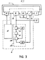
- FIG. 3 another embodiment of a part of the device in FIG. 2 has been shown.
- This other embodiment essentially relates to the control of the adjustable phase shifter 15.
- the same references designate the same elements in this figure and in FIG. 2.
- the adjustable phase shifter 15 is controlled by a switching amplifier circuit 34, connected between the output of the comparator 16 and the phase adjustment integrator 20.
- This arrangement allows a good interference resistance, by performing phase comparison at levels of tension even lower than before.
- the switching circuit 34 makes it possible, after a low-level comparison, to cut the output signal of the comparator 16 so as to be able to amplify it alternately and thus to carry out much finer phase corrections.
- the circuit 34 comprises a cutting member 35, constituted in a known manner, which makes it possible to cut the output signal 18 of the comparator 11, at the frequency of a signal supplied by a cutting oscillator 36.
- the cut signal output of the the member 35 is then amplified by an AC amplifier 37, then detected by a detector 38, synchronized by the oscillator 36.
- the phase shift control integrator 20 therefore receives an amplified signal which improves the sensitivity of the phase shifter control adjustable 15.
- the main advantage of this arrangement is that it is possible to compare phases at a very low level; this avoids taking into account parasitic interference on the line, while making it possible to control the adjustment of phases between transmission and reception, with great sensitivity.
- the gain adjustment circuit 21, which is not shown in detail in this figure, is identical to the circuit 21 in FIG. 2.
- the transmitter-receiver assembly 4 comprises a high-frequency pilot oscillator 13, one output of which is connected, to a first input of the phase-shifter circuit 15.
- This transmitter-receiver assembly also includes a mixer 39 of which a first input 40 constitutes the reception input of the assembly transceiver, while a second input 41 is connected to the output 14 of the high frequency oscillator 13.
- a frequency translation circuit 42 with single side band, constituted in known manner, has a first input 43 connected at an output of the adjustable phase shifter 15.
- a second input 44 of this frequency translation circuit is connected to the output of a low-frequency oscillator 45; the output 46 of the frequency translation circuit 42 constitutes the emission output of the transmitter-receiver assembly.
- This assembly also includes a phase comparator 47, a first input 48 of which is connected to the output of the mixer 39 by means of a low-frequency amplifier circuit 50, with a narrow band.
- a second phase comparator input 49 is connected to the output of the low frequency oscillator 45; finally, the output of this phase comparator is connected to an input 19 for controlling the adjustment phase shifter 15, by means of a phase adjustment integrator 20; this output of the phase comparator 47 also controls the triggering of the alarm 12.
- the low-frequency, narrow-band amplifier circuit 50 includes a band-pass filter 51, the central frequency of which corresponds to the frequency of the low-frequency oscillations delivered by the oscillator 45.
- the input 52 of this filter is connected to the output of the mixer 39, while the output 53 of this filter is connected to the input of a clipping amplifier 54; the output 55 of this amplifier is connected to the first input 48 of the comparator 47.
- a low-pass filter 56 is connected between the second end 9 of the line 1, and the input of the attenuator 10. This other embodiment of the device of the invention ensures a very high immunity to any external interference. This result is obtained thanks to the narrow band filtering of the filter 51.
- the frequency translation circuit 42 makes it possible to add to the high frequency oscillations delivered by the oscillator 15, low frequency oscillations, (1 KHz per example) whose bandwidth is located laterally with respect to the central frequency of the oscillations delivered by the oscillator 15. This frequency translation is carried out at a very low level, taking account of course of the input noise of the device, so as to benefit from the best possible linearity in the frequency response of the device. If Fo denotes the frequency of the oscillations delivered by the high frequency oscillator 15 and F the frequency of the oscillations delivered by the low frequency oscillator 45, these are frequency oscillations Fo + F which are obtained at the output of the translation circuit of frequency 42; these oscillations are sent to input 6 of line 1 via the power amplifier 7.
- the signal is attenuated by the attenuator 10 then mixed with the high frequency reference oscillations Fo, in order to extract the low frequency oscillations F.
- These low frequency oscillations obtained at the output of the mixer 39, are filtered in the narrow band filter 51 , then amplified at constant level by the clipping amplifier 54; this amplifier can be an amplifier with automatic gain control.
- the phase comparison is then performed by the comparator 47, only on the low frequency oscillations received from line 1 and the reference low frequency oscillations, received from the oscillator 45.
- the output of the comparator 47 commands alarm 12 as soon as a voltage threshold is exceeded; this output also controls the adjustment of the adjustable phase shifter 15, via the integrator 20.
- the phase comparator 47 delivers an analog signal whose voltage is proportional to the phase shift between oscillations received on its inputs.
- the phase comparison is carried out on low frequency, low level oscillations, and the device thus produced is much less sensitive to external interference, which is generally high frequency interference.
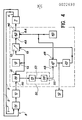
- FIG. 5 there is shown schematically another embodiment of the device shown in Figures 2 and 3, in which some elements have been duplicated.
- the high frequency oscillator 13, the adjustable phase 15 and the power amplifier 7 are common to the two conductors 2 and 3 of line 1; all the other elements of the device are duplicated so as to correspond respectively to each of the conductors, with the exception of the phase adjustment integrators on each conductor; these integrators are replaced here by an adder 56 whose inputs are respectively connected to the outputs of the phase comparators 16A, 16 B , located on each of the conductors 2, 3 and which receive separately, in this embodiment, the oscillations emitted by the high frequency oscillator 13.
- Attenuators 10A, 10 B which may optionally be, as in the embodiment of figures 2 and 3, adjustable gain linear amplifiers through the adjustment circuit gain 21A, 21B, respectively connected at the output of the phase comparators 16A, 16B.
- a subtractor 57 replaces the integrator for adjusting the phase and is connected to the phase comparators outputs 16A, 16 B of each conductor via gain control circuits 21A, 21B. The output of this circuit makes it possible to trigger the alarm 12.
- the attenuators 10A, 10 E , the comparators 16A, 16 B , the gain adjustment circuits 21A, 21 B are respectively identical to the comparators 16, at the attenuator 10, to the gain adjustment circuits 21 of FIGS. 2 and 3.
- phase adjustment integrator with a very large time constant, which is introduced into the phase control loop. This large time constant allows detection of slowly moving intruders.
- the two lines have equal lengths, are spaced apart by a distance d and are situated for example parallel to the ground. They are excited in phase so that the electromagnetic field closes by the ground.
- the two identical reception chains take into account the signals coming from the two conductors.
- Each chain separately measures the phase in relation to the reference phase; then, using the adder 56 and the subtractor 57, the sum and the difference of the phase differences between the phase of the oscillations received from each conductor and the phase of the reference oscillations are made; this sum available in the form of an analog signal at the output of the adder 56, makes it possible to control the adjustable phase shifter 15 so that the device follow the variations common to the two lines; these variations may be due, for example, to bad weather.
- the difference available in the form of an analog signal at the output of the subtractor 57, makes it possible to trigger the alarm 12, as soon as a predetermined threshold is exceeded, at the output of the subtractor. Indeed, in this case, an intrusion cannot cause simultaneously the same disturbances on the two conductors of the line whose distance d can be two to three meters for example.
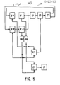
- FIG. 6 there is shown another embodiment of the device of the invention, corresponding to the embodiment of the device shown in Figure 4, but in which certain elements have been duplicated.
- the high frequency oscillator 13, the low frequency oscillator 45, the adjustable phase shifter 15, the frequency translation circuit 42, the power amplifier 7, are common to the two conductors 2, 3 of line 1; the other elements of the device described in FIG. 4 are duplicated in this other embodiment.
- the conductors on the side of the second end of the line, are respectively connected to filters 56A, 56 B , the outputs of which are connected to the inputs of the attenuators 10A, 10 B ; mixers 39A, 39 B respectively receive the signals coming from the attenuators 10A, 10 B and from the high frequency oscillator 13.
- the outputs of these mixers are respectively connected to filters narrow band 51A, 51B, the outputs of which are connected to the clipping amplifiers 54A, 54 B.
- the outputs of amplifiers 54A, 548 are connected to the inputs of phase comparators 47A, 47B, which make it possible to compare the phases of the low frequency oscillations coming from each conductor of the line, after filtering, with the phase of the low frequency oscillations of l oscillator 45.
- the outputs of these comparators are respectively connected to the inputs of adder 56 and subtractor 57; the output of this subtractor controls the alarm 12. As in the embodiment of FIG.
- the sum of the signals coming from the phase comparators 47A, 47B, makes it possible to control the phase adjustment of the adjustable phase shifter 15; this command makes it possible to follow the variations in the transfer functions of the two conductors of line 1; these variations may be due to bad weather; the phase difference of the signals from the comparators 47A, 47B, makes it possible to trigger the alarm 12, as soon as a predetermined voltage threshold is exceeded at the output of the subtractor 57.
- a predetermined voltage threshold is exceeded at the output of the subtractor 57.
Landscapes
- Physics & Mathematics (AREA)
- General Physics & Mathematics (AREA)
- Electromagnetism (AREA)
- Burglar Alarm Systems (AREA)
Applications Claiming Priority (2)
| Application Number | Priority Date | Filing Date | Title |
|---|---|---|---|
| FR7918318 | 1979-07-16 | ||
| FR7918318A FR2461990A1 (fr) | 1979-07-16 | 1979-07-16 | Dispositif electronique de detection d'intrusions dans un environnement |
Publications (1)
| Publication Number | Publication Date |
|---|---|
| EP0022693A1 true EP0022693A1 (fr) | 1981-01-21 |
Family
ID=9227896
Family Applications (1)
| Application Number | Title | Priority Date | Filing Date |
|---|---|---|---|
| EP80400935A Withdrawn EP0022693A1 (fr) | 1979-07-16 | 1980-06-24 | Dispositif électronique de détection d'intrusions dans un environnement |
Country Status (3)
| Country | Link |
|---|---|
| EP (1) | EP0022693A1 (show.php) |
| ES (1) | ES493383A0 (show.php) |
| FR (1) | FR2461990A1 (show.php) |
Cited By (1)
| Publication number | Priority date | Publication date | Assignee | Title |
|---|---|---|---|---|
| FR2609823A1 (fr) * | 1987-01-16 | 1988-07-22 | Pagnol Frederic | Procede et dispositif pour la detection de l'approche d'un objet par un corps etranger |
Families Citing this family (1)
| Publication number | Priority date | Publication date | Assignee | Title |
|---|---|---|---|---|
| FR2679043B1 (fr) * | 1991-07-08 | 1993-11-26 | Bertin Et Cie | Detecteur de proximite. |
Citations (1)
| Publication number | Priority date | Publication date | Assignee | Title |
|---|---|---|---|---|
| FR2357014A1 (fr) * | 1976-06-30 | 1978-01-27 | Snecma | Dispositif electronique a ligne d'onde pour la detection d'intrusions dans un environnement |
-
1979
- 1979-07-16 FR FR7918318A patent/FR2461990A1/fr active Granted
-
1980
- 1980-06-24 EP EP80400935A patent/EP0022693A1/fr not_active Withdrawn
- 1980-07-15 ES ES493383A patent/ES493383A0/es active Granted
Patent Citations (1)
| Publication number | Priority date | Publication date | Assignee | Title |
|---|---|---|---|---|
| FR2357014A1 (fr) * | 1976-06-30 | 1978-01-27 | Snecma | Dispositif electronique a ligne d'onde pour la detection d'intrusions dans un environnement |
Cited By (1)
| Publication number | Priority date | Publication date | Assignee | Title |
|---|---|---|---|---|
| FR2609823A1 (fr) * | 1987-01-16 | 1988-07-22 | Pagnol Frederic | Procede et dispositif pour la detection de l'approche d'un objet par un corps etranger |
Also Published As
| Publication number | Publication date |
|---|---|
| FR2461990A1 (fr) | 1981-02-06 |
| FR2461990B1 (show.php) | 1983-02-25 |
| ES8105102A1 (es) | 1981-05-16 |
| ES493383A0 (es) | 1981-05-16 |
Similar Documents
| Publication | Publication Date | Title |
|---|---|---|
| FR2502871A1 (fr) | Systeme de commutation et de combinaison de signaux pour un systeme de communication radio | |
| CA2013552C (fr) | Detecteur portatif de decharges partielles dans les cables et/ou installations en reseau sous tension | |
| FR2526979A1 (fr) | Systeme de detection d'intrusion | |
| EP0522949A1 (fr) | Détecteur de proximité | |
| BE1019955A3 (fr) | Systeme de surveillance pour un emetteur-recepteur doppler. | |
| EP0080927B1 (fr) | Récepteur pour sondeur de détection et de mesure de phénomènes relatifs à l'environnement du globe terrestre | |
| FR2485192A1 (fr) | Procede et dispositif pour mesurer la pression de pneumatiques notamment pour aeronefs | |
| FR2525006A1 (fr) | Detecteur d'intrusion | |
| EP0570289B1 (fr) | Dispositif de détection du passage d'un mobile, à répondeur passif | |
| EP0022693A1 (fr) | Dispositif électronique de détection d'intrusions dans un environnement | |
| EP0073162A1 (fr) | Procédé de protection d'un radar contre les brouillages, et radar pour mettre en oeuvre ce procédé | |
| CA2060935C (fr) | Systeme d'evaluation des performances d'un filtre electrique | |
| EP0014110B1 (fr) | Emetteur-récepteur et son utilisation dans un réseau de télécommunications | |
| EP0141715A2 (fr) | Dispositif de précorrection automatique des non-linéarités dans une chaîne d'amplification de puissance, et son application à un émetteur de télévision | |
| WO2003055116A2 (fr) | Procede et dispositif d'inhibition de terminaux radio, radiotelephones et assimiles | |
| EP0794612B1 (fr) | Procédé de fonctionnement d'au moins un récepteur de signaux radioélectrique placé dans le voisinage d'un organe ou appareillage rayonnant | |
| MC1521A1 (fr) | Systeme antivol de surveillance a haute frequence a faisceaux croises | |
| EP0504015A1 (fr) | Récepteur de signaux modulés en fréquence à bande d'accrochage controlée | |
| EP0708543B1 (fr) | Procédé de transmission d'un signal sur au moins deux canaux | |
| EP0889619B1 (fr) | Dispositif de modulation par déplacement de fréquence comportant un boucle de verrouillage de phase | |
| EP0689301A1 (fr) | Système d'antennes d'émission-réception omnidirectionnel à diversité angulaire et de polarisation | |
| RU2447509C1 (ru) | Устройство для обнаружения противотранспортных мин | |
| FR2630238A1 (fr) | Dispositif de surveillance par cable | |
| FR1449710A (fr) | Appareil de fermeture à commande acoustique | |
| FR2586149A1 (fr) | Amplificateur intermediaire destine a etre utilise dans les liaisons bifilaires d'un reseau telephonique automatique et procede de commande de gain de cet amplificateur |
Legal Events
| Date | Code | Title | Description |
|---|---|---|---|
| PUAI | Public reference made under article 153(3) epc to a published international application that has entered the european phase |
Free format text: ORIGINAL CODE: 0009012 |
|
| 17P | Request for examination filed |
Effective date: 19800702 |
|
| AK | Designated contracting states |
Designated state(s): BE CH DE FR GB IT |
|
| RAP1 | Party data changed (applicant data changed or rights of an application transferred) |
Owner name: COMPAGNIE DE SIGNAUX ET D'ENTREPRISES ELECTRIQUES |
|
| STAA | Information on the status of an ep patent application or granted ep patent |
Free format text: STATUS: THE APPLICATION HAS BEEN WITHDRAWN |
|
| 18W | Application withdrawn |
Withdrawal date: 19821030 |
|
| RIN1 | Information on inventor provided before grant (corrected) |
Inventor name: FOURNIER, JACQUES MAURICE ARMAND |