EP0021998A1 - Apparat zum Feststellen des Durchmessers von Brillengläsern - Google Patents
Apparat zum Feststellen des Durchmessers von Brillengläsern Download PDFInfo
- Publication number
- EP0021998A1 EP0021998A1 EP80400903A EP80400903A EP0021998A1 EP 0021998 A1 EP0021998 A1 EP 0021998A1 EP 80400903 A EP80400903 A EP 80400903A EP 80400903 A EP80400903 A EP 80400903A EP 0021998 A1 EP0021998 A1 EP 0021998A1
- Authority
- EP
- European Patent Office
- Prior art keywords
- reference plane
- carriage
- frame
- receiving surface
- plane
- Prior art date
- Legal status (The legal status is an assumption and is not a legal conclusion. Google has not performed a legal analysis and makes no representation as to the accuracy of the status listed.)
- Granted
Links
- 239000011521 glass Substances 0.000 title description 13
- 238000005259 measurement Methods 0.000 claims abstract description 30
- 229920003023 plastic Polymers 0.000 claims description 6
- 210000003128 head Anatomy 0.000 description 4
- 230000000750 progressive effect Effects 0.000 description 4
- 210000001747 pupil Anatomy 0.000 description 4
- 230000001179 pupillary effect Effects 0.000 description 3
- 210000000887 face Anatomy 0.000 description 1
- 239000003550 marker Substances 0.000 description 1
- 239000000463 material Substances 0.000 description 1
- 238000000034 method Methods 0.000 description 1
- 230000003287 optical effect Effects 0.000 description 1
- 230000000284 resting effect Effects 0.000 description 1
- 238000012800 visualization Methods 0.000 description 1
Images
Classifications
-
- G—PHYSICS
- G02—OPTICS
- G02C—SPECTACLES; SUNGLASSES OR GOGGLES INSOFAR AS THEY HAVE THE SAME FEATURES AS SPECTACLES; CONTACT LENSES
- G02C13/00—Assembling; Repairing; Cleaning
- G02C13/003—Measuring during assembly or fitting of spectacles
- G02C13/005—Measuring geometric parameters required to locate ophtalmic lenses in spectacles frames
Definitions
- the present invention relates to an apparatus for determining the diameter of corrective lenses adaptable to a spectacle frame.
- the corrective lenses for glasses produced generally have a circular outline and opticians must then adapt each lens to the shape of frame chosen by their customers.
- the corrective lens whose diameter is as small as possible but which makes it possible to completely fill the circle of the frame chosen, whose shape is generally essentially non-circular, while ensuring optically correct mounting.
- a corrective lens thus depends on the frame chosen and must also take into account factors related to the user, cmm for example the value of the pupillary half-distance, which is variable according to the individuals. It has proven to be particularly difficult to easily determine, in the presence of a user and a fixed spectacle frame, the diameter of a corrective lens of the chosen type, even though the different sizes of existing lenses are not not available to the practitioner to authorize tests of different sizes that may be suitable.
- a measuring device comprising movable elements and a guide frame whose shape is comparable to that of a spectacle frame is fixed to the frame itself and is used on the patient. Elements of the measuring device are movable vertically and horizontally to superimpose a mark on the pupil of the patient and marks in arcs of a circle make it possible to determine the useful glass diameter.
- a system has drawbacks because it is relatively fragile and involves carrying out a number of fairly long operations on the patient himself, which is relatively inconvenient.
- the fixing of the guide frame of the measuring device to the spectacle frame itself is not suitable for frames without a bezel.
- This known measuring device which is suitable for progressive lenses, cannot be used for bifocals or triple focal lengths and involves too long manipulations when it comes to choosing single vision lenses.
- the object of the present invention is precisely to remedy the aforementioned drawbacks and to make it possible to quickly and easily determine the diameter of lenses suitable for a spectacle frame and for an individual while causing a minimum of discomfort for the user.
- the object of the invention is also to propose a measuring device which can be used to determine the diameter of a wide variety of types of different lenses, in particular single-vision, two-vision and progressive lenses.
- an apparatus of the type mentioned at the start which, according to the invention, comprises at least one base provided with a) a symmetrical linear measurement scale, b) guide means parallel to said measurement scale , and c) a base surface, a support support and centering means for maintaining a spectacle frame in a predetermined position in a reference plane parallel to said measurement scale and symmetrically with respect to to a plane perpendicular to said reference plane and passing through the median axis of said symmetrical measurement scale, and further comprising at least one carriage sliding on said guide means in front of said measurement scale and said reference plane, said carriage comprising a first part provided with a flat receiving surface parallel to said measurement scale, making an angle with respect to said reference plane, and adapted to receive removable plates provided with marks and lines appearing at least the outline of one or more types of raw corrective lenses, and a second part equipped with a semi-reflecting mirror placed in the bisector plane of the dihedron determined by said receiving surface and said reference plane.
- the semi-reflecting mirror is inclined by about 45 ° relative on the one hand to the reference plane and on the other hand to the receiving surface.
- the base receiving surface of the spectacle frame is substantially parallel to said receiving surface of the carriage.
- the support for supporting the spectacle frame comprises a frame which is fixed to the base surface and defines said reference plane.
- the centering means for holding the spectacle frame symmetrically with respect to a plane perpendicular to the reference plane and passing through the median axis of the measurement scale comprise an adjustable support movable parallel to the reference plane.
- the removable plates are made of transparent plastic.
- a measuring scale is formed on the receiving surface of the removable plates.
- the measuring scale formed on the receiving surface of the removable plates can be moved in its plane in a direction perpendicular to the direction of movement of the sliding carriage.
- a light source is placed in the sliding carriage, under the plate receiving surface which is itself transparent.
- a light source is arranged in the base and cooperates with a reflective surface to illuminate said reference plane.
- the apparatus according to the invention thus makes it possible to carry out precise measurements in a convenient manner, owing to the fact that the spectacle frame is always placed on a stable support and that the combination of means used ensures total visualization of all the factors to be taken into account when determining the adequate diameter of a type of lens according to a given spectacle frame.
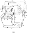
- FIG. 1 shows an apparatus 100 comprising a frame 1 with a front face 11, a base surface 13 intended to receive a spectacle frame 200, and a rear cover 12 whose internal part forms a reflective screen.
- a support frame 15 is mounted on the base surface 13 and makes it possible to retain the frame 200, which rests on the base surface 13, in a plane substantially parallel to the plane of the frame 15.
- a graduated measurement scale 36 is affixed to the front face 11 of the frame 1, below the base plane 13.
- the measurement scale 36 which is parallel both to the base plane 13 and to the reference plane determined by the frame 15 is symmetrical with respect to an origin 360 which determines the axis of the device.
- Centering means 18 are arranged above the base surface 13 and are intended to hold the middle part of the frame 200 on an axis passing through the origin 360 and perpendicular to the measurement scale 36.
- the means of centering 18 may include for example a head 180 which is placed between the two circles 201, 202 of the frame 200, under the connecting bridge 203, so to prevent any play in the lateral direction for the mount 200.
- the centering means 18 are adjustable in height and the position of the head 18Q, mounted on the rod 181, can be controlled by the lever 38, in order to adapt to the different shapes and sizes of frame and fix the axial position of the frame 200 without preventing the two circles 201, 202 of the frame from resting on the base surface 13.
- a lamp 17 (FIG. 2) is advantageously placed in the frame 1 in order to illuminate the internal reflecting surface of the cover 12, and consequently illuminate the reference surface formed by the plane of the frame 200 parallel to the frame 15.
- An opaque cover 19 can be operated using the button 39 to adjust the amount of light sent to the reflective screen of the cover 12. Naturally, the intensity of the light emitted by the lamp 17 can still be adjusted directly by acting on the power supply, using a rheostat for example.
- a carriage 2 is mounted on the front part of the device, in front of the front face 11, the base surface 13 and the mount 200.
- the carriage 2 can slide on a guide 16 parallel to the front face 11 of the frame 1 and at the measurement scale 36.
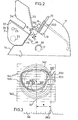
- the carriage 2 comprises a lower body 21 having an upper receiving surface 22, and an upper awning 24 having two lateral branches between which a semi-reflecting mirror 25 is inserted.
- the carriage 2 is open on its faces front and rear at the level of the upper canopy 24 to allow viewing through the reflecting mirror 25, as well as in a central part to reveal the measurement scale 36 in front of which the carriage 2 can travel,
- the mirror 25 is located in the bisector plane of the dihedron formed on the one hand by the reference plane of the frame 15 on which a frame 200 rests and on the other hand, by the receiving surface 22 located on the top of the lower body 21 of the carriage 2.
- the angle between the mirror 25 and the plane of frame reference 15, or the receiving surface 22 is approximately 45 °.
- the receiving surface 22 is preferably constituted by a transparent plate, for example glass or plastic and is intended to receive a removable plate, such as 40 which is also preferably transparent and is made for example of plastic.
- a plate such as 40 comprises a longitudinal axis 41 and various lines 42 representing the contours of standard rough glasses of different diameters.
- the image of the plate 40 is reflected by the semi-transparent mirror 25 and is superimposed on the spectacle frame 200 to form, for an observer placed in front of the mirror 25, virtual lines 141, 142 identical to lines 41, 42.
- a lamp 23 disposed inside the lower body 21 can illuminate a plate 40 and facilitate observation through the semi mirror -transparent 25 which on the one hand returns to the observer the image of the plate 40 and on the other hand reveals the frame 200.
- the balance between the lighting of the frame and of the plate 40 is easily achieved at using the operating button 39 acting on the lamp 17.
- the receiving surface 22 of the carriage body 21 is advantageously itself provided with lines 44 forming a measurement scale, which are superimposed on the lines or marks formed on the plates 40.
- the lines 44 superimposed on the surface receiver 22 can be moved in the plane of said surface, using adjustment knob 26, in particular in a direction perpendicular to the direction of movement of the sliding carriage. This increases the convenience of the measurements.
- the lower part 14 of the apparatus 100 can serve as a storage drawer for the plates 40 which are not used.
- the apparatus according to the invention makes it possible to make this determination with the frame chosen, without additional test or measurement operations having to be carried out on the user, or on the frame worn by the user.
- the frame chosen is first placed on the head 180 of the centering means 18 and leaned against the frame 15 parallel to the latter.
- the frame is then lowered on the base surface 13 until the two circles 201, 201 rest well on the surface 13.
- the frame is thus perfectly centered relative to the axis passing through the origin 360 of the fixed measurement scale 36.
- a plate 40 is then placed on the receiving surface 22 of the carriage 2 carrying lines and marks corresponding to the type of lens which must be installed on the spectacle frame.
- Each plate 40 is rectangular and planar and comprises, in addition to a longitudinal axis 41, a reference 46 corresponding to the optical center and various circles 42 corresponding to standard glass diameters, for example 50, 60, 65, 70, 75 mm. Each plate 40 further carries, inside the circles, marks which depend on the type of glass.
- These additional references 43, 45, 47 do not exist in the case of single-vision lenses, but are necessary in the case of multifocal or progressive lenses and make it possible to correctly position a circle corresponding to a fictitious lens, relative to the spectacle frame. , taking into account the positions previously identified by the pupil of the user with respect to this frame.
- a diameter of the bifocal lens to be mounted on the right circle 201 of a spectacle frame 200 (FIG. 3).
- a plate 40 corresponding to the bifocal glasses is then placed on the receiving surface 22 of the carriage 2.
- the spectacle frame is arranged, as indicated above, against the frame 15, and its central bridge 203 rests on the centering head 180 which is lowered until the lower parts of the circles of the frame rest firmly on the surface 13.
- the carriage 2 is then moved in front of the graduated scale 36 of the front face 11 of the device.
- the measurement scale 36 is visible below the semi-transparent mirror 25 and, preferably, appears through the carriage 2 immediately above the receiving surface 22 of the lower body 21.
- the carriage can then be positioned easily so that, on the measurement scale 36, the distance between the origin 36Q and the reference point situated opposite the longitudinal axis 41 of the plate 40, corresponds to the pupillary half-distance e of the user.
- the relative positions of the frame and the plate 40 are then well defined in the lateral direction and the actual images and virtual circle 201 and plate 40 are superimposed behind the screen formed by the mirror 25.
- the only operation remaining to be performed is to compare the frame circle 201 and the circles 142 representative of lenses for determining the circle with the smallest diameter enabling the entire surface of the frame circle 201 to be covered.
- the height positioning of the lenses is not indifferent.
- the measurement operations carried out on a right-hand circle 201 of the frame can be carried out in the same way on the left-hand circle 202. It suffices to move the carriage 2 to the other side of the central marker 360 and to install on the receiving surface 22 a plate 40 corresponding to left glasses, in the case where the type of glass whose diameter is to be determined is not unifocal.
- the apparatus according to the invention can be used to determine the diameter of very different types of glasses, without having these glasses beforehand, but simply inexpensive plates, for example, in plastic material easy to make, since it suffices that they bear a limited number of marks characteristic of the type of glass to be chosen.
- the manipulations aimed at superimposing the image 140 of a plate 40 on a frame 200 are particularly simple since, as soon as the frame is placed on the device, it suffices to move in two perpendicular directions, by simple sliding along guides 16 and 27 respectively the carriage 2 with respect to the base 1 of the device and the plate 40 with respect to the carriage 2.
- the semi-transparent mirror 25 be situated substantially in a vertical plane, or slightly inclined relative to the vertical, and that the base surface 13 as well as the receiving surface 22 are inclined by so that their front part is raised and that a spectacle frame 200 and a plate 40 can easily come into abutment respectively against the support frame 1 5 and against the bottom of the carriage 2 or the front face 11 of the base 1.
Landscapes
- Physics & Mathematics (AREA)
- Geometry (AREA)
- Health & Medical Sciences (AREA)
- General Physics & Mathematics (AREA)
- Ophthalmology & Optometry (AREA)
- Optics & Photonics (AREA)
- Eyeglasses (AREA)
- Testing Of Optical Devices Or Fibers (AREA)
Applications Claiming Priority (2)
| Application Number | Priority Date | Filing Date | Title |
|---|---|---|---|
| FR7915702A FR2459494A1 (fr) | 1979-06-19 | 1979-06-19 | Appareil pour la determination du diametre de verres correcteurs de lunettes |
| FR7915702 | 1979-09-19 |
Publications (2)
| Publication Number | Publication Date |
|---|---|
| EP0021998A1 true EP0021998A1 (de) | 1981-01-07 |
| EP0021998B1 EP0021998B1 (de) | 1984-05-30 |
Family
ID=9226803
Family Applications (1)
| Application Number | Title | Priority Date | Filing Date |
|---|---|---|---|
| EP80400903A Expired EP0021998B1 (de) | 1979-06-19 | 1980-06-19 | Apparat zum Feststellen des Durchmessers von Brillengläsern |
Country Status (4)
| Country | Link |
|---|---|
| US (1) | US4309826A (de) |
| EP (1) | EP0021998B1 (de) |
| DE (1) | DE3068015D1 (de) |
| FR (1) | FR2459494A1 (de) |
Cited By (5)
| Publication number | Priority date | Publication date | Assignee | Title |
|---|---|---|---|---|
| EP0185997A1 (de) * | 1984-12-22 | 1986-07-02 | Reinhard Wehmeier | Demonstrationsgerät zur Veranschaulichung der erforderlichen Glasgrössen für Brillen |
| US4625418A (en) * | 1985-03-08 | 1986-12-02 | Essilor International Cie Generale D'optique | Apparatus for determining the diameter of a lens to fit an eyeglass frame |
| US4817024A (en) * | 1984-03-02 | 1989-03-28 | Hoya Corporation | Spectacle-frame shape data producing method |
| FR2659436A1 (fr) * | 1990-03-09 | 1991-09-13 | Nikon Corp | Dispositif de mesure de la configuration d'un verre de lunette, et appareil le comportant. |
| EP0560467A3 (en) * | 1992-03-13 | 1994-06-22 | Andreas Heinz Christ Scheibner | Measure board with radiusadapter for frame-slap-shapes on a measurescale witch is fixed between two transparent plastic sheets |
Families Citing this family (1)
| Publication number | Priority date | Publication date | Assignee | Title |
|---|---|---|---|---|
| JPS5955411A (ja) * | 1982-09-24 | 1984-03-30 | Hoya Corp | 眼鏡レンズの最適肉厚決定方法 |
Citations (4)
| Publication number | Priority date | Publication date | Assignee | Title |
|---|---|---|---|---|
| FR1491018A (fr) * | 1966-08-31 | 1967-08-04 | Perfectionnements apportés aux dispositifs universels de précision à copie directe pour reproduire le contour du verre corrigé selon les données optiques à partir de la monture de lunettes | |
| FR1604128A (de) * | 1967-05-10 | 1971-07-12 | ||
| US3804528A (en) * | 1972-06-05 | 1974-04-16 | Gemco Mfg Co | Print projector for fitting contact lenses |
| US4099881A (en) * | 1975-09-19 | 1978-07-11 | Transidyne General Corporation | Viewer for biological diffusion plate |
Family Cites Families (7)
| Publication number | Priority date | Publication date | Assignee | Title |
|---|---|---|---|---|
| AT232293B (de) * | 1962-07-25 | 1964-03-10 | Oskar Vogel | Pupillenmaß-Einstellgerät |
| FR1493482A (fr) * | 1966-05-14 | 1967-09-01 | Lunetiers Cottet Poichet Soc D | Dispositif pour la mise en place de verres de lunettes sur la machine à meuler en fonction de l'écartement pupillaire du porteur et de l'entr'axe des arcatures de la monture |
| FR1604198A (de) * | 1968-12-30 | 1971-07-26 | ||
| FR2037340A5 (de) * | 1970-02-02 | 1970-12-31 | Netter Roger | |
| FR2362418A1 (fr) * | 1976-08-20 | 1978-03-17 | Essilor Int | Dispositif de mesure et de verification pour le montage des lentilles ophtalmiques |
| US4098002A (en) * | 1977-06-13 | 1978-07-04 | Humphrey Instruments Incorporated | Apparatus for locating inter-pupilary of nose bridge mounted spectacles to lens meter |
| US4196978A (en) * | 1977-10-19 | 1980-04-08 | Johnson D Olin | Biofocal type ophthalmic lens alignment determining device |
-
1979
- 1979-06-19 FR FR7915702A patent/FR2459494A1/fr active Granted
-
1980
- 1980-06-16 US US06/159,619 patent/US4309826A/en not_active Expired - Lifetime
- 1980-06-19 DE DE8080400903T patent/DE3068015D1/de not_active Expired
- 1980-06-19 EP EP80400903A patent/EP0021998B1/de not_active Expired
Patent Citations (4)
| Publication number | Priority date | Publication date | Assignee | Title |
|---|---|---|---|---|
| FR1491018A (fr) * | 1966-08-31 | 1967-08-04 | Perfectionnements apportés aux dispositifs universels de précision à copie directe pour reproduire le contour du verre corrigé selon les données optiques à partir de la monture de lunettes | |
| FR1604128A (de) * | 1967-05-10 | 1971-07-12 | ||
| US3804528A (en) * | 1972-06-05 | 1974-04-16 | Gemco Mfg Co | Print projector for fitting contact lenses |
| US4099881A (en) * | 1975-09-19 | 1978-07-11 | Transidyne General Corporation | Viewer for biological diffusion plate |
Cited By (5)
| Publication number | Priority date | Publication date | Assignee | Title |
|---|---|---|---|---|
| US4817024A (en) * | 1984-03-02 | 1989-03-28 | Hoya Corporation | Spectacle-frame shape data producing method |
| EP0185997A1 (de) * | 1984-12-22 | 1986-07-02 | Reinhard Wehmeier | Demonstrationsgerät zur Veranschaulichung der erforderlichen Glasgrössen für Brillen |
| US4625418A (en) * | 1985-03-08 | 1986-12-02 | Essilor International Cie Generale D'optique | Apparatus for determining the diameter of a lens to fit an eyeglass frame |
| FR2659436A1 (fr) * | 1990-03-09 | 1991-09-13 | Nikon Corp | Dispositif de mesure de la configuration d'un verre de lunette, et appareil le comportant. |
| EP0560467A3 (en) * | 1992-03-13 | 1994-06-22 | Andreas Heinz Christ Scheibner | Measure board with radiusadapter for frame-slap-shapes on a measurescale witch is fixed between two transparent plastic sheets |
Also Published As
| Publication number | Publication date |
|---|---|
| EP0021998B1 (de) | 1984-05-30 |
| US4309826A (en) | 1982-01-12 |
| FR2459494B1 (de) | 1983-03-18 |
| DE3068015D1 (en) | 1984-07-05 |
| FR2459494A1 (fr) | 1981-01-09 |
Similar Documents
| Publication | Publication Date | Title |
|---|---|---|
| CA2811410C (fr) | Methode de selection de lentilles ophtalmiques progressives | |
| FR2915289A1 (fr) | Dispositif et procede de preparation d'une lentille ophtalmique en vue de son usinage | |
| EP3082567B1 (de) | Vorrichtung und verfahren zur messung von subjektiver refraktion | |
| EP1817562B1 (de) | Einrichtung zum automatischen messen von kenngrössen einer brillenlinse | |
| EP1825243B1 (de) | Verfahren und einrichtung zur messung der stärke einer brillenlinse durch globale kontaktfreie optische messung und verfolgung | |
| EP1827756A1 (de) | Vorrichtung zur automatischen befestigungsvorbereitung für ophthalmische linsen, die die gleichzeitige behandlung mehrerer linsen ermöglicht | |
| EP2091689B1 (de) | Vorrichtung zur bestimmung der position und/oder der querabmessung eines bohrlochs in einer linse zur herstellung von brillen mit randlosem rahmen | |
| EP2851739B1 (de) | Verfahren zur Erfassung und Messung von geometrischen Daten eines Demonstrationsglases, das an ein Brillengestell angepasst ist | |
| WO2005092570A1 (fr) | Methode de centrage manuel d'une lentille ophtalmique dans un centreur-bloqueur et dispositif centreur-bloqueur associe | |
| EP0021998B1 (de) | Apparat zum Feststellen des Durchmessers von Brillengläsern | |
| FR2663528A3 (fr) | Procede pour la prise des mesures necessaires au montage des verres correcteurs et moyens pour sa mise en óoeuvre. | |
| EP2196845B1 (de) | Verfahren zur Vorbereitung einer ophthalmischen Linse zwecks ihres Einbaus in eine gewölbte Brillenfassung | |
| FR3013620A1 (fr) | Procede de biseautage d'une lentille ophtalmique | |
| FR2931002A1 (fr) | Ensemble de mesure de parametres ophtalmiques | |
| FR3022641A1 (fr) | Appareil centreur-bloqueur pour lentille ophtalmique | |
| CA2692840A1 (fr) | Procede et dispositif de mesure du galbe d'une monture de lunettes | |
| FR2474177A1 (fr) | Procede et dispositif de positionnement relatif d'un appareil de mesure optique et d'une monture de lunettes | |
| FR2829842A1 (fr) | Dispositif d'acquisition des parametres de positionnement de verres ophtalmiques sur une monture de lunettes | |
| FR2690833A1 (fr) | Mensurateur à prise de vue pour l'adaptation de lunettes à un patient. | |
| FR2763707A1 (fr) | Centrale de mesure en optique | |
| FR2878978A1 (fr) | Methode de blocage d'une lentille ophtalmique en vue de son detourage et dispositif de preparation automatique au montage d'une lentille ophtalmique | |
| EP0547965B1 (de) | Zentriergerät für Augen-Korrekturgläser | |
| FR2971929A1 (fr) | Methode et dispositif de mesure des parametres necessaires a la fabrication de lunettes a la morphologie d'un individu donne | |
| FR2668358A1 (fr) | Procede et dispositif pour le centrage de verres correcteurs sur une monture de lunette. |
Legal Events
| Date | Code | Title | Description |
|---|---|---|---|
| PUAI | Public reference made under article 153(3) epc to a published international application that has entered the european phase |
Free format text: ORIGINAL CODE: 0009012 |
|
| AK | Designated contracting states |
Designated state(s): DE GB IT NL |
|
| 17P | Request for examination filed |
Effective date: 19810703 |
|
| ITF | It: translation for a ep patent filed | ||
| GRAA | (expected) grant |
Free format text: ORIGINAL CODE: 0009210 |
|
| AK | Designated contracting states |
Designated state(s): DE GB IT NL |
|
| PG25 | Lapsed in a contracting state [announced via postgrant information from national office to epo] |
Ref country code: NL Effective date: 19840530 |
|
| REF | Corresponds to: |
Ref document number: 3068015 Country of ref document: DE Date of ref document: 19840705 |
|
| PGFP | Annual fee paid to national office [announced via postgrant information from national office to epo] |
Ref country code: DE Payment date: 19840712 Year of fee payment: 5 |
|
| NLV1 | Nl: lapsed or annulled due to failure to fulfill the requirements of art. 29p and 29m of the patents act | ||
| PLBE | No opposition filed within time limit |
Free format text: ORIGINAL CODE: 0009261 |
|
| STAA | Information on the status of an ep patent application or granted ep patent |
Free format text: STATUS: NO OPPOSITION FILED WITHIN TIME LIMIT |
|
| 26N | No opposition filed | ||
| PG25 | Lapsed in a contracting state [announced via postgrant information from national office to epo] |
Ref country code: GB Effective date: 19880619 |
|
| GBPC | Gb: european patent ceased through non-payment of renewal fee | ||
| PG25 | Lapsed in a contracting state [announced via postgrant information from national office to epo] |
Ref country code: DE Effective date: 19890301 |