EP0021983A1 - Verfahren und Apparat zur Beschleunigung eines Festkörpers - Google Patents
Verfahren und Apparat zur Beschleunigung eines Festkörpers Download PDFInfo
- Publication number
- EP0021983A1 EP0021983A1 EP80400885A EP80400885A EP0021983A1 EP 0021983 A1 EP0021983 A1 EP 0021983A1 EP 80400885 A EP80400885 A EP 80400885A EP 80400885 A EP80400885 A EP 80400885A EP 0021983 A1 EP0021983 A1 EP 0021983A1
- Authority
- EP
- European Patent Office
- Prior art keywords
- projectile
- plasma
- region
- path
- along
- Prior art date
- Legal status (The legal status is an assumption and is not a legal conclusion. Google has not performed a legal analysis and makes no representation as to the accuracy of the status listed.)
- Withdrawn
Links
Images
Classifications
-
- H—ELECTRICITY
- H05—ELECTRIC TECHNIQUES NOT OTHERWISE PROVIDED FOR
- H05H—PLASMA TECHNIQUE; PRODUCTION OF ACCELERATED ELECTRICALLY-CHARGED PARTICLES OR OF NEUTRONS; PRODUCTION OR ACCELERATION OF NEUTRAL MOLECULAR OR ATOMIC BEAMS
- H05H1/00—Generating plasma; Handling plasma
- H05H1/54—Plasma accelerators
-
- F—MECHANICAL ENGINEERING; LIGHTING; HEATING; WEAPONS; BLASTING
- F41—WEAPONS
- F41B—WEAPONS FOR PROJECTING MISSILES WITHOUT USE OF EXPLOSIVE OR COMBUSTIBLE PROPELLANT CHARGE; WEAPONS NOT OTHERWISE PROVIDED FOR
- F41B6/00—Electromagnetic launchers ; Plasma-actuated launchers
-
- H—ELECTRICITY
- H05—ELECTRIC TECHNIQUES NOT OTHERWISE PROVIDED FOR
- H05H—PLASMA TECHNIQUE; PRODUCTION OF ACCELERATED ELECTRICALLY-CHARGED PARTICLES OR OF NEUTRONS; PRODUCTION OR ACCELERATION OF NEUTRAL MOLECULAR OR ATOMIC BEAMS
- H05H1/00—Generating plasma; Handling plasma
- H05H1/02—Arrangements for confining plasma by electric or magnetic fields; Arrangements for heating plasma
- H05H1/04—Arrangements for confining plasma by electric or magnetic fields; Arrangements for heating plasma using magnetic fields substantially generated by the discharge in the plasma
- H05H1/06—Longitudinal pinch devices
-
- Y—GENERAL TAGGING OF NEW TECHNOLOGICAL DEVELOPMENTS; GENERAL TAGGING OF CROSS-SECTIONAL TECHNOLOGIES SPANNING OVER SEVERAL SECTIONS OF THE IPC; TECHNICAL SUBJECTS COVERED BY FORMER USPC CROSS-REFERENCE ART COLLECTIONS [XRACs] AND DIGESTS
- Y02—TECHNOLOGIES OR APPLICATIONS FOR MITIGATION OR ADAPTATION AGAINST CLIMATE CHANGE
- Y02E—REDUCTION OF GREENHOUSE GAS [GHG] EMISSIONS, RELATED TO ENERGY GENERATION, TRANSMISSION OR DISTRIBUTION
- Y02E30/00—Energy generation of nuclear origin
- Y02E30/10—Nuclear fusion reactors
Definitions
- the present invention relates generally to a method of and apparatus for accelerating a solid mass along a predetermined path, and more particularly to such a method and apparatus wherein a plasma discharge is imploded toward the mass, so the plasma arrives on a surface of the mass to impart force components to the mass along and normal to the path.
- an object of the present invention to provide a new and improved method of and apparatus for accelerating a solid mass to very high velocities by electromagnetically derived forces.
- Another object of the invention is to provide a new and improved method of and apparatus for accelerating a solid mass to a very high velocity by the use of electromagnetically derived forces that guide the mass, and avoid the need for constraining rails.
- Another object of the invention is to provide a new and improved method of and apparatus for accelerating a solid mass along a predetermined path wherein force fields resulting from the electromagnetic source do not tend to have a destructive effect on the mass.
- Another object of the present invention is to provide a new and improved electromagnetic method of and apparatus for accelerating a solid mass along a predetermined path at high velocity in such a manner that eddy current overheating of the mass does not occur.
- Still another object of the invention is to provide a new and improved electromagnetic method of and apparatus for accelerating a mass stably along a predetermined path wherein the mass is approximately at room temperature or in some cases lower than room temperature but above cyrogenic temperatures as it enters an accelerating field.
- a solid mass preferably a projectile
- a plasma layer adjacent the projectile surface layer is accelerated along a predetermined path by passing an electric discharge through a plasma layer adjacent the projectile surface layer.
- the discharge plasma is imploded against the projectile surface layer so the plasma arrives on a region of the peripheral surface to impart force components to the mass along and normal to the path, to thereby accelerate the mass along the path.
- the plasma arrives at the region on opposite sides of the surface with substantially equal forces so the normal components are balanced and the mass is accelerated by the axial components.
- the region against which the forces act is a surface of revolution about a longitudinal axis of the mass and the plasma has a circular inner imploding periphery at right angles to the axis when it arrives at the region.
- the interaction region is tapered toward the longitudinal axis in a direction opposite from the direction of acceleration and the plasma implodes toward the path.
- the plasma interacts with the region to ablate material from the region in a direction generally normal to the region to impart a force generally in the direction of the path. It is believed that all of these mechanisms occur to some degree, but that certain of the mechanisms are more dominant than others, depending upon the manner in which the plasma discharge is initiated.
- the mass must interact with the imploding plasma over a relatively long distance, such as below one meter to several hundreds of meters, or even greater distances if higher velocities are desired.
- implosion of the plasma is synchronized with the acceleration of the mass along the path so the arrival of the plasma on the region is matched with movement of the projectile or mass axis along the path.
- the synchronism is obtained by initiating separate plasma discharges at spaced regions along the path. In one embodiment the discharges are timed so that they occur at the spaced regions downstream of the mass prior to the mass arriving at the regions.
- the separate discharges are initiated in response to a position detector for the projectile along the - path. It is to be understood, however, that the separate plasma discharges could be initiated in response to a preprogrammed source that very accurately predicts the position of the projectile along the path. In another embodiment, the discharges occur in response to ionized plasma in an upstream section being swept into the abutting downstream section by the projectile.
- the present invention is able to achieve mass velocities in the range of about 10 5 to 10 7 centimeters per second while avoiding eddy current overheating of the mass because the projectile can be formed as a dielectric.
- the mass can include metal, while avoiding the overheating problem due to eddy currents, by shaping the discharge current pulse applied to the plasma, so the plasma has a relatively weak magnetic field when it arrives at the surface. It appears that limitations of the accelerating force which can be applied to the projectile are concerned with the requirement that the projectile should not undergo excessive damage, such as crushing or spalling, in response to the strong accelerating forces.
- the mass accelerator of the present invention is useful as a device for firing projectiles into space from the surface of the earth at velocities in the range of 1.5 x 10 6 - 4 x 10 6 centimeters per second.
- the device can be carried in space craft in earth orbit to fire projectiles into outer space at lower velocities.
- the device can be used for injecting projectiles of radioactive waste or small probes into outer space.
- the device can be used as a means for rapidly activating electrical switches, by opening or closing them, or as a means for producing transient high pressure or high energy inpact conditions for various material response industrial applications.
- high power, stable mass acceleration is achieved while minimizing the problem of mass or projectile overheating due to eddy currents while also avoiding frictional effects due to contact between the projectile and other solid surfaces, such as guide rails.
- these results are achieved, in part, by using a plurality of cascaded accelerating sections positioned along the length of the path.
- the sections are positioned in an envelope containing a gas and each section includes anode and cathode electrodes which form a discharge module for discharge plasma through the gas.
- Each discharge module provides an imploded current discharge through a gas layer near the projectile surface.
- the anode and cathode electrodes of each module are longitudinally spaced along, but remain remote from, the path.
- a solid dielectric remote from and surrounding the path extends between the electrodes.
- a high voltage source connected to the electrodes causes current to flow from the anode, through plasma situated at a radius outside of the projectile path, to the cathode.
- the self-magnetic field of the discharge which is azimuthal relative to the acceleration direction of the projectile, drives the plasma layer radially inward against the projectile surface, to propel the projectile.
- the electrode arrangement causes maximum pressure and accelerating forces to occur at the projectile in the center of the electrode arrangement, rather than at a support arrangement for the electrodes.
- the projectile has a conical or - other type of tapered peripheral shape, with the taper extending in a direction opposite from the direction of acceleration.
- an axial force component is imparted to the projectile by the imploding radial plasma, to accelerate the projectile along the path.
- the radially directed force components against the projectile from the imploding plasma stabilize the projectile on the path. Stability of the projectile is also enhanced by arranging .the projectile so that the center of mass thereof is behind the average center of action of the force components on the projectile.
- one embodiment of the invention includes a plurality of cascaded discharge modules placed end to end. As the projectile passes through a given module, a high'voltage pulse is switched across the electrodes of a downstream module, to initiate a propelling discharge in the downstream module. The discharge causes the plasma to be radially imploded so that the plasma arrives on the projectile surface as the projectile passes through-the downstream module. This series of driving discharges is maintained by switching on the discharge modules in sequence, and with the correct timing as the projectile advances through the accelerator.
- the projectiles utilized in the present invention ' can be constructed out of various materials, either dielectrics or metals.
- materials either dielectrics or metals.
- Eddy currents in the outer layers of the projectile must be minimized to prevent heating within the projectile, which heating can be so severe as to cause premature melting of the projectile before a high velocity is reached.
- the plasma pressure on the projectile can be derived mainly from the implosion momentum of the discharge so that the driving current can be reduced just before impact with the projectile surface.
- the voltage applied to spaced electrodes along the projectile path is reduced to a relatively low value, or to zero, or is reversed when the plasma had propagated to a region adjacent the projectile surface; such a result'can be achieved with an exponentially damped or over damped voltage source, such as a transmission line connected to a high voltage source.
- eddy current heating can be completely avoided by constructing the projectile of a dielectric, in which case electric current is able to flow only through the surface plasma layer pinched against the projectile.
- the plasma discharge adjacent to the projectile surface can be initiated in several ways.
- the discharge can be initiated in low density background gas between an anode and cathode, adjacent a solid dielectric close to or aligned with tips of the electrodes proximate the projectile.
- low density gas along the surface of a dielectric between the anode and cathode electrodes is ionized by a discharge between the electrodes, adjacent a solid dielectric remote from tips of the electrodes proximate the projectile.
- the ionized discharge is imploded radially inward against the projectile surface in response to the magnetic field induced in the gas as a plasma.
- sufficient gas can be continuously ablated from the projectile surface as the projectile advances between adjacent modules containing anode and cathode electrodes.
- entry of the projectile into a gap between the anode and cathode electrodes of a particular module increases gas pressure between the electrodes.
- the increased pressure reduces the impedance between the module electrodes to enable substantial current to flow between the electrodes so the projectile effectively activates a switch that triggers the discharge.
- a gas puff is injected into the first module to initiate the sequence of discharges in synchronism with movement of the projectile through the modules.
- a plurality of sharpened needle electron emitters can be distributed azimuthally around the inner cathode edge to insure an azimuthally uniform discharge.
- each module can include a light beam which is interrupted as the projectile is suitably positioned in the module between the electrodes, to control activation of pulses in the modules.
- Various projectile shapes can be utilized to assure that a forward accelerating force is applied to it in response to a radially directed imploding plasma discharge.
- the projectile shape is designed so that there is a stable progression of the projectile as it advances between modules of the accelerator.
- the projectile includes a tail section having a relatively small curvature to insure that a pinched discharge is provided with a hard core, so that kink instability, as described on page 4-208 of Handbook of Physics, Second Edition, edited by E. U. Condon et al, 1967, McGraw-Hill Inc., does not occur as a main tapered section having greater curvature advances between electrodes of adjacent modules.
- projectile having'masses ranging from fractions of a gram to kilograms can be accelerated to velocities in the range of approximately 10 5 centimeters per second to 10 7 centimeters per second without melting the whole projectile.
- Maximum propelling force densities occur adjacent the projea-. tile surface and not at the surrounding electrode structures, and stable acceleration is obtained without the use of guide rails because of the balanced forces radially applied to the projectile.
- the invention can be utilized to provide rapid switching in electrical circuits by accelerating a projectile to a velocity in the range of 10 6 centimeters per second to 3 x 10 6 centimeters per second.
- an electrically conducting projectile having a metallic skin, is fired into a gap between a pair of adjacent electrical conductors, having a spacing less than the projectile length.
- the metallic skin of the projectile closes a circuit between the two conductors, or it could rapidly remove a conducting section of a circuit by impact of the projectile with the electrically conducting sections.
- the invention can also be utilized for disposal of radioactive waste or for launching of space probes by accelerating projectiles to velocities in the range of 1.5 x 10 6 to 4 x 10⁶ centimeters per second.
- projectiles would have a mass in the range of 0.1 to 1 kilogram.
- the principles of the invention would be combined ' with atmospheric hole-boring techniques, to enable the projectiles to be fired directly into space from the surface of the earth, or lower velocities could be utilized to fire the projectiles into space from earth orbit.
- the invention can also be utilized to produce extremely high pressure and high energy density transient conditions in materials which are impacted by a projectile. Such high pressure and high density transient conditions in target mass materials can be utilized for various industrial applications.
- an additional object of the present invention to provide a new and improved apparatus for and method of electromagnetically accelerating projectiles to velocities sufficient to enable the projectiles to be launched into space from the surface of the earth or from earth orbit.
- Still another object of the invention is to provide a new and improved apparatus for and method of accelerating a projectile to a velocity range of 10 6 - 5 x 10 6 centimeters per second, to provide rapid switching in electrical circuits.
- a further object of the invention is to provide a new and improved apparatus for and method of producing extremely high pressure and high energy density transient conditions in materials in response to an electromagnetically accelerated projectile.
- Yet another object of the invention is to provide a new and improved projectile that is configured to enable it to be adapted for stable acceleration along a predetermined path in response to electromagnetically derived forces.
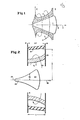
- FIG. 1 of the drawings wherein there is illustrated a tapered projectile 1, formed as a cone symmetrical about Ion-, gitudinal axis 6.
- the peripheral surface of projectile 1 is thus a surface of revolution of a straight line intersecting axis 6 and has a taper toward the axis in a direction opposite from the direction of motion of the projectile, as indicated by arrow 7.
- the surface of revolution is terminated at the .tail of projectile 1, slightly in front of the tail, so that the tail has a smooth, curved configuration that is tangent with the surface of revolution.
- Projectile 1 has a nose that is slightly convex in the direction of arrow 7, relative to the surface of revolution.
- a plasma discharge 2 abuts against the surface of .
- Projectile 1 responds to the force components of plasma discharge 2 so that the projectile is stably accelerated along a path which is coincidemt with the axis 6 and arrow 7.
- Plasma discharge 2 establishes equal but opposite forces on projectile 1 normal to axis 6 because the cross section of the plasma discharge, at right angles to the sheet of Figure 1, is an annulus having its inner periphery in contact with the surface of revolution region of the projectile.
- the longitudinal flow of current 4 through plasma 2 produces an azimuthal magnetic field flux 5 that is coaxial with axis 6 and surrounds the tapered interaction region of projectile 1.
- Azimuthal magnetic field flux 5 implodes plasma 2 inwardly, toward axis 6, so that the configuration of plasma 2 is essentially that of a tapered Z-pinch discharge which is thrust inward against the tapered projectile surface by the magnetic field forces of the plasma. While the current is shown in Figure 1 as flowing through plasma discharge 2 from the tail of projectile 1 to the nose of the projectile, it is to be understood that the current direction could be reversed.
- the force components applied to the interaction region of projectile 1 result from the combined effects of the momentum of the imploded plasma, thermal and magnetic field pressures, together with the reaction forces produced at the interaction region by ablation of projectile material that occurs at the interaction region due to the inward transport of energy via thermal conduction, radiation and Joule dissipation.
- the magnetic field pressure results from an interaction between the azimuthal magnetic field flux 5 and a current produced at the interaction region in response to ionization of gas at the projectile surface by the plasma.
- the net result of these effects is to accelerate projectile 1 forward, to the right in Figure 1 in the direction of arrow 7, and thereby increase the projectile velocity.
- the relative importance of the various effects varies depending upon parameters such as the current initially applied to the plasma, the radius where the plasma is initiated and in what gas density the plasma is initiated.
- the discharge can be initiated in various ways.
- One method for initiating the plasma is to provide a current through a low density background gas between anode and cathode electrodes spaced along the path of projectile 1.
- the discharge can be initiated along the surface of an insulator between the anode and cathode electrodes in a background gas.
- An additional method for initiating the discharge is by ablation of material from the interaction region of projectile 1, so that the discharge moves with the projectile. In the latter case, the projectile can act as a switch to initiate the discharge at successive locations along path 7.
- the basic configuration of the projectile is the same, regardless of the manner in which the discharge is initiated. The different mechanisms are established as a function of the manner in which the plasma discharge is initiated.
- a preferred arrangement for establishing the plasma discharge is to initiate a breakdown voltage in a background gas along the surface of an insulator as an annular plasma region of radius larger than the projectile radius. Such a discharge is imploded inwardly toward path 7 against the interaction region of projectile 1 by magnetic field 5.
- FIG 2 a cross sectional diagram of one embodiment of a Z-pinch diode discharge module.
- a Z-pinch diode discharge module is a basic component of a mass accelerator in accordance with the invention.
- FIG 2 is also illustrated a projectile 22 that is accelerated by and through the Z-pinch diode discharge module.
- the module of Figure 2 includes annular anode and cathode electrodes 17 and 18, which are concentric with axis 24 of projectile 22 which is substantially coincident with path 25 of the projectile. Electrodes 17 and 18 are spaced from each other along path 25 and are mutually insulated.
- Discharge current flows through a relatively low pressure gas, such as air, in the gap between electrodes 17 and 18 in response to the application of a relatively high voltage pulse between the electrodes.
- the current flows from anode 17 to cathode 18; but it is to be understood that the position of the anode and cathode could be reversed, in which case the current would flow in the opposite direction.
- electrodes 17 and 18 are preferably annular discs, with an aperture at the center thereof with sufficient radius to allow passage of projectile 22, it is to ' be understood that the electrodes may be broken up into azimuthal segments around acceleration axis, i.e., path 25, or deformed into a conical or other shapes without altering the basic principles of the invention. In any event, it is necessary for the spacing between electrodes 17 and 18 to be not greater than the length of the projectile passing between the electrodes to assure efficient acceleration of the projectile through the module.
- a high voltage pulse is switched on between the electrodes.
- the high voltage pulse is sufficient to initiate a discharge in a low density gas along the inner surface of dielectric ring 19, which is concentric with path 25.
- Ring 19 is tapered outwardly from axis 25, with the direction of outward taper being in the direction of motion of projectile 22-.
- the high voltage pulse causes a relatively high current, annular discharge 20 to be driven radially inward toward axis 25, away from the interior surface of dielectric ring 19 where it is initiated.
- Plasma 20 accelerates towards path 25 in response to the magnetic field, B, associated with the plasma.
- Magnetic field B is a torroid concentric with path 25 and extends in the azimuthal direction relative to the axis.
- discharge 20 advances radially inward toward path 25, it accumulates more plasma by sweeping up additional background gas by the well known snow plow effect associated with Z-pinching.
- the gas pressure of the background gas, typically air, in region 21 between insulator 19 and path 25 is on the order of one torr but may be any suitable value depending on the desired momentum of pulse at the interaction region of projectile 22.
- the insulator could be a simple, straight cylindrical section separating electrodes 17 and 18.
- the discharge between electrodes 17 and 18 is timed by standard electrical means which sense the position and velocity. of projectile 22 upstream of module 217 so that when projectile 22 arrives at a position where its nose is approximately aligned with cathode 18, the imploding discharge collides with the interaction region of the projectile and propels the projectile forward.
- Projectile 22, as illustrated in Figure 2, has a slightly extended tail section 23.
- Tail section 23 has a curvature less than the curvature of the main portion of projectile 22, adjacent the projectile nose.
- the center of mass of projectile 22 is positioned behind the center of action of the accelerating force on projectile 22, to assist in providing stable acceleration to the projectile.
- the center of mass of projectile 22 could also be established behind the center of action of the accelerating force on the projectile by providing the projectile with a hollow cavity adjacent the nose portion of the projectile.
- Extended tail section 23 has an additional advantage of providing a solid core so that as projectile 22 advances out of the discharge region between electrodes 17 and 18, to the right in Figure 2, the pinched discharge region of plasma against the tapered tail 23 of the projectile is not free to thrash about. Because the pinched discharge region does not thrash about, the well known plasma kink stability phenomena does not occur..The plasma kink stability phenomena is to be avoided because it is likely to produce destabilizing forces on projectile 22. It is to be understood that a number of different projectile shapes could be used without departing from the basic principles of the invention. In the preferred embodiment, wherein a radially directed plasma interacts with the projectile, the projectile is tapered as illustrated.
- the implosion velocity of annular discharge plasma 20 as it approaches the interaction region of projectile 22 must be at least approximately twice as large as the velocity of the projectile along path 25.
- the timing between the discharge and projectile 22 can be arranged so that no contact exists between plasma discharge 20 and any part of projectile 22 prior to arrival of the projectile in the gap between electrodes 17 and 18.
- plasma discharge must be timed to collide with the interaction region of projectile 22 before the projectile has had time to move ahead, outside of the gap of electrodes 17 and 18, i.e., to the right of electrode 18 in Figure 2.
- the implosion time for annular plasma discharge 20 to move radially from insulator surface 19 to the interaction region of projectile 22 can be greater than the transit time of the projectile across the gap between electrodes 17 and 18.
- the implosion time of plasma discharge 20, t imp1 can be larger than the projectile transit time between electrodes 17 and 18, , where L is the gap between electrodes 17 and 18, and U is the velocity of projectile 22 along path 25.
- the implosion time can be calculated as: where r is a radial position from path 25, V r (r) is the inwardly directed radial velocity of annular discharge 20 as a function radial position r, R is the mid point radius of insulator surface 19 from path 25, and r m is the radius of projectile 22 at a distance half way behind the point where the nose of projectile 22 intersects axis 25. If the implosion time is greater than the transit time, a power multiplication can be obtained. The power multiplication occurs because the driving voltage and current applied by electrodes 17 and 18 to the gas accumulate implosion momentum for a longer time than the characteristic projectile encounter time with the plasma ( ).
- the projectile can respond to the accumulated momentum in the plasma only during the encounter time.
- the discharge current in the plasma can be reduced so that when the plasma impacts with projectile 22, eddy current heating of metal parts in the projectile is reduced.
- the gas density in which the discharge is initiated is sufficiently low to enable the final implosion velocity of plasma discharge 20 to exceed the velocity of projectile 22 along path 25.
- the implosion radius of plasma discharge 20 is sufficiently large to provide a discharge momentum at a high surface pressure on impact with the projectile.
- a source of voltage pulses, V (t), (not shown) is connected between electrodes 17 and 18. Initially, the voltage pulse establishes a discharge between electrodes 17 and 18 along the inner edge of dielectric ring 19. As time progresses and the voltage:is maintained across electrodes 17 and 18, the discharge implodes inwardly towards path 25. Current flowing in the discharge causes the azimuthal magnetic B field to be established in and at a greater radius than the discharge. The magnetic B field forces the discharge inwardly. As the discharge propagates toward path 25, it has accumulated gas from the region having a diameter greater than the discharge to increase the mass of gas in the discharge.
- the voltage pulse source can include standard components and can be derived from conventional capacitive or inductive energy storage devices.
- Pulses from the source can be supplied to electrodes 17 and 18 by transmission lines and suitably triggered switches.
- the current, I which flows through the discharge between electrodes 17 and 18 is determined by the circuit equation: where L and R are the total inductance and resistance of the source and circuit connecting the source and electrodes together, as well as the impedance between electrodes 17 and 18.
- Determination of the contribution of discharge 20 to the values of Lp and Rp involves solving hydrodynamic equations for magnetically imploded plasma shells, or alternatively solving equations for simpler dynamic models for such plasma discharges. This is a well studied subject for which there is extensive literature. The literature has been pursued for applications relating to the so-called plasma focus device and to dynamically imploded gas puffs or annular foils which have been imploded in high power diode devices to create impulsive radiation sources.
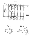
- FIG. 3 is illustrated an embodiment of a mass accelerator including a plurality of discharge modules 51-55 which are axially aligned and concentric with axis 56 which is traversed by projectile 50 so that axis 57 of the projectile is substantially coincident with axis 56.
- Modules 51-55 are located in a partially evacuated envelope 58, which contains a suitable gas.
- envelope 58 contains air at an atmosphere of 1 torr.
- the envelope includes a pressure chamber 59, of well known construction, to provide a transition from the pressure within envelope 58 to ambient, e.g., atmospheric, pressure outside of the envelope.
- a thin metal foil could be positioned at one end of envelope 58 to establish the pressure differential between the interior and exterior of envelope 58; in such an instance, the foil would be easily broken by projectile 50 after it has been accelerated by modules 51-55.
- Each of the cascaded modules within envelope 58 is substantially the same, and is constructed similarly to the module described supra in connection with Figure 2, so the inner diameter of the modules is larger than the maximum diameter of the projectile.
- Adjacent electrodes at adjacent modules are spaced from each other by solid dielectric rings 60 and are connected to each other by large conducting inductors 96 that prevent high current discharge from occuring on the surfaces of the insulators 60 even though the insulator lengths are relatively short in the direction of path 56.
- the value of inductors 96 is selected such that the inductors are virtually open circuits for the entire time while switches 71-75 are closed, typically ten to several hundred microseconds.
- Rings 60 are illustrated as having the same radial thickness as the dielectric rings 79 associated with modules 51-55 for ease of manufacture, but it is to be understood that rings 60 can have any thickness from a minimum at the inner periphery of dielectric envelope 58 to a maximum, which would be from the envelope to about the inner radius of the electrodes.
- the electrodes of modules 51-55 are respectively connected by switches 71-75 to high voltage sources 91-95.
- the voltages of sources 91-95 are typically a few to several tens of kilovolts, depending upon the application of the invention, i.e., the mass of projectile 50 and the desired final speed of the projectile.
- projectile 50 is injected into the first module 51 by a suitable means, such as injection gun 78.
- Injection gun 78 could be a source of chemical explosion to accelerate projectile 50 into module 51 or it could be a relatively low velocity rail gun.
- projectile 50 could be stationary in module 51 and supported by an axial rail that extends along a bore coincident with a portion of projectile axis 57.
- Sensing of the. projectile position can be accomplished by projecting a light beam 76 from source 80 between adjacent modules 51-55 through diametric bores (not shown) in dielectric rings 60. Beam 76 is projected radially toward axis 56 to mirror 81. Mirror 81 is mounted diametrically opposite light source 80 and normally directs light from the source back to a photodetector located within the source. In response to light beam 76 being interrupted, as occurs when the projectile is accelerated along path 56, the photodetector within source 80 derives a signal which is used to determine when to trigger a downstream one of modules 51-55.
- signals from sources 80 are applied to a suitable computer (not shown) which supplies control signals to switches 71-75 to apply high voltage pulses to electrodes of the modules.
- the closure of switches 71-75 is timed so that the discharge of a particular module arrives on the interaction surface or region of projectile 50 when the projectile is appropriately positioned in the anode-cathode gap of the particular module for further accleration.
- the switches are closed in sequence as projectile 50 advances along axis 56 of the accelerator.
- the electrodes of adjacent modules are reversed in electrical polarity so that ionized gas on the surface of projectile 50, resulting from the plasma discharge, experiences alternatingly polarized magnetic fields and discharge currents.
- the alternating polarity is not an essential feature of the invention, although it may have high voltage module packing advantages because it enables the length of insulators 60 to be reduced and/or the size of inductors 96 to be reduced. It is to be understood that various polarity choices for the electrodes of modules 51-55 can be made consistent with the principles of the invention.
- switches 71, 72 and 73 are closed so that discharges are initiated in modules 51, 52 and 53.
- the plasma discharge of module 51 is interacting with the interaction region of projectile 50, to accelerate the projectile along axis 56.
- the plasma of module 52 is farther removed from axis 56 than the plasma in module 51, and the plasma discharge in module 53 is even farther from axis 56.
- the plasma discharges of modules 51-53 are at differing radial positions relative to axis 56 because switches 71-73 are sequentially closed.
- each of the annular modules has a relatively large radius between axis 56 and dielectric ring 79 where the plasma discharge is initiated; for example the inner radius of ring 79 is typically 5 to 50 times the maximum radius of projectile 50.
- the discharge must be initiated several modules downstream of module 51 as projectile 50 moves through module 51.
- FIG 4 is illustrated details of a preferred embodiment of a projectile that could be utilized in connection with the present invention, and which forms a part of the invention.
- the projectile of Figure 4 is a simple conical projectile having a longitudinal axis of symmetry 96 about which a straight line is rotated to form a peripheral surface of revolution.
- the surface of revolution is the region of the projectile against which the forces derived from the plasma are exerted.
- Behind the surface of revolution the projectile includes a curved tail that has a smooth transition between the surface of revolution and the curved portion of the tail. Forward of the surface of revolution, the projectile has a convex nose portion.
- the projectile Immediately behind the projectile nose portion the projectile includes a cavity 61 which causes the projectile to have a center of-massvalong axis 96, at a point relatively far from the projectile nose.
- the center of projectile mass is removed sufficiently far from the nose to be behind the center of action of the propelling forces to provide stable acceleration.
- Projectile 60 could be fabricated from metal, for situations in which the imploded plasma magnetic fields are relatively weak.
- projectile 60 could be fabricated of a dielectric, to avoid eddy current melt down of the projectile for situations, in which the magnetic field of the plasma and currents flowing in the plasma are relatively large.
- projectile 62 has a relatively high curvature proximate the convex nose thereof, and an elongated tail section 64, with a slight curvature. Tail section 64 is terminated by a rounded portion.
- the high and low curvature portions of projectile 62 are both formed as surfaces of revolution and can be the surface of revolution of a hyperbola or exponential function.
- the forward high curvature portion 63 of projectile 62 deflects the imploded plasma rearwardly in a more efficient manner than the relatively straight interaction region of projectile 60.
- the elongated, slightly curved tail section 64 of projectile 62 stabilizes kink instabilities in the pinched discharge plasma at the rear of the projectile.
- Projectile 62 is also provided with a hollow portion 61, proximate its nose.
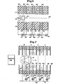
- FIG. 6 of the drawing wherein there is illustrated a further embodiment of the invention wherein projectile 101 is accelerated by the same three forces as the projectile in the embodiment of Figure 3.
- the magnetic pressure and ablation and Joule heating effects on the surface of projectile 101 are greater than the accelerating effects due to the imploding plasma, in contrast to the Figure 3 embodiment.
- the Figure 6 embodiment is not as , advantageous as the Figure 3 embodiment because excessive ablation may cause much of the projectile 101 to disintegrate as it is accelerated.
- the system of Figure 6 does not require any sensing structure to trigger discharges in successive sections, as the gas from section (N-l) triggers the discharge in section N as the projectile advances from section (N-l) to section N.
- the embodiment of Figure 6 includes a series of cascaded sections, three of which (namely sections 102, 103 and 104 which can be respectively considered as sections (N-l), N and (N+l)) are illustrated.
- Each of rings 105 extends between electrodes at opposite ends of each of the sections. Adjacent sections are separated by dielectric rings 120.
- Electrodes 108-114 are metal discs concentric with axis 106 and having the same inner radius as rings 105.
- DC voltages indicated by voltage sources 115-118 are permanently established between adjacent pairs of the electrodes at the boundaries of adjacent sections so that there is an alternation of positive and negative fields established between the electrodes along the length of the accelerator.
- a large inductance 130 is connected between the electrodes of neighboring modules to prevent discharge currents from flowing between the electrodes of neighboring modules.
- the negative and positive electrode sources 115 are respectively connected to cathode and anode 108 and 109
- the positive and negative electrodes of DC source 116 are respectively connected to electrodes 110 and 111
- the negative and positive terminals of DC source 117 are respectively connected to electrodes 110 and 113.
- the ratio between the radii of the inner diameter of the accelerator and of projectile 101, i.e., the radii of rings 105 and electrodes 108-114 is in the range of 1.1 to 3.
- the imploding discharge travels a much smaller radial distance than in the embodiment of Figure 3 and has a much lower velocity when it impacts on the projectile surface than in the Figure 3 embodiment.
- the shorter length and duration of the discharge in the Figure 6 embodiment occurs because the magnetic field acts through a shorter distance and for a shorter time than in the Figure 3 embodiment.
- the region between the acceleration path 106 and the inner edge of rings 105 is evacuated to a low pressure of less than 0.01 torr so that prior to arrival of gas ablated from the projectile, discharge current does not flow in the downstream modules.
- discharge current does not flow in the downstream modules.
- the discharge current start to flow.
- Joule heating of the gases ablated from the tapered surface of projectile .101 As projectile 101 is accelerated between electrodes 108 and 109 it causes a current to flow from electrode 109 to electrode 108 once the projectile is wholly within section 102.
- FIG. 7' of the drawing wherein there is illustrated a modification of the embodiment of the invention illustrated in Figure 3.
- the electrodes are polarized so that there is an alternation of the voltages applied to adjacent electrodes.
- alternate electrodes in the accelerator of Figure 7 are connected to a reference ' potential, such as ground, by bus 122.
- cathode electrodes 123, 125, 127 and 129 are connected to bus 122.
- Anode electrodes 124, 126 and 128 are connected to high voltage terminals of.power supplies 130 through switches 132, 134 and 136, respectively.
- Switches 132, 134 and 136 are connected to terminals of supplies 130 having like polarities, either positive or negative, relative to the reference potential of bus 122.
- Each of switches 132, 134 and 136 is illustrated as being closed and plasma discharges associated therewith are illustrated as being in various stages of propagation toward projectile 121.
- Switches 132, 134 and 136 are closed in response to position sensing devices, similar to those described in connection with Figure 3. In the embodiment of Figure 7, however, closure of one switch results in a plasma discharge being established between two pairs of electrodes, whereby closure of switch 132 results in plasma discharges being established between electrodes 123 and 124 as well as between electrodes 124 and 125.
- there is an additional high voltage power supply 131 having one terminal connected to bus 122 and a second terminal connected to open circuited switch 137.
- Switch 137 is in an open state because projectile 121 has not moved far enough along the accelerator to be sensed by a stage which would cause closure of switch 137. Thereby, no plasma discharge has been initiated between anode 138, connected to switch 137 and cathodes 129, and 139, on either side of and immediately adjacent anode 138.
- logic circuitry (not shown) is responsive to the positional sensors to activate the various switches connected between the high voltage power supplies and the electrodes.
- the logic circuitry responds to the position of the projectile, to calculate the projectile velocity in the accelerator, at each individual module along the accelerator length. In response to the calculated velocity, the time at which the various switches are to be closed is calculated and an actuator is controlled at an appropriate time to provide the switch closure.
- the velocity of the projectile at predetermined positions along the length of the accelerator can be approximated to a relatively accurate extent so that a delay factor is associated with each sensor and a switch which is to be closed in response to the sensor detecting passage of the projectile.
Landscapes
- Physics & Mathematics (AREA)
- Engineering & Computer Science (AREA)
- Plasma & Fusion (AREA)
- Spectroscopy & Molecular Physics (AREA)
- Optics & Photonics (AREA)
- Electromagnetism (AREA)
- General Engineering & Computer Science (AREA)
- Plasma Technology (AREA)
Applications Claiming Priority (2)
| Application Number | Priority Date | Filing Date | Title |
|---|---|---|---|
| US49557 | 1979-06-18 | ||
| US06/049,557 US4429612A (en) | 1979-06-18 | 1979-06-18 | Method and apparatus for accelerating a solid mass |
Publications (1)
| Publication Number | Publication Date |
|---|---|
| EP0021983A1 true EP0021983A1 (de) | 1981-01-07 |
Family
ID=21960455
Family Applications (1)
| Application Number | Title | Priority Date | Filing Date |
|---|---|---|---|
| EP80400885A Withdrawn EP0021983A1 (de) | 1979-06-18 | 1980-06-18 | Verfahren und Apparat zur Beschleunigung eines Festkörpers |
Country Status (3)
| Country | Link |
|---|---|
| US (1) | US4429612A (de) |
| EP (1) | EP0021983A1 (de) |
| JP (2) | JPS57108475A (de) |
Cited By (3)
| Publication number | Priority date | Publication date | Assignee | Title |
|---|---|---|---|---|
| EP0295136A1 (de) * | 1987-06-12 | 1988-12-14 | Gt-Devices | Verfahren und Vorrichtung zur Wasserstoffentwicklung, Vorrichtung zur Projektilbeschleunigung und Verfahren damit |
| EP0346867A3 (de) * | 1988-06-16 | 1990-09-19 | DIEHL GMBH & CO. | Rohrwaffe mit chemisch-elektrischem Hybridantrieb mittels regenerativer Treibmitteleinspritzung |
| FR2650064A1 (fr) * | 1989-07-21 | 1991-01-25 | Diehl Gmbh & Co | Dispositif pour accelerer des projectiles par un plasma chauffe electriquement |
Families Citing this family (22)
| Publication number | Priority date | Publication date | Assignee | Title |
|---|---|---|---|---|
| US4967639A (en) * | 1982-07-15 | 1990-11-06 | Westinghouse Electric Corp. | Rapid burst firing electromagnetic launcher |
| US4555972A (en) * | 1982-12-20 | 1985-12-03 | Westinghouse Electric Corp. | Electromagnetic launcher with powder driven projectile insertion |
| US5033355A (en) * | 1983-03-01 | 1991-07-23 | Gt-Device | Method of and apparatus for deriving a high pressure, high temperature plasma jet with a dielectric capillary |
| US4590842A (en) * | 1983-03-01 | 1986-05-27 | Gt-Devices | Method of and apparatus for accelerating a projectile |
| US4944211A (en) * | 1984-03-19 | 1990-07-31 | Larry Rowan | Mass action driver device |
| US4715261A (en) * | 1984-10-05 | 1987-12-29 | Gt-Devices | Cartridge containing plasma source for accelerating a projectile |
| US4974487A (en) * | 1984-10-05 | 1990-12-04 | Gt-Devices | Plasma propulsion apparatus and method |
| US4640180A (en) * | 1985-06-20 | 1987-02-03 | The United States Of America As Represented By The Secretary Of The Navy | Gun-firing system |
| US4765222A (en) * | 1985-10-28 | 1988-08-23 | The Boeing Company | Electrostatic kinetic energy weapon |
| US5016600A (en) * | 1989-02-01 | 1991-05-21 | International Superconductor Corp. | Methods of generating and controlling a magnetic field without using an external power supply specification |
| US4996903A (en) * | 1989-09-12 | 1991-03-05 | Arakaki Steven Y | Two stage gun |
| US5031503A (en) * | 1989-12-06 | 1991-07-16 | The Boeing Company | Electrostatic projectile accelerator apparatus and related method |
| US6668699B2 (en) * | 1998-08-20 | 2003-12-30 | Ronnie David Russell | Porous nozzle projectile barrel |
| AU2003241502B2 (en) * | 2002-05-28 | 2007-11-01 | Renee Mazaheri | Method and apparatus for moving a mass |
| KR100529299B1 (ko) * | 2003-05-09 | 2005-11-17 | 학교법인 한양학원 | 상압 플라즈마 분사장치 |
| US20040233158A1 (en) * | 2003-05-21 | 2004-11-25 | Stavely Donald J. | Systems and methods for identifying user input |
| US7741577B2 (en) * | 2006-03-28 | 2010-06-22 | Battelle Energy Alliance, Llc | Modular hybrid plasma reactor and related systems and methods |
| WO2009079568A2 (en) * | 2007-12-17 | 2009-06-25 | Johnson Controls Technology Company | Detent spring and end cap structures for a visor vanity |
| US8536481B2 (en) | 2008-01-28 | 2013-09-17 | Battelle Energy Alliance, Llc | Electrode assemblies, plasma apparatuses and systems including electrode assemblies, and methods for generating plasma |
| CA3088556A1 (en) * | 2018-02-20 | 2019-08-29 | Oerlikon Metco (Us) Inc. | Single arc cascaded low pressure coating gun utilizing a neutrode stack as a method of plasma arc control |
| US10962320B1 (en) * | 2019-12-03 | 2021-03-30 | Dorothy Devine Burdine | Light trigger |
| KR102147404B1 (ko) * | 2020-02-19 | 2020-08-24 | 주식회사 영배 | 가스압 또는 공기압을 사용하는 에어 소프트 건 |
Citations (4)
| Publication number | Priority date | Publication date | Assignee | Title |
|---|---|---|---|---|
| US3254564A (en) * | 1963-12-04 | 1966-06-07 | Aerojet General Nucleonics | Magnetic gradient particle accelerator |
| US3295412A (en) * | 1963-12-04 | 1967-01-03 | Aerojet General Co | Magnetic gradient particle accelerator |
| US3335637A (en) * | 1965-12-23 | 1967-08-15 | Fay E Null | Projectile propelled by friction drag of high velocity plasma |
| US3357306A (en) * | 1965-06-29 | 1967-12-12 | Aeroprojects Inc | Accelerating particles to high velocities |
Family Cites Families (14)
| Publication number | Priority date | Publication date | Assignee | Title |
|---|---|---|---|---|
| GB448496A (en) | 1934-12-03 | 1936-06-03 | Nicholas Sandor | Improvements in and connected with the propulsion of projectiles and projectile likeconveyors for goods or passengers |
| FR1033565A (fr) | 1951-01-09 | 1953-07-13 | Procédé de détonation simultanée de toute la surface d'un explosif permettant l'obtention de très hautes températures et de très hautes pressions | |
| US2870675A (en) | 1954-11-15 | 1959-01-27 | Zenith Radio Corp | Acceleration amplifier |
| US2783684A (en) | 1956-03-07 | 1957-03-05 | Gen Electric | Method and means for propagating a mass |
| US2790354A (en) | 1956-03-07 | 1957-04-30 | Gen Electric | Mass accelerator |
| US3148587A (en) | 1962-06-27 | 1964-09-15 | Leonard J Melhart | Magnetohydrodynamic hypervelocity gun |
| US3273553A (en) | 1963-09-12 | 1966-09-20 | Richard H Doyle | Electromagnetically operated gun |
| SE305782B (de) | 1964-01-07 | 1968-11-04 | Crane Packing Ltd | |
| DE1903959U (de) | 1964-07-17 | 1964-11-05 | Agk Ag Fuer Kunststoffprodukte | Verpackung fuer elektroden od. dgl. |
| US3431816A (en) | 1967-07-21 | 1969-03-11 | John R Dale | Mobile gas-operated electrically-actuated projectile firing system |
| GB1413039A (en) | 1972-11-02 | 1975-11-05 | Dainippon Toryo Kk | Falt display system |
| US3854097A (en) | 1973-06-06 | 1974-12-10 | Nasa | Self-energized plasma compressor |
| US3929119A (en) | 1973-06-06 | 1975-12-30 | Nasa | Self-energized plasma compressor |
| US3916761A (en) | 1974-01-29 | 1975-11-04 | Nasa | Two stage light gas-plasma projectile accelerator |
-
1979
- 1979-06-18 US US06/049,557 patent/US4429612A/en not_active Expired - Lifetime
-
1980
- 1980-06-18 EP EP80400885A patent/EP0021983A1/de not_active Withdrawn
- 1980-06-18 JP JP55082664A patent/JPS57108475A/ja active Pending
- 1980-06-18 JP JP55082663A patent/JPS5797083A/ja active Pending
Patent Citations (4)
| Publication number | Priority date | Publication date | Assignee | Title |
|---|---|---|---|---|
| US3254564A (en) * | 1963-12-04 | 1966-06-07 | Aerojet General Nucleonics | Magnetic gradient particle accelerator |
| US3295412A (en) * | 1963-12-04 | 1967-01-03 | Aerojet General Co | Magnetic gradient particle accelerator |
| US3357306A (en) * | 1965-06-29 | 1967-12-12 | Aeroprojects Inc | Accelerating particles to high velocities |
| US3335637A (en) * | 1965-12-23 | 1967-08-15 | Fay E Null | Projectile propelled by friction drag of high velocity plasma |
Non-Patent Citations (1)
| Title |
|---|
| APPLIED OPTICS, Vol. 14, No. 10, October 1975, New York, USA E.B. IGENBERGS et al. "Plasma flow and fast particles in a hypervelocity accelerator: A color presentation", pages 2542-2548. * Page 2542, left-hand column, lines 1-9; page 2546, right-hand column, line 46 to page 2547, right-hand column, line 7; figures 1, 10, 11 * * |
Cited By (3)
| Publication number | Priority date | Publication date | Assignee | Title |
|---|---|---|---|---|
| EP0295136A1 (de) * | 1987-06-12 | 1988-12-14 | Gt-Devices | Verfahren und Vorrichtung zur Wasserstoffentwicklung, Vorrichtung zur Projektilbeschleunigung und Verfahren damit |
| EP0346867A3 (de) * | 1988-06-16 | 1990-09-19 | DIEHL GMBH & CO. | Rohrwaffe mit chemisch-elektrischem Hybridantrieb mittels regenerativer Treibmitteleinspritzung |
| FR2650064A1 (fr) * | 1989-07-21 | 1991-01-25 | Diehl Gmbh & Co | Dispositif pour accelerer des projectiles par un plasma chauffe electriquement |
Also Published As
| Publication number | Publication date |
|---|---|
| US4429612A (en) | 1984-02-07 |
| JPS5797083A (en) | 1982-06-16 |
| JPS57108475A (en) | 1982-07-06 |
Similar Documents
| Publication | Publication Date | Title |
|---|---|---|
| US4429612A (en) | Method and apparatus for accelerating a solid mass | |
| US4590842A (en) | Method of and apparatus for accelerating a projectile | |
| US2783684A (en) | Method and means for propagating a mass | |
| US5033355A (en) | Method of and apparatus for deriving a high pressure, high temperature plasma jet with a dielectric capillary | |
| US3309873A (en) | Plasma accelerator using hall currents | |
| EP0876663B1 (de) | VORRICHTUNG ZUR ERZEUGUNG eines Plasmas | |
| US3864640A (en) | Concentration and guidance of intense relativistic electron beams | |
| US4172008A (en) | Nuclear fusion reactor | |
| US7679025B1 (en) | Dense plasma focus apparatus | |
| US5183956A (en) | Projectile-launching device | |
| US4422013A (en) | MPD Intense beam pulser | |
| US5125321A (en) | Apparatus for and method of operating a cylindrical pulsed induction mass launcher | |
| US3173248A (en) | Ionization and plasma acceleration apparatus | |
| US5339336A (en) | High current ion ring accelerator | |
| US3939816A (en) | Gas filled coaxial accelerator with compression coil | |
| US4458577A (en) | Acceleration apparatus with annular projectile accelerated thereby | |
| US4412967A (en) | Multistage high voltage accelerator for intense charged particle beams | |
| US3029361A (en) | High temperature plasma confinement using a travelling electromagnetic field | |
| US5012720A (en) | Plasma projectile accelerator with valve means for preventing the backward flow of plasma in passage through which projectile is accelerated | |
| US3279175A (en) | Apparatus for generating and accelerating charged particles | |
| US4363774A (en) | Production and utilization of ion cluster acceleration | |
| US4888522A (en) | Electrical method and apparatus for impelling the extruded ejection of high-velocity material jets | |
| Vasilyak et al. | Effect of the rise rate of nanosecond high-voltage pulses on the breakdown of air gaps | |
| US3619812A (en) | Metallic vapor laser | |
| US3265583A (en) | Apparatus for producing and purifying plasma |
Legal Events
| Date | Code | Title | Description |
|---|---|---|---|
| PUAI | Public reference made under article 153(3) epc to a published international application that has entered the european phase |
Free format text: ORIGINAL CODE: 0009012 |
|
| AK | Designated contracting states |
Designated state(s): DE FR GB |
|
| 17P | Request for examination filed |
Effective date: 19810722 |
|
| RAP1 | Party data changed (applicant data changed or rights of an application transferred) |
Owner name: GT - DEVICES |
|
| RAP1 | Party data changed (applicant data changed or rights of an application transferred) |
Owner name: GT - DEVICES |
|
| STAA | Information on the status of an ep patent application or granted ep patent |
Free format text: STATUS: THE APPLICATION IS DEEMED TO BE WITHDRAWN |
|
| 18D | Application deemed to be withdrawn |
Effective date: 19850930 |
|
| RIN1 | Information on inventor provided before grant (corrected) |
Inventor name: TIDMAN, DEREK A. Inventor name: GOLDSTEIN, SHYKE A. |