EP0021977B1 - Distributeur hydraulique, destiné notamment à équiper des servo-commandes d'avions et d'hélicoptères - Google Patents
Distributeur hydraulique, destiné notamment à équiper des servo-commandes d'avions et d'hélicoptères Download PDFInfo
- Publication number
- EP0021977B1 EP0021977B1 EP80400878A EP80400878A EP0021977B1 EP 0021977 B1 EP0021977 B1 EP 0021977B1 EP 80400878 A EP80400878 A EP 80400878A EP 80400878 A EP80400878 A EP 80400878A EP 0021977 B1 EP0021977 B1 EP 0021977B1
- Authority
- EP
- European Patent Office
- Prior art keywords
- annular element
- plug
- distributor
- rotation
- hydraulic fluid
- Prior art date
- Legal status (The legal status is an assumption and is not a legal conclusion. Google has not performed a legal analysis and makes no representation as to the accuracy of the status listed.)
- Expired
Links
- 239000012530 fluid Substances 0.000 claims description 24
- 230000000750 progressive effect Effects 0.000 claims description 6
- 238000012360 testing method Methods 0.000 claims description 5
- 238000004891 communication Methods 0.000 description 7
- 230000002093 peripheral effect Effects 0.000 description 4
- 230000003042 antagnostic effect Effects 0.000 description 2
- 230000000903 blocking effect Effects 0.000 description 2
- 241000287107 Passer Species 0.000 description 1
- 230000002159 abnormal effect Effects 0.000 description 1
- 230000000295 complement effect Effects 0.000 description 1
- 238000010276 construction Methods 0.000 description 1
- 210000005069 ears Anatomy 0.000 description 1
- 230000000694 effects Effects 0.000 description 1
- 230000003100 immobilizing effect Effects 0.000 description 1
- 238000003780 insertion Methods 0.000 description 1
- 230000037431 insertion Effects 0.000 description 1
- 238000007789 sealing Methods 0.000 description 1
- 230000007704 transition Effects 0.000 description 1
Images


Classifications
-
- F—MECHANICAL ENGINEERING; LIGHTING; HEATING; WEAPONS; BLASTING
- F15—FLUID-PRESSURE ACTUATORS; HYDRAULICS OR PNEUMATICS IN GENERAL
- F15B—SYSTEMS ACTING BY MEANS OF FLUIDS IN GENERAL; FLUID-PRESSURE ACTUATORS, e.g. SERVOMOTORS; DETAILS OF FLUID-PRESSURE SYSTEMS, NOT OTHERWISE PROVIDED FOR
- F15B13/00—Details of servomotor systems ; Valves for servomotor systems
- F15B13/02—Fluid distribution or supply devices characterised by their adaptation to the control of servomotors
- F15B13/04—Fluid distribution or supply devices characterised by their adaptation to the control of servomotors for use with a single servomotor
-
- F—MECHANICAL ENGINEERING; LIGHTING; HEATING; WEAPONS; BLASTING
- F15—FLUID-PRESSURE ACTUATORS; HYDRAULICS OR PNEUMATICS IN GENERAL
- F15B—SYSTEMS ACTING BY MEANS OF FLUIDS IN GENERAL; FLUID-PRESSURE ACTUATORS, e.g. SERVOMOTORS; DETAILS OF FLUID-PRESSURE SYSTEMS, NOT OTHERWISE PROVIDED FOR
- F15B20/00—Safety arrangements for fluid actuator systems; Applications of safety devices in fluid actuator systems; Emergency measures for fluid actuator systems
- F15B20/008—Valve failure
-
- Y—GENERAL TAGGING OF NEW TECHNOLOGICAL DEVELOPMENTS; GENERAL TAGGING OF CROSS-SECTIONAL TECHNOLOGIES SPANNING OVER SEVERAL SECTIONS OF THE IPC; TECHNICAL SUBJECTS COVERED BY FORMER USPC CROSS-REFERENCE ART COLLECTIONS [XRACs] AND DIGESTS
- Y10—TECHNICAL SUBJECTS COVERED BY FORMER USPC
- Y10T—TECHNICAL SUBJECTS COVERED BY FORMER US CLASSIFICATION
- Y10T137/00—Fluid handling
- Y10T137/8158—With indicator, register, recorder, alarm or inspection means
- Y10T137/8225—Position or extent of motion indicator
- Y10T137/8242—Electrical
-
- Y—GENERAL TAGGING OF NEW TECHNOLOGICAL DEVELOPMENTS; GENERAL TAGGING OF CROSS-SECTIONAL TECHNOLOGIES SPANNING OVER SEVERAL SECTIONS OF THE IPC; TECHNICAL SUBJECTS COVERED BY FORMER USPC CROSS-REFERENCE ART COLLECTIONS [XRACs] AND DIGESTS
- Y10—TECHNICAL SUBJECTS COVERED BY FORMER USPC
- Y10T—TECHNICAL SUBJECTS COVERED BY FORMER US CLASSIFICATION
- Y10T137/00—Fluid handling
- Y10T137/8593—Systems
- Y10T137/86493—Multi-way valve unit
- Y10T137/86574—Supply and exhaust
- Y10T137/86638—Rotary valve
- Y10T137/86646—Plug type
- Y10T137/86654—For plural lines
-
- Y—GENERAL TAGGING OF NEW TECHNOLOGICAL DEVELOPMENTS; GENERAL TAGGING OF CROSS-SECTIONAL TECHNOLOGIES SPANNING OVER SEVERAL SECTIONS OF THE IPC; TECHNICAL SUBJECTS COVERED BY FORMER USPC CROSS-REFERENCE ART COLLECTIONS [XRACs] AND DIGESTS
- Y10—TECHNICAL SUBJECTS COVERED BY FORMER USPC
- Y10T—TECHNICAL SUBJECTS COVERED BY FORMER US CLASSIFICATION
- Y10T137/00—Fluid handling
- Y10T137/8593—Systems
- Y10T137/86493—Multi-way valve unit
- Y10T137/86863—Rotary valve unit
- Y10T137/86871—Plug
Definitions
- the present invention relates to a hydraulic distributor intended in particular, but not limited to, to equip dual-body duplex or tandem servo-controls for planes and helicopters.
- the type of distributor targeted by the invention comprises a plug rotatably mounted in a fixed fur housed in a body, and pierced with bores for the entry under pressure and the outlet to the tank of hydraulic fluid and also pierced with bores neighbors to pressurize a hydraulic receiver. Passages with progressive opening are arranged on the periphery of the plug, to ensure the circulation of the hydraulic fluid from one bore to the other of the fixed bush when the plug is rotated by manual control.
- the distributor comprises an annular element interposed between the fur and the plug, pierced with radial openings in the extension of the bores of the fixed fur and on the periphery of which are machined passages allowing a gradual transfer of the hydraulic fluid of a bore of the fixed fur to the neighboring bore if this annular element is rotated, and in that locking means are provided to keep the annular element normally fixed during rotation of the plug and to allow the drive in rotation of the annular element by the plug in the event of seizure of the latter in said annular element, so as to then allow the circulation of hydraulic fluid from one bore to another through the passages of the annular element.
- the annular element being cylindrical therefore surrounds the plug forming a sort of jacket around which is concentrically placed the fur fixed to the body, annular channels between the latter and the fur allowing the supply of hydraulic fluid. If, due to abnormal seizure of the plug in the annular element, or as a result of blockage of the plug in this element due to the accidental insertion of a foreign body, the torque necessary to turn the plug in the annular element becomes too large, the latter is rotated. Its peripheral passages directly ensure the circulation of the hydraulic fluid from the pressure to one use and from the other use to the return, the aforementioned locking means being automatically released when a sufficient torque is exerted on the annular element.
- the locking means for holding the annular element fixed during the normal operation of the dispenser and for releasing it in rotation in the event of jamming of the plug relative to said element comprise balls, preferably three in number, distant from equal angular deviations, partially engaged in corresponding notches with V-shaped ramps machined on one end of the annular element, and capable of sliding in the openings of a plate fixed to the body of the dispenser.
- said locking means comprise a second plate elastically urged against the balls by a pendulum itself pushed by an elastic member housed in the body; therefore if the torque required to rotate the plug in the annular element becomes greater than a predetermined value, related to the force exerted by the elastic member on the balance, the annular element is rotated, repels the balls towards the outside of their notches against the opposing stress of the plate and of the balance, and authorizes the distribution of fluid provided, with progressive flow.
- FIG. 1 a hydraulic servo-control device, usable for example on an airplane or on a helicopter, and comprising a hydraulic cylinder 1, with double effect, on which are articulated on the one hand a system of connecting rods control 2, and secondly a lever 3 connected to the rudder or depth of the device.
- a hydraulic servo-control device usable for example on an airplane or on a helicopter, and comprising a hydraulic cylinder 1, with double effect, on which are articulated on the one hand a system of connecting rods control 2, and secondly a lever 3 connected to the rudder or depth of the device.
- the chamber 8 which contains the piston 4 communicates by two pipes 11, 12 with a distributor hydraulic 13 carried by the body 1 and supplied by a hydraulic circuit not shown, the pipes 11 and 12 opening on the two opposite faces of the piston 4.
- the chamber 9 which contains the piston 5 communicates with another hydraulic distributor not shown, which is identical to the first and which is supplied by a second hydraulic circuit.
- the control system 2 of the distributor 13 comprises a connecting rod 14 which can be actuated manually by the pilot, articulated on a lever 15 itself rotatably mounted between two ears 16 integral with the cylinder 1, and at the end of which is articulated a second link 17 on which is in turn articulated a lever 18 integral in rotation with the central plug of the distributor 13.
- This dispenser comprises a central plug 19, one end 21 of which is secured to the lever 18, and which is mounted in an annular element 22 in the form of a cylindrical liner, this annular element 22 being itself interposed in accordance with the invention, between the plug 19 and a concentric fur 23, fixed to a body 24.
- the attachment of the fur 23 with the body 24 is obtained by means of an annular part 25 provided with several peripheral grooves in which are embedded seals 26 ensuring sealing with the body 24.
- the fur 23 and its insert 25 are pierced with two pairs of bores 29 arranged radially and distributed over the periphery of said pieces, the annular element 22 also being pierced with corresponding radial openings 31, coaxial with the bores 29 (FIG. 7) .
- a first pair of bores 29 opens into an annular channel 32 for supplying hydraulic fluid from the hydraulic circuit (not shown), this channel 32 being reserved between the body 24 and the annular part 25.
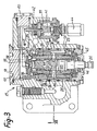
- the other pair of bores 29 opens into longitudinal channels connected to the return to the cover by means of the cavities located between the body 24 and the fur 23 (FIG. 3).
- the two pairs of adjacent bore 29a and coaxial bore 31a are connected respectively with U1 and U2.
- the external surface of the plug 19 is machined so as to present a series of notches 28 which determine passages between two neighboring bores 31 for the hydraulic fluid, and this, progressively taking into account the way these passages are machined, when the plug 19 is rotated in one direction or the other.
- FIG. 7 it can be seen in FIG. 7 that if the plug 19 is rotated clockwise represented by the arrow R, the pressurized oil arriving via the pipe P in the pair of diametrically opposed bores 29, 31, passes through the diametrically opposite adjacent bores 31a, 29a which communicate with the use U1, and this with a flow proportional to the angle of rotation of the plug 19.
- the oil coming from the channel U2 passes with an increasing flow in the bores and openings 29a, 31a a which open into the return pipe R.
- This circulation of the hydraulic fluid is symbolized by the arrows shown in FIG. 7.
- the invention provides for arranging on the periphery of the cylindrical element 22, a series of passages machined 33 in correspondence with the passages 28. These openings 33 provide direct communication between the pairs of bores 29 and the pairs of adjacent bores, if the annular element 22 is rotated, for example clockwise R; the transition to progressive flow of oil from one bore 29 to the next is represented by arrows in FIG. 7, in the case of the transfer of oil from the pressure line P to use U1.
- the annular element 22 remains fixed in rotation in the position shown in FIG. 7.
- Each peripheral passage 28 of the plug 19 is therefore in a way doubled by a corresponding peripheral passage 33, machined so as to also ensure a transfer at progressive flow rate of the oil from a radial bore to the neighboring bore, if the element annular 22 is rotated, in order to ensure the planned oil distribution.
- Locking means are arranged to keep the annular element 22 normally fixed when the plug 19 rotates, and to allow this element 22 to be driven in rotation by the plug 19 in the event of the latter jamming in said annular element. .
- these locking means comprise balls 34 of which only one is visible in FIG. 3, these balls being for example three in number distant from equal angular deviations, and partially engaged in corresponding notches 35 to V-shaped ramps machined on the end of the annular element 22 opposite the actuating lever.
- the balls 34 can slide in circular openings 40, arranged in a guide 36 fixed to the body 24 by a rod 10 and the plug 50.
- the locking device also comprises a plate 37 elastically urged against the balls 34 by a balance 38 pushed itself by an elastic member constituted in the example represented by a helical spring 39 housed in the body 24.
- the pendulum 38 and the plate 37 are placed in a chamber of the body 24 closed by plugs 50 and 60 screwed into the latter.
- the spring 39 acts on the end of the balance 38 by means of a pusher 41 comprising a rod 42.
- the balance 38 is articulated around an axis 43 carried by the body 24.
- the pusher 41 cooperates with an electrical contactor 44 connected to an alarm lamp, not shown, and which can be lit when the balls 34 push the pendulum 38 against the action of the return spring 39 correlatively to a rotation of the annular element 22, as will be explained in more detail below.
- the annular element 22 is mounted on a ball bearing 45 used as a frictionless stop on the side opposite the balls 34, and cooperates with a ball stop 46 coaxial with the plug 19 and located in the vicinity of the bearing 45.
- the dispenser is provided, according to an important feature of the invention, with a device for testing the proper functioning of the locking means (34, 37, 38, 42, 43, 41, 39) of the annular element 22 relative to the rotary valve 19, this device being visible in particular in FIGS. 2 and 5.
- a jack 47 housed in a lateral protuberance 48 of the body 24, and which can be actuated by an elastic member constituted in the example represented by a helical spring 49.
- the latter bears against a cap 60 screwed into the 'protuberance 48 and which also serves as a stopper for the actuator proper 47.
- the spring 49 exerts a constant stress on an internal shoulder of the actuator 47 so as to push the rod 51 of the latter against a radial arm 52 forming part of a collar 53 mounted at the end of the annular element 22 where the locking balls 34 are located, and secured to the element 22 in rotation by a pin 55 ( Figure 5).
- the jack 47 is positioned in a cylindrical chamber 56 communicating with the hydraulic supply circuit by a pipe 57.
- the pipe 61 communicates with the channel P of the annular part 25.
- the rod 51 on its side is housed in a bore 58 which is separated from the chamber 56 in a leaktight manner by an annular seal 59 embedded in the periphery of the jack 47.
- the thrust of the spring 49 on the jack 47 is exerted without compensation, so that the rod 51 comes into contact with the arm 52 which pivots and rotates, clockwise, the collar 53, as indicated by the arrows in FIG. 5.
- the latter in turn rotates the annular element 22 by means of the pin 55, so that the balls 34 are pushed towards the outside of their notches 35, slide on the inclined ramps thereof, slide in the openings for passage of the guide 36, and rotate the balance 38 around its axis 43.
- the push-button 41, 42 triggers the switch contactor 44 which in turn turns on the alarm lamp, this consequently indicating to the operator that the element 22 is unlocked from its normal position.
- the pipe 61 is isolated from the pipe 57 by the jack 47.
- the plug 19 can no longer rotate relative to the element 22, the latter is driven in rotation by the plug 19 from the moment when the torque exerted by the plug becomes greater than the locking torque exerted on the annular element 22 by the balls 34 under the thrust of the plate 37 and the spring 39, via the pendulum 38.
- the annular element 22 rotates coaxially with the plug 19 and integrally with the latter, and the balls 34 are gradually pushed back outside their notches 35 by pivoting the pendulum 38 in the direction antagonistic to the thrust of the return spring 39, as explained above.
- the distributor according to the invention is considerably more advantageous than the known embodiments, since it makes the mounting of two identical interconnected distributors superfluous to ensure normal hydraulic supply in the event of failure of one of them.
- the hydraulic distributor according to the invention is therefore much less heavy and bulky than the known devices, and also less expensive. Its reliability is excellent, since there is no reason for the annular element 22 to be capable of being itself blocked with respect to the fixed fur 23.
- the locking system test device (34, 37, 38, 42, 43, 41, 39) of the annular element 22 by means of the jack 47 and its thrust spring 49 advantageously allows the pilot to verify the correct operation of this safety system, the hydraulic chamber 56 being depressurized.
- the pilot pressurizes this chamber, and the annular element 22 automatically returns to its normal position, under the elastic stress exerted by the return device (39, 41), the balls 34 returning to the bottom of their notches 35 in their normal position.
- the pressure test device of the locking system of the element 22 can be replaced by any other equivalent means. It is also possible, depending on the available volume, to place the assembly: spring 39, pusher 41, 42 and contactor 44 in the extension of the axis of the distributor, which eliminates the lever 38, the axis 43 and the ancillary elements. .
Landscapes
- Engineering & Computer Science (AREA)
- Physics & Mathematics (AREA)
- Fluid Mechanics (AREA)
- Mechanical Engineering (AREA)
- General Engineering & Computer Science (AREA)
- Chemical & Material Sciences (AREA)
- Analytical Chemistry (AREA)
- Fluid-Pressure Circuits (AREA)
- Actuator (AREA)
Applications Claiming Priority (2)
| Application Number | Priority Date | Filing Date | Title |
|---|---|---|---|
| FR7917184A FR2460435A1 (fr) | 1979-07-03 | 1979-07-03 | Distributeur hydraulique, destine notamment a equiper des servo-commandes d'avions et d'helicopteres |
| FR7917184 | 1979-07-03 |
Publications (2)
| Publication Number | Publication Date |
|---|---|
| EP0021977A1 EP0021977A1 (fr) | 1981-01-07 |
| EP0021977B1 true EP0021977B1 (fr) | 1982-12-29 |
Family
ID=9227411
Family Applications (1)
| Application Number | Title | Priority Date | Filing Date |
|---|---|---|---|
| EP80400878A Expired EP0021977B1 (fr) | 1979-07-03 | 1980-06-17 | Distributeur hydraulique, destiné notamment à équiper des servo-commandes d'avions et d'hélicoptères |
Country Status (4)
| Country | Link |
|---|---|
| US (1) | US4335745A (,) |
| EP (1) | EP0021977B1 (,) |
| DE (1) | DE3061498D1 (,) |
| FR (1) | FR2460435A1 (,) |
Families Citing this family (20)
| Publication number | Priority date | Publication date | Assignee | Title |
|---|---|---|---|---|
| JPS5853568A (ja) * | 1981-09-22 | 1983-03-30 | Koyo Jidoki Kk | パワ−ステアリング装置の回転制御弁 |
| JPS6015265A (ja) * | 1983-07-04 | 1985-01-25 | Toyoda Mach Works Ltd | サ−ボバルブ |
| FR2549167B1 (fr) * | 1983-07-13 | 1988-01-29 | Applic Mach Motrices | Distributeur hydraulique destine a equiper une commande d'aeronef |
| US4694849A (en) * | 1984-07-23 | 1987-09-22 | Rampen William H S | Hydraulic control valves |
| US4569371A (en) * | 1984-12-28 | 1986-02-11 | Uop Inc. | Axial multiport rotary valve |
| EP0231568B1 (en) * | 1986-02-06 | 1990-05-23 | Uop | Multiport axial valve with balanced rotor |
| DE3667840D1 (de) * | 1986-02-06 | 1990-02-01 | Uop Inc | Axiales mehrwegesdrehventil. |
| FR2610072B1 (fr) * | 1987-01-22 | 1989-05-19 | Applic Mach Motrices | Servovalve electrohydraulique pour la commande asservie d'un actionneur hydraulique, notamment dans les servomecanismes de commande de vol des aeronefs |
| FR2747174B1 (fr) * | 1996-04-03 | 1998-07-10 | Samm Societe D Applic Des Mach | Distributeur hydraulique pour servocommandes d'aeronefs, notamment helicopteres |
| US5979504A (en) * | 1996-05-02 | 1999-11-09 | Caterpillar Inc. | Rotary control valve |
| DE19926429A1 (de) * | 1999-06-10 | 2000-12-14 | Zf Luftfahrttechnik Gmbh | Einrichtung zum gleichzeitigen Verriegeln mehrerer Aktuatoren |
| GB0310969D0 (en) * | 2003-05-13 | 2003-06-18 | Ricardo Uk Linmited | Clutches |
| FR2916492B1 (fr) * | 2007-05-24 | 2009-07-17 | Eurocopter France | Distributeur hydraulique muni d'un dispositif de detection de grippage. |
| GB201116679D0 (en) * | 2011-09-28 | 2011-11-09 | Goodrich Actuation Systems Sas | Rotary control valve |
| CN103759043B (zh) * | 2014-01-02 | 2016-08-17 | 武汉船用机械有限责任公司 | 一种转阀 |
| GB2522744B (en) | 2014-11-14 | 2016-03-16 | Blagdon Actuation Res Ltd | Servo actuators |
| EP3309063A1 (en) | 2016-10-14 | 2018-04-18 | Goodrich Actuation Systems SAS | Actuator control arrangement |
| CN111531529B (zh) * | 2020-06-11 | 2024-10-11 | 常州工业职业技术学院 | 防止气缸失效式气动连杆机械手 |
| WO2022192698A1 (en) | 2021-03-12 | 2022-09-15 | Essex Industries, Inc., | Rocker switch |
| EP4309200A1 (en) | 2021-03-15 | 2024-01-24 | Essex Industries, Inc. | Five-position switch |
Family Cites Families (7)
| Publication number | Priority date | Publication date | Assignee | Title |
|---|---|---|---|---|
| US2384760A (en) * | 1945-04-13 | 1945-09-11 | Matullonis Edward | Fluid-pressure operated apparatus |
| US3482486A (en) * | 1967-11-29 | 1969-12-09 | United Aircraft Corp | Redundant control method and apparatus |
| US3591139A (en) * | 1968-03-20 | 1971-07-06 | Arthur E Bishop | Method and apparatus for making valve sleeves |
| US3529514A (en) * | 1969-03-25 | 1970-09-22 | United Aircraft Corp | Redundant servomechanism with bypass provisions |
| US3707167A (en) * | 1970-06-25 | 1972-12-26 | Trw Inc | Hydraulic controller including rotary valve |
| GB1578928A (en) * | 1976-05-25 | 1980-11-12 | Fairey Hydraulics | Servo systems having at least two servo mechanisms |
| US4040338A (en) * | 1976-06-14 | 1977-08-09 | Logansport Machine Co., Inc. | Fluid supply distributor |
-
1979
- 1979-07-03 FR FR7917184A patent/FR2460435A1/fr active Granted
-
1980
- 1980-06-17 DE DE8080400878T patent/DE3061498D1/de not_active Expired
- 1980-06-17 EP EP80400878A patent/EP0021977B1/fr not_active Expired
- 1980-06-26 US US06/163,382 patent/US4335745A/en not_active Expired - Lifetime
Also Published As
| Publication number | Publication date |
|---|---|
| EP0021977A1 (fr) | 1981-01-07 |
| FR2460435A1 (fr) | 1981-01-23 |
| FR2460435B1 (,) | 1981-07-31 |
| US4335745A (en) | 1982-06-22 |
| DE3061498D1 (en) | 1983-02-03 |
Similar Documents
| Publication | Publication Date | Title |
|---|---|---|
| EP0021977B1 (fr) | Distributeur hydraulique, destiné notamment à équiper des servo-commandes d'avions et d'hélicoptères | |
| EP0935715B1 (fr) | Dispositif de maintien en position de la tige d'un verin hydraulique | |
| BE1006434A3 (fr) | Commande d'au moins deux bras de stabilisation dans un dispositif de forage ou de carottage. | |
| EP0117806B1 (fr) | Dispositif distributeur de fluide, notamment pour télécommande | |
| EP0272176A1 (fr) | Dispositif actionneur hydraulique rotatif à palette, destiné notamment à l'entrainement d'une gouverne d'aéronef | |
| FR2616856A1 (fr) | Mecanisme de commande d'ecartement rapide et controle de deux pieces en contact | |
| EP0282417A1 (fr) | Dispositif de changement d'outil de robot | |
| FR2593261A1 (fr) | Structure de valves a fluide | |
| FR2748298A1 (fr) | Dispositif de verin pneumatique | |
| EP0546895B1 (fr) | Dispositif à vulnérabilité réduite pour la commande d'un rotor d'hélicoptère par plateaux cycliques | |
| EP1342645A1 (fr) | Architecture de système hydraulique de commande d'orientation | |
| FR2549167A1 (fr) | Distributeur hydraulique destine a equiper une commande d'aeronef | |
| EP0459840B1 (fr) | Dispositif de commande d'un vérin hydraulique à double effet | |
| FR2517791A1 (fr) | Perfectionnements apportes aux distributeurs hydrauliques | |
| FR2522109A1 (fr) | Soupape a regeneration | |
| EP2383456B1 (fr) | Vérin hydraulique simple effet | |
| EP0197858B1 (fr) | Correcteur de garde au sol pour élément de suspension d'un véhicule lourd | |
| EP0270463A1 (fr) | Vérin hydraulique ou pneumatique dont l'élément mobile en translation est immobilisé en rotation autour de son axe longitudinal | |
| EP0176381A1 (fr) | Distributeur hydraulique haute pression, à générateur de pression de pilotage | |
| FR2566352A1 (fr) | Amplificateur hydraulique d'effort de freinage | |
| EP0801232A1 (fr) | Distributeur hydraulique pour servocommandes d'aéronefs, notamment hélicoptères | |
| EP4168309B1 (fr) | Dispositif de verrouillage d'atterrisseur | |
| FR2572786A1 (fr) | Deconnecteur d'urgence pour bras de chargement ou de dechargement d'un vehicule de transport de fluide | |
| FR2545183A1 (fr) | Soupape de commande a mecanisme de securite | |
| EP0601912B1 (fr) | Systèmes de vérins à trois positions de fonctionnement stables |
Legal Events
| Date | Code | Title | Description |
|---|---|---|---|
| PUAI | Public reference made under article 153(3) epc to a published international application that has entered the european phase |
Free format text: ORIGINAL CODE: 0009012 |
|
| AK | Designated contracting states |
Designated state(s): DE GB IT |
|
| 17P | Request for examination filed |
Effective date: 19810324 |
|
| ITF | It: translation for a ep patent filed | ||
| GRAA | (expected) grant |
Free format text: ORIGINAL CODE: 0009210 |
|
| AK | Designated contracting states |
Designated state(s): DE GB IT |
|
| REF | Corresponds to: |
Ref document number: 3061498 Country of ref document: DE Date of ref document: 19830203 |
|
| ITTA | It: last paid annual fee | ||
| PGFP | Annual fee paid to national office [announced via postgrant information from national office to epo] |
Ref country code: GB Payment date: 19990420 Year of fee payment: 20 |
|
| PGFP | Annual fee paid to national office [announced via postgrant information from national office to epo] |
Ref country code: DE Payment date: 19990423 Year of fee payment: 20 |
|
| PG25 | Lapsed in a contracting state [announced via postgrant information from national office to epo] |
Ref country code: GB Free format text: LAPSE BECAUSE OF EXPIRATION OF PROTECTION Effective date: 20000616 |
|
| REG | Reference to a national code |
Ref country code: GB Ref legal event code: PE20 Effective date: 20000616 |
|
| PLBE | No opposition filed within time limit |
Free format text: ORIGINAL CODE: 0009261 |
|
| STAA | Information on the status of an ep patent application or granted ep patent |
Free format text: STATUS: NO OPPOSITION FILED WITHIN TIME LIMIT |