EP0021895B1 - Vanne de sécurité à ouverture par cisaillement d'un conduit borgne - Google Patents
Vanne de sécurité à ouverture par cisaillement d'un conduit borgne Download PDFInfo
- Publication number
- EP0021895B1 EP0021895B1 EP80400767A EP80400767A EP0021895B1 EP 0021895 B1 EP0021895 B1 EP 0021895B1 EP 80400767 A EP80400767 A EP 80400767A EP 80400767 A EP80400767 A EP 80400767A EP 0021895 B1 EP0021895 B1 EP 0021895B1
- Authority
- EP
- European Patent Office
- Prior art keywords
- conduit
- blind
- shearing
- safety valve
- piston
- Prior art date
- Legal status (The legal status is an assumption and is not a legal conclusion. Google has not performed a legal analysis and makes no representation as to the accuracy of the status listed.)
- Expired
Links
- 238000010008 shearing Methods 0.000 title claims description 12
- 239000012530 fluid Substances 0.000 claims description 15
- 239000007789 gas Substances 0.000 claims description 5
- 239000002245 particle Substances 0.000 description 4
- 230000015572 biosynthetic process Effects 0.000 description 2
- 238000010276 construction Methods 0.000 description 2
- 238000013016 damping Methods 0.000 description 2
- 230000001627 detrimental effect Effects 0.000 description 2
- 238000006073 displacement reaction Methods 0.000 description 2
- 239000002360 explosive Substances 0.000 description 2
- 230000002093 peripheral effect Effects 0.000 description 2
- 238000011144 upstream manufacturing Methods 0.000 description 2
- 230000003313 weakening effect Effects 0.000 description 2
- 238000004891 communication Methods 0.000 description 1
- 239000004020 conductor Substances 0.000 description 1
- 238000002347 injection Methods 0.000 description 1
- 239000007924 injection Substances 0.000 description 1
- 239000000463 material Substances 0.000 description 1
- 230000003068 static effect Effects 0.000 description 1
Images
Classifications
-
- F—MECHANICAL ENGINEERING; LIGHTING; HEATING; WEAPONS; BLASTING
- F16—ENGINEERING ELEMENTS AND UNITS; GENERAL MEASURES FOR PRODUCING AND MAINTAINING EFFECTIVE FUNCTIONING OF MACHINES OR INSTALLATIONS; THERMAL INSULATION IN GENERAL
- F16K—VALVES; TAPS; COCKS; ACTUATING-FLOATS; DEVICES FOR VENTING OR AERATING
- F16K17/00—Safety valves; Equalising valves, e.g. pressure relief valves
- F16K17/40—Safety valves; Equalising valves, e.g. pressure relief valves with a fracturing member, e.g. fracturing diaphragm, glass, fusible joint
- F16K17/403—Safety valves; Equalising valves, e.g. pressure relief valves with a fracturing member, e.g. fracturing diaphragm, glass, fusible joint with a fracturing valve member
-
- F—MECHANICAL ENGINEERING; LIGHTING; HEATING; WEAPONS; BLASTING
- F16—ENGINEERING ELEMENTS AND UNITS; GENERAL MEASURES FOR PRODUCING AND MAINTAINING EFFECTIVE FUNCTIONING OF MACHINES OR INSTALLATIONS; THERMAL INSULATION IN GENERAL
- F16K—VALVES; TAPS; COCKS; ACTUATING-FLOATS; DEVICES FOR VENTING OR AERATING
- F16K13/00—Other constructional types of cut-off apparatus; Arrangements for cutting-off
- F16K13/04—Other constructional types of cut-off apparatus; Arrangements for cutting-off with a breakable closure member
- F16K13/06—Other constructional types of cut-off apparatus; Arrangements for cutting-off with a breakable closure member constructed to be ruptured by an explosion
Definitions
- the invention relates to a safety valve with shear opening of a blind pipe, intended in particular to allow the rapid communication of two chambers containing fluids at different pressures, this safety valve comprising a body which is provided with a part of at least one conduit terminated by this blind conduit having a zone of embrittlement and on the other hand a shear rupture device which is a translation device comprising a piston controlled by fluid pressure.
- Safety valves with shear opening of a shutter such as a blind conduit are known, and are sometimes also designated by the terms of valve or valve, and for example FR-A-2135 609 and FR-A-2 242,622 describe two particular types of these valves.
- FR-A-2 135 609 and in particular according to FIGS. 4a and 4b it is described that the blind pipe ends in a disc whose peripheral shearing is obtained by a traction exerted along the axis of this disc, which leads necessarily that the escaping fluid is diverted, since after rupture, the disc is located opposite the inlet of the pressurized fluid.
- Such a type of valve therefore tends to form by friction particles such as chips or filings, which can be detrimental to the proper functioning of a safety valve, especially when the evacuated fluid must be routed in a difficult network of pipes. to be purged or fitted with equipment which may be damaged by these particles.
- the present invention aims, on the one hand to avoid any formation of particles resulting from the friction of the two sheared sections, and on the other hand, to reduce the pressure losses of the evacuated fluid passing through the safety valve, and characterized in that the rupture device moves in a plane which is inclined relative to the plane defined by the zone of weakness of the blind conduit, the angle of inclination being between 0.5 degree and 45 degrees, this inclination being such that after shearing, the section of the end portion of the blind pipe tends to deviate from the section secured to the pipe of the valve body.
- the inclination of the two planes is greater than 0.5 degrees, so that the spacing of the two sheared sections is sufficient so that the shear burrs do not come into contact, and is less than 45 degrees, so as not to unnecessarily increase the perimeter of the embrittlement area.
- this inclination is between 1 and 10 degrees, small inclinations being admissible when the material constituting the obturator has mechanical characteristics allowing shearing with few burrs.
- the piston comprises downstream a guillotine provided with two lights, one of which surrounds the end portion of the blind conduit, the second lumen being intended for the passage of the fluid when the piston occupies its final position after shearing of the conduit blind, and according to a second variant, the piston comprises downstream a striker acting on the end part of the blind conduit.
- the embrittlement zone of the blind conduit is contained in a plane orthogonal to this conduit, and the rupture device is inclined relative to this orthogonal plane, while according to another construction method, the zone of embrittlement is contained in a plane inclined with respect to a plane orthogonal to the closed conduit and the rupture device moves in a plane orthogonal to this conduit.
- the blind conduit comprises two weakening zones arranged on either side of the terminal part of this conduit.
- the rupture device is actuated by the gas of a combustible or explosive pyrotechnic charge.
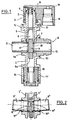
- FIG. 1 corresponding to a valve whose rupture device is contained in a plane orthogonal to the axis of the blind conduit
- FIG. 2 corresponding to a valve similar to the valve shown felt in Figure 1, and being limited to only the elements which are different
- Figure '3 corresponding to a valve whose rupture device is inclined relative to a plane orthogonal to the axis of the conduit.
- the safety valve with shear opening comprises a hollow body 1, the two parallel lateral flanges of which are each provided with a reamed lateral boss 1 a and 1b, and the upper and lower parts of which also end in bosses 1c and 1d which allow the fixing of the centering elements of the translation device 2.
- the cylinder 3 of the translation jack is fixed on the upper boss 1c of the body and ensures the guiding of the cylindrical piston 4 which comprises downstream a guillotine 5 provided with two openings 6 and 7, the double blind conduit 8 being engaged in the lower lumen and this conduit welded to the lateral bosses being provided with two bores 9 and 10 which provide the end portion 1'1 situated in line with this guillotine 5.
- the weakening zones of the blind conduit consist of two grooves 17 and 18 with a v-shaped section which are cut on the outside and, according to the invention, these two grooves are produced according to ux oblique planes whose inclination is 5 degrees relative to the plane orthogonal to the conduit passing through the axis of the piston 4, the fictitious dihedron of intersection of the two oblique planes being located upstream of the piston.
- the outer part of the cylinder '3 is threaded and allows the fixing by the lock nut 12 of the injection head 13 of the working fluid, the high pressure gas generator cartridge (not shown) being engaged in the bore 14 which communicates with the interior of the cylinder by the hole 15.
- the lower boss 1d is also threaded and receives the damping device 16 which limits the displacement of the piston 4 after shearing and ensures its positioning by means of the deformable tubular ring '19 which cooperates with the terminal cone 5a of the guillotine 5.
- the safety valve with shear opening represented partially in FIG. 2 is in all points similar to the valve represented in FIG. 1, with the exception of the central part which is the subject of this FIG. 2.
- the lateral bosses of the hollow body 1 ' are bored obliquely and symmetrically with respect to the median plane of the guillotine 5' so that these bores are inclined towards the lower internal part of this hollow body.
- Each bore of the lateral bosses receives a blind duct 8 'and 8 "in all identical points, the end portions 11' and 11" of these blind ducts being engaged in the lower lumen of the guillotine 5 ', and the circular grooves with cross-section vee 17 'and 18 "being contained in planes respectively orthogonal to the axes of the blind conduits 8' and 8".
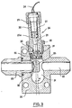
- the tubing 23 comprises a shutter, the end portion of which '25 is delimited by the zone of weakness determined by the groove in v-section 35 which cuts the periphery of this tubing at the level of the central recess 21, the bottom of this groove being contained in a plane orthogonal to the axis of the bore 22.
- the upper bore comprises a shoulder which allows the positioning of the lid of Leakproofness' 26 on which the cylinder 27 of the translatory actuator which is immobilized by the threaded ring 28, and inside the cylinder can slide the piston 29 temporarily immobilized on the one hand by means of the support washer 30 secured to the downstream part of the piston by the shear pin 31 and on the other leaves by means of the pyrotechnic cartridge '32 which is fixed to the upstream end of the cylinder by means of the threaded ring 33.
- the pyrotechnic cartridge comprises an explosive charge which can be ignited by means of the two-wire conductor' 34 when the van Security must be open.
- the gas generated acts on the head 29a of the piston and successively causes the pin 31 to break and the piston to move, the downstream part of which is shaped as a striker, so as to puncture the seal d seal 26 and to be embedded in the end portion 25 of the shutter, which is sheared along the bottom of the groove 35 and which is driven to the bottom of the recess 21 without there being friction between the section of the terminal part of the obturator and the integral section of the tubing 23.
- the pressurized fluid present in the tubing 23 can escape through the bore 22 and the static pressure of this fluid in the recess 21 is sufficient to ensure the ascent of the piston 29a as soon as the gases produced by the pyrotechnic charge have been evacuated by the leaks which exist between the cartridge 32, the cylinder '27 and the threaded ring '33, the evacuation pressurized fluid which can s be carried out without any obstacle between the bore of the tubing 23 and the bore 22, and the sheared part of the brittle tubing which can if necessary be immobilized at the bottom of the recess 21 by a damping and positioning device like the one shown in figure 1.
Landscapes
- Engineering & Computer Science (AREA)
- General Engineering & Computer Science (AREA)
- Mechanical Engineering (AREA)
- Safety Valves (AREA)
Applications Claiming Priority (2)
| Application Number | Priority Date | Filing Date | Title |
|---|---|---|---|
| FR7914538 | 1979-06-07 | ||
| FR7914538A FR2458731A1 (fr) | 1979-06-07 | 1979-06-07 | Vanne de securite a ouverture par cisaillement d'un conduit borgne |
Publications (2)
| Publication Number | Publication Date |
|---|---|
| EP0021895A1 EP0021895A1 (fr) | 1981-01-07 |
| EP0021895B1 true EP0021895B1 (fr) | 1982-12-01 |
Family
ID=9226306
Family Applications (1)
| Application Number | Title | Priority Date | Filing Date |
|---|---|---|---|
| EP80400767A Expired EP0021895B1 (fr) | 1979-06-07 | 1980-05-30 | Vanne de sécurité à ouverture par cisaillement d'un conduit borgne |
Country Status (3)
| Country | Link |
|---|---|
| EP (1) | EP0021895B1 (enExample) |
| DE (1) | DE3061202D1 (enExample) |
| FR (1) | FR2458731A1 (enExample) |
Families Citing this family (3)
| Publication number | Priority date | Publication date | Assignee | Title |
|---|---|---|---|---|
| CN103759051A (zh) * | 2014-01-21 | 2014-04-30 | 大连大高阀门股份有限公司 | 核电站用爆破阀的密封结构 |
| DE102015014797A1 (de) | 2015-11-14 | 2017-05-18 | Hydac Technology Gmbh | Sicherheitsvorrichtung |
| CN109237048B (zh) * | 2018-09-29 | 2023-09-22 | 山西江淮重工有限责任公司 | 一种火药装药用密封放料阀 |
Citations (2)
| Publication number | Priority date | Publication date | Assignee | Title |
|---|---|---|---|---|
| FR2135609A1 (enExample) * | 1971-05-06 | 1972-12-22 | Dynamit Nobel Ag | |
| FR2242622A1 (en) * | 1973-08-28 | 1975-03-28 | Cbf Systems Inc | Explosive actuated valve with shearing device - provides rapid opening for actuation of fire extinguisher |
Family Cites Families (1)
| Publication number | Priority date | Publication date | Assignee | Title |
|---|---|---|---|---|
| US3093151A (en) * | 1958-09-12 | 1963-06-11 | Gen Dynamics Corp | Shear valve and frangible fitting |
-
1979
- 1979-06-07 FR FR7914538A patent/FR2458731A1/fr active Granted
-
1980
- 1980-05-30 EP EP80400767A patent/EP0021895B1/fr not_active Expired
- 1980-05-30 DE DE8080400767T patent/DE3061202D1/de not_active Expired
Patent Citations (2)
| Publication number | Priority date | Publication date | Assignee | Title |
|---|---|---|---|---|
| FR2135609A1 (enExample) * | 1971-05-06 | 1972-12-22 | Dynamit Nobel Ag | |
| FR2242622A1 (en) * | 1973-08-28 | 1975-03-28 | Cbf Systems Inc | Explosive actuated valve with shearing device - provides rapid opening for actuation of fire extinguisher |
Also Published As
| Publication number | Publication date |
|---|---|
| FR2458731B1 (enExample) | 1982-03-26 |
| DE3061202D1 (en) | 1983-01-05 |
| EP0021895A1 (fr) | 1981-01-07 |
| FR2458731A1 (fr) | 1981-01-02 |
Similar Documents
| Publication | Publication Date | Title |
|---|---|---|
| FR2556065A1 (fr) | Dispositif de connexion mecanique | |
| FR2653199A1 (fr) | Soupape de commande d'ecoulement d'un fluide dans une conduite de transport de fluide dans un puits souterrain et procede pour faire fonctionner une soupape de fond de puits. | |
| FR2569761A1 (fr) | Procede et appareillage pour arreter la production d'un puits | |
| FR2564522A1 (fr) | Soupape de surete | |
| FR2578577A1 (fr) | Procede et dispositif de mise hors service d'une vanne de securite de puits par verrouillage dans la position d'ouverture | |
| EP0280600B1 (fr) | Tendeur à commande hydraulique, notamment pour chaine | |
| BE1009965A3 (fr) | Carottier. | |
| FR2563272A1 (fr) | Appareillage de sectionnement de ligne de service dans un puits de petrole ou de gaz | |
| FR2560632A1 (fr) | Appareil de mise en place d'outils de forage, de completion ou de reconditionnement de puits et appareil a vanne a graisseur | |
| FR2704924A1 (fr) | Vanne pyrotechnique. | |
| EP0021895B1 (fr) | Vanne de sécurité à ouverture par cisaillement d'un conduit borgne | |
| EP3092368B1 (fr) | Dispositif d'isolation pour puits | |
| CA1024887A (fr) | Vannes de securite hydraulique | |
| EP0874947B1 (fr) | Procede de carottage et carottier pour sa mise en oeuvre | |
| EP0655574B1 (fr) | Dispositif d'ouverture et de fermeture de sécurité d'un robinet vanne | |
| FR2487091A1 (fr) | Dispositif de commande electro-hydraulique | |
| EP1380779B1 (fr) | Clapet de pression résiduelle | |
| FR2562667A1 (fr) | Dispositif combine d'etancheite et de retenue pour epreuve de tubes par fluide sous pression | |
| FR2692003A1 (fr) | Procédé et dispositif de contrôle de l'intégrité physique de tubes d'extraction et de gainages d'extraction dans des puits d'extraction par gaz. | |
| FR2666116A1 (fr) | Vanne de securite de l'espace annulaire et procede pour commander l'ecoulement de fluides entre des conduits tubulaires exterieur et interieur. | |
| EP3102775B1 (fr) | Dispositif expansible | |
| FR2576966A1 (fr) | Ensemble de securite annulaire pour puits petrolier, en particulier a double zone de production | |
| EP0656497B1 (fr) | Dispositif de sécurité d'une vanne rotative | |
| WO2018060594A1 (fr) | Dispositif de distribution d'un materiau pressurise | |
| FR2501820A1 (fr) | Vanne a passage direct en tout ou rien |
Legal Events
| Date | Code | Title | Description |
|---|---|---|---|
| PUAI | Public reference made under article 153(3) epc to a published international application that has entered the european phase |
Free format text: ORIGINAL CODE: 0009012 |
|
| AK | Designated contracting states |
Designated state(s): DE GB IT SE |
|
| 17P | Request for examination filed |
Effective date: 19810427 |
|
| ITF | It: translation for a ep patent filed | ||
| GRAA | (expected) grant |
Free format text: ORIGINAL CODE: 0009210 |
|
| AK | Designated contracting states |
Designated state(s): DE GB IT SE |
|
| REF | Corresponds to: |
Ref document number: 3061202 Country of ref document: DE Date of ref document: 19830105 |
|
| ITTA | It: last paid annual fee | ||
| EAL | Se: european patent in force in sweden |
Ref document number: 80400767.2 |
|
| PGFP | Annual fee paid to national office [announced via postgrant information from national office to epo] |
Ref country code: GB Payment date: 19950519 Year of fee payment: 16 |
|
| PGFP | Annual fee paid to national office [announced via postgrant information from national office to epo] |
Ref country code: SE Payment date: 19950522 Year of fee payment: 16 |
|
| PGFP | Annual fee paid to national office [announced via postgrant information from national office to epo] |
Ref country code: DE Payment date: 19950728 Year of fee payment: 16 |
|
| PG25 | Lapsed in a contracting state [announced via postgrant information from national office to epo] |
Ref country code: GB Effective date: 19960530 |
|
| PG25 | Lapsed in a contracting state [announced via postgrant information from national office to epo] |
Ref country code: SE Effective date: 19960531 |
|
| GBPC | Gb: european patent ceased through non-payment of renewal fee |
Effective date: 19960530 |
|
| PG25 | Lapsed in a contracting state [announced via postgrant information from national office to epo] |
Ref country code: DE Effective date: 19970201 |
|
| EUG | Se: european patent has lapsed |
Ref document number: 80400767.2 |
|
| PLBE | No opposition filed within time limit |
Free format text: ORIGINAL CODE: 0009261 |
|
| STAA | Information on the status of an ep patent application or granted ep patent |
Free format text: STATUS: NO OPPOSITION FILED WITHIN TIME LIMIT |