EP0021895B1 - Security valve to be opened by shearing the end of a closed conduit - Google Patents
Security valve to be opened by shearing the end of a closed conduit Download PDFInfo
- Publication number
- EP0021895B1 EP0021895B1 EP80400767A EP80400767A EP0021895B1 EP 0021895 B1 EP0021895 B1 EP 0021895B1 EP 80400767 A EP80400767 A EP 80400767A EP 80400767 A EP80400767 A EP 80400767A EP 0021895 B1 EP0021895 B1 EP 0021895B1
- Authority
- EP
- European Patent Office
- Prior art keywords
- conduit
- blind
- shearing
- safety valve
- piston
- Prior art date
- Legal status (The legal status is an assumption and is not a legal conclusion. Google has not performed a legal analysis and makes no representation as to the accuracy of the status listed.)
- Expired
Links
Images
Classifications
-
- F—MECHANICAL ENGINEERING; LIGHTING; HEATING; WEAPONS; BLASTING
- F16—ENGINEERING ELEMENTS AND UNITS; GENERAL MEASURES FOR PRODUCING AND MAINTAINING EFFECTIVE FUNCTIONING OF MACHINES OR INSTALLATIONS; THERMAL INSULATION IN GENERAL
- F16K—VALVES; TAPS; COCKS; ACTUATING-FLOATS; DEVICES FOR VENTING OR AERATING
- F16K17/00—Safety valves; Equalising valves, e.g. pressure relief valves
- F16K17/40—Safety valves; Equalising valves, e.g. pressure relief valves with a fracturing member, e.g. fracturing diaphragm, glass, fusible joint
- F16K17/403—Safety valves; Equalising valves, e.g. pressure relief valves with a fracturing member, e.g. fracturing diaphragm, glass, fusible joint with a fracturing valve member
-
- F—MECHANICAL ENGINEERING; LIGHTING; HEATING; WEAPONS; BLASTING
- F16—ENGINEERING ELEMENTS AND UNITS; GENERAL MEASURES FOR PRODUCING AND MAINTAINING EFFECTIVE FUNCTIONING OF MACHINES OR INSTALLATIONS; THERMAL INSULATION IN GENERAL
- F16K—VALVES; TAPS; COCKS; ACTUATING-FLOATS; DEVICES FOR VENTING OR AERATING
- F16K13/00—Other constructional types of cut-off apparatus; Arrangements for cutting-off
- F16K13/04—Other constructional types of cut-off apparatus; Arrangements for cutting-off with a breakable closure member
- F16K13/06—Other constructional types of cut-off apparatus; Arrangements for cutting-off with a breakable closure member constructed to be ruptured by an explosion
Definitions
- the invention relates to a safety valve with shear opening of a blind pipe, intended in particular to allow the rapid communication of two chambers containing fluids at different pressures, this safety valve comprising a body which is provided with a part of at least one conduit terminated by this blind conduit having a zone of embrittlement and on the other hand a shear rupture device which is a translation device comprising a piston controlled by fluid pressure.
- Safety valves with shear opening of a shutter such as a blind conduit are known, and are sometimes also designated by the terms of valve or valve, and for example FR-A-2135 609 and FR-A-2 242,622 describe two particular types of these valves.
- FR-A-2 135 609 and in particular according to FIGS. 4a and 4b it is described that the blind pipe ends in a disc whose peripheral shearing is obtained by a traction exerted along the axis of this disc, which leads necessarily that the escaping fluid is diverted, since after rupture, the disc is located opposite the inlet of the pressurized fluid.
- Such a type of valve therefore tends to form by friction particles such as chips or filings, which can be detrimental to the proper functioning of a safety valve, especially when the evacuated fluid must be routed in a difficult network of pipes. to be purged or fitted with equipment which may be damaged by these particles.
- the present invention aims, on the one hand to avoid any formation of particles resulting from the friction of the two sheared sections, and on the other hand, to reduce the pressure losses of the evacuated fluid passing through the safety valve, and characterized in that the rupture device moves in a plane which is inclined relative to the plane defined by the zone of weakness of the blind conduit, the angle of inclination being between 0.5 degree and 45 degrees, this inclination being such that after shearing, the section of the end portion of the blind pipe tends to deviate from the section secured to the pipe of the valve body.
- the inclination of the two planes is greater than 0.5 degrees, so that the spacing of the two sheared sections is sufficient so that the shear burrs do not come into contact, and is less than 45 degrees, so as not to unnecessarily increase the perimeter of the embrittlement area.
- this inclination is between 1 and 10 degrees, small inclinations being admissible when the material constituting the obturator has mechanical characteristics allowing shearing with few burrs.
- the piston comprises downstream a guillotine provided with two lights, one of which surrounds the end portion of the blind conduit, the second lumen being intended for the passage of the fluid when the piston occupies its final position after shearing of the conduit blind, and according to a second variant, the piston comprises downstream a striker acting on the end part of the blind conduit.
- the embrittlement zone of the blind conduit is contained in a plane orthogonal to this conduit, and the rupture device is inclined relative to this orthogonal plane, while according to another construction method, the zone of embrittlement is contained in a plane inclined with respect to a plane orthogonal to the closed conduit and the rupture device moves in a plane orthogonal to this conduit.
- the blind conduit comprises two weakening zones arranged on either side of the terminal part of this conduit.
- the rupture device is actuated by the gas of a combustible or explosive pyrotechnic charge.
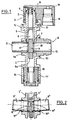
- FIG. 1 corresponding to a valve whose rupture device is contained in a plane orthogonal to the axis of the blind conduit
- FIG. 2 corresponding to a valve similar to the valve shown felt in Figure 1, and being limited to only the elements which are different
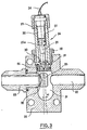
- Figure '3 corresponding to a valve whose rupture device is inclined relative to a plane orthogonal to the axis of the conduit.
- the safety valve with shear opening comprises a hollow body 1, the two parallel lateral flanges of which are each provided with a reamed lateral boss 1 a and 1b, and the upper and lower parts of which also end in bosses 1c and 1d which allow the fixing of the centering elements of the translation device 2.
- the cylinder 3 of the translation jack is fixed on the upper boss 1c of the body and ensures the guiding of the cylindrical piston 4 which comprises downstream a guillotine 5 provided with two openings 6 and 7, the double blind conduit 8 being engaged in the lower lumen and this conduit welded to the lateral bosses being provided with two bores 9 and 10 which provide the end portion 1'1 situated in line with this guillotine 5.
- the weakening zones of the blind conduit consist of two grooves 17 and 18 with a v-shaped section which are cut on the outside and, according to the invention, these two grooves are produced according to ux oblique planes whose inclination is 5 degrees relative to the plane orthogonal to the conduit passing through the axis of the piston 4, the fictitious dihedron of intersection of the two oblique planes being located upstream of the piston.
- the outer part of the cylinder '3 is threaded and allows the fixing by the lock nut 12 of the injection head 13 of the working fluid, the high pressure gas generator cartridge (not shown) being engaged in the bore 14 which communicates with the interior of the cylinder by the hole 15.
- the lower boss 1d is also threaded and receives the damping device 16 which limits the displacement of the piston 4 after shearing and ensures its positioning by means of the deformable tubular ring '19 which cooperates with the terminal cone 5a of the guillotine 5.
- the safety valve with shear opening represented partially in FIG. 2 is in all points similar to the valve represented in FIG. 1, with the exception of the central part which is the subject of this FIG. 2.
- the lateral bosses of the hollow body 1 ' are bored obliquely and symmetrically with respect to the median plane of the guillotine 5' so that these bores are inclined towards the lower internal part of this hollow body.
- Each bore of the lateral bosses receives a blind duct 8 'and 8 "in all identical points, the end portions 11' and 11" of these blind ducts being engaged in the lower lumen of the guillotine 5 ', and the circular grooves with cross-section vee 17 'and 18 "being contained in planes respectively orthogonal to the axes of the blind conduits 8' and 8".
- the tubing 23 comprises a shutter, the end portion of which '25 is delimited by the zone of weakness determined by the groove in v-section 35 which cuts the periphery of this tubing at the level of the central recess 21, the bottom of this groove being contained in a plane orthogonal to the axis of the bore 22.
- the upper bore comprises a shoulder which allows the positioning of the lid of Leakproofness' 26 on which the cylinder 27 of the translatory actuator which is immobilized by the threaded ring 28, and inside the cylinder can slide the piston 29 temporarily immobilized on the one hand by means of the support washer 30 secured to the downstream part of the piston by the shear pin 31 and on the other leaves by means of the pyrotechnic cartridge '32 which is fixed to the upstream end of the cylinder by means of the threaded ring 33.
- the pyrotechnic cartridge comprises an explosive charge which can be ignited by means of the two-wire conductor' 34 when the van Security must be open.
- the gas generated acts on the head 29a of the piston and successively causes the pin 31 to break and the piston to move, the downstream part of which is shaped as a striker, so as to puncture the seal d seal 26 and to be embedded in the end portion 25 of the shutter, which is sheared along the bottom of the groove 35 and which is driven to the bottom of the recess 21 without there being friction between the section of the terminal part of the obturator and the integral section of the tubing 23.
- the pressurized fluid present in the tubing 23 can escape through the bore 22 and the static pressure of this fluid in the recess 21 is sufficient to ensure the ascent of the piston 29a as soon as the gases produced by the pyrotechnic charge have been evacuated by the leaks which exist between the cartridge 32, the cylinder '27 and the threaded ring '33, the evacuation pressurized fluid which can s be carried out without any obstacle between the bore of the tubing 23 and the bore 22, and the sheared part of the brittle tubing which can if necessary be immobilized at the bottom of the recess 21 by a damping and positioning device like the one shown in figure 1.
Landscapes
- Engineering & Computer Science (AREA)
- General Engineering & Computer Science (AREA)
- Mechanical Engineering (AREA)
- Safety Valves (AREA)
Description
L'invention concerne une vanne de sécurité à ouverture par cisaillement d'un conduit borgne, destinée notamment à permettre la mise en communication rapide de deux enceintes contenant des fluides à des pressions différentes, cette vanne de sécurité comportant un corps qui est muni d'une part d'au moins un conduit terminé par ce conduit borgne possédant une zone de fragilisation et d'autre part d'un dispositif de rupture par cisaillement qui est un dispositif de translation comportant un piston commandé par pression de fluide.The invention relates to a safety valve with shear opening of a blind pipe, intended in particular to allow the rapid communication of two chambers containing fluids at different pressures, this safety valve comprising a body which is provided with a part of at least one conduit terminated by this blind conduit having a zone of embrittlement and on the other hand a shear rupture device which is a translation device comprising a piston controlled by fluid pressure.
Les vannes de sécurité à ouverture par cisaillement d'un obturateur tel qu'un conduit borgne sont connues, et sont parfois désignées également par les termes de soupape ou de valve, et par exemple FR-A-2135 609 et FR-A-2 242 622 décrivent deux types particuliers de ces vannes. Selon FR-A-2 135 609 et notamment selon les figures 4a et 4b, il est décrit que le conduit borgne se termine par un disque dont le cisaillement périphérique est obtenu par une traction exercée selon l'axe de ce disque, ce qui conduit nécessairement à ce que le fluide qui s'échappe soit dévié, puisqu'après rupture, le disque est situé en face de l'entrée du fluide sous pression. Un tel type de vanne conduit donc à un écoulement de fluide qui subit une importante perte de charge, ce qui peut être préjudiciable au bon fonctionnement d'une vanne de sécurité qui doit permettre l'évacuation la plus rapide possible du fluide transitant par cette vanne. Selon FR-A-2242622 mentionné comme exemple, il est décrit que le conduit borgne se termine par un disque dont le cisaillement périphérique est obtenu par une traction exercée dans un plan orthogonal à l'axe de ce disque, il faut noter que si en position terminale du piston, le fluide peut s'échapper sans aucune déflexion, par contre durant le déplacement du piston, la section cisaillée du disque frottera sur la section cisaillée solidaire du corps de la vanne. Un tel type de vanne tend donc à former par frottement des particules telles que des copaux ou des limailles, ce qui peut être préjudiciable au bon fonctionnement d'une vanne de sécurité, notamment lorsque le fluide évacué doit être acheminé dans un réseau de tubulures difficile à purger ou comportant des appareillages pouvant être endommagés par ces particules.Safety valves with shear opening of a shutter such as a blind conduit are known, and are sometimes also designated by the terms of valve or valve, and for example FR-A-2135 609 and FR-A-2 242,622 describe two particular types of these valves. According to FR-A-2 135 609 and in particular according to FIGS. 4a and 4b, it is described that the blind pipe ends in a disc whose peripheral shearing is obtained by a traction exerted along the axis of this disc, which leads necessarily that the escaping fluid is diverted, since after rupture, the disc is located opposite the inlet of the pressurized fluid. Such a type of valve therefore leads to a flow of fluid which undergoes a significant pressure drop, which can be detrimental to the proper functioning of a safety valve which must allow the fastest possible evacuation of the fluid passing through this valve. . According to FR-A-2242622 mentioned as an example, it is described that the blind conduit ends in a disc whose peripheral shearing is obtained by a traction exerted in a plane orthogonal to the axis of this disc, it should be noted that if in end position of the piston, the fluid can escape without any deflection, on the other hand during the displacement of the piston, the sheared section of the disc will rub on the sheared section secured to the valve body. Such a type of valve therefore tends to form by friction particles such as chips or filings, which can be detrimental to the proper functioning of a safety valve, especially when the evacuated fluid must be routed in a difficult network of pipes. to be purged or fitted with equipment which may be damaged by these particles.
La présente invention a pour but, d'une part d'éviter toute formation de particules résultant du frottement des deux sections cisaillées, et d'autre part, de réduire les pertes de charges du fluide évacué transitant par la vanne de sécurité, et se caractérise en ce que le dispositif de rupture se déplace dans un plan qui est incliné par rapport au plan défini par la zone de fragilisation du conduit borgne, l'angle d'inclinaison étant compris entre 0,5 degré et 45 degrés, cette inclinaison étant telle qu'après cisaillement, la section de la partie terminale du conduit borgne tend à s'écarter de la section solidaire du conduit du corps de la vanne. Il est souhaitable que l'inclinaison des deux plans soit supérieure à 0,5 degré, de manière à ce que l'écartement des deux sections cisaillées soit suffisant pour que les bavures de cisaillement n'entrent pas en contact, et soit inférieure à 45 degrés, de manière à ne pas augmenter inutilement le périmètre de la zone de fragilisation. Préférentiellement, cette inclinaison est comprise entre 1 et 10 degrés, les faibles inclinaisons étant admissibles lorsque le matériau constitutif de l'obturateur présente des caractéristiques mécaniques permettant un cisaillement avec peu de bavures.The present invention aims, on the one hand to avoid any formation of particles resulting from the friction of the two sheared sections, and on the other hand, to reduce the pressure losses of the evacuated fluid passing through the safety valve, and characterized in that the rupture device moves in a plane which is inclined relative to the plane defined by the zone of weakness of the blind conduit, the angle of inclination being between 0.5 degree and 45 degrees, this inclination being such that after shearing, the section of the end portion of the blind pipe tends to deviate from the section secured to the pipe of the valve body. It is desirable that the inclination of the two planes is greater than 0.5 degrees, so that the spacing of the two sheared sections is sufficient so that the shear burrs do not come into contact, and is less than 45 degrees, so as not to unnecessarily increase the perimeter of the embrittlement area. Preferably, this inclination is between 1 and 10 degrees, small inclinations being admissible when the material constituting the obturator has mechanical characteristics allowing shearing with few burrs.
Selon une première variante de réalisation, le piston comporte en aval une guillotine munie de deux lumières dont l'une entoure la partie terminale du conduit borgne, la seconde lumière étant destinée au passage du fluide lorsque le piston occupe sa position finale après cisaillement du conduit borgne, et selon une seconde variante, le piston comporte en aval un percuteur agissant sur la partie terminale du conduit borgne.According to a first alternative embodiment, the piston comprises downstream a guillotine provided with two lights, one of which surrounds the end portion of the blind conduit, the second lumen being intended for the passage of the fluid when the piston occupies its final position after shearing of the conduit blind, and according to a second variant, the piston comprises downstream a striker acting on the end part of the blind conduit.
Selon un mode de construction particulier, la zone de fragilisation du conduit borgne est contenue dans un plan orthogonal à ce conduit, et le dispositif de rupture est incliné par rapport à ce plan orthogonal, tandis que selon un autre mode de construction, la zone de fragilisation est contenue dans un plan incliné par rapport à un plan orthogonal au conduit obturé et le dispositif de rupture se déplace dans un plan orthogonal à ce conduit. Selon une configuration particulière, le conduit borgne comporte deux zones de fragilisation disposées de part et d'autre de la partie terminale de ce conduit.According to a particular construction method, the embrittlement zone of the blind conduit is contained in a plane orthogonal to this conduit, and the rupture device is inclined relative to this orthogonal plane, while according to another construction method, the zone of embrittlement is contained in a plane inclined with respect to a plane orthogonal to the closed conduit and the rupture device moves in a plane orthogonal to this conduit. According to a particular configuration, the blind conduit comprises two weakening zones arranged on either side of the terminal part of this conduit.
Selon une mise en oeuvre préférentielle, le dispositif de rupture est actionné par le gaz d'une charge pyrotechnique combustible ou explosive.According to a preferred implementation, the rupture device is actuated by the gas of a combustible or explosive pyrotechnic charge.
Les avantages obtenus grâce à cette invention consistent essentiellement en ce qu'immédiatement après la rupture par cisaillement du conduit borgne, les deux sections cisai-liées sont écartées l'une de l'autre, cette absence de frottement permettant d'éviter toute formation de particules telles que copeaux ou limailles.The advantages obtained thanks to this invention consist essentially in that immediately after the shearing rupture of the blind pipe, the two scissor-linked sections are separated from each other, this absence of friction making it possible to avoid any formation of particles such as chips or filings.
Dans ce qui suit, l'invention est exposée plus en détail à l'aide d'un dessin représentant trois réalisations particulières vues en coupe selon le plan passant par l'axe du ou des conduits borgnes et par l'axe du piston du dispositif de translation de chacune des vannes, la figure '1 correspondant à une vanne dont le dispositif de rupture est contenu dans un plan orthogonal à l'axe du conduit borgne, la figure 2 correspondant à une vanne semblable à la vanne représentée à la figure 1, et étant limitée aux seuls éléments qui sont différents, et la figure '3 correspondant à une vanne dont le dispositif de rupture est incliné par rapport à un plan orthogonal à l'axe du conduit.In what follows, the invention is explained in more detail using a drawing representing three particular embodiments seen in section along the plane passing through the axis of the blind pipe (s) and through the axis of the piston of the device. of translation of each of the valves, FIG. 1 corresponding to a valve whose rupture device is contained in a plane orthogonal to the axis of the blind conduit, FIG. 2 corresponding to a valve similar to the valve shown felt in Figure 1, and being limited to only the elements which are different, and Figure '3 corresponding to a valve whose rupture device is inclined relative to a plane orthogonal to the axis of the conduit.
Selon la figure 1, la vanne de sécurité à ouverture par cisaillement comprend un corps creux 1, dont les deux flasques latéraux parallèles sont chacun muni d'un bossage latéral alésé 1 a et 1b, et dont les parties supérieures et inférieures se terminent également par des bossages 1c et 1d qui permettent la fixation des éléments de centrage du dispositif de translation 2. Le cylindre 3 du vérin de translation est fixé sur le bossage supérieur 1c du corps et assure le guidage du piston cylindrique 4 qui comporte en aval une guillotine 5 munie de deux lumières 6 et 7, le conduit borgne double 8 étant engagé dans la lumière inférieure et ce conduit soudé aux bossages latéraux étant muni des deux alésages 9 et 10 qui ménagent la partie terminale 1'1 située au droit de cette guillotine 5. Les zones de fragilisation du conduit borgne sont constituées par deux gorges 17 et 18 à section en vé qui sont taillées à l'extérieur et, conformément à l'invention, ces deux gorges sont réalisées selon deux plans obliques dont l'inclinaison est de 5 degrés par rapport au pian orthogonal au conduit passant par l'axe du piston 4, le dièdre fictif d'intersection des deux plans obliques étant situé vers l'amont du piston. La partie extérieure du cylindre '3 est filetée et permet la fixation par le contre-écrou 12 de la tête d'injection 13 du fluide moteur, la cartouche génératrice de gaz à haute pression (non représentée) étant engagée dans l'alésage 14 qui communique avec l'intérieur du cylindre par le perçage 15. Le bossage inférieur 1d est également fileté et reçoit le dispositif d'amortissement 16 qui limite le déplacement du piston 4 après cisaillement et en assure le positionnement au moyen de la bague tubulaire déformable '19 qui coopère avec le cône terminal 5a de la guillotine 5.According to FIG. 1, the safety valve with shear opening comprises a
La vanne de sécurité à ouverture par cisaillement représentée partiellement à la figure 2 est en tous points semblable à la vanne représentée à la figure 1, à l'exception de la partie centrale qui fait l'objet de cette figure 2. Les bossages latéraux du corps creux 1' sont alésés obliquement et symmétriquement par rapport au plan médian de la guillotine 5' de manière à ce que ces alésages soient inclinés vers la partie interne inférieure de ce corps creux. Chaque alésage des bossages latéraux reçoit un conduit borgne 8' et 8" en tous points identiques, les parties terminales 11' et 11" de ces conduits borgnes étant engagées dans la lumière inférieure de la guillotine 5', et les gorges circulaires à section en vé 17' et 18" étant contenues dans des plans respectivement orthogonaux aux axes des conduits borgnes 8' et 8".The safety valve with shear opening represented partially in FIG. 2 is in all points similar to the valve represented in FIG. 1, with the exception of the central part which is the subject of this FIG. 2. The lateral bosses of the hollow body 1 'are bored obliquely and symmetrically with respect to the median plane of the guillotine 5' so that these bores are inclined towards the lower internal part of this hollow body. Each bore of the lateral bosses receives a
Selon la figure 3, la vanne de sécurité à ouverture par cisaillement comprend un corps creux 20 dont l'évidement central 21 corrspond avec l'alésage libre 22, avec l'alésage fileté qui reçoit la tubulure cassante 23 et qui est coaxial à l'alésage libre, et avec l'alesage supérieur qui permet la fixation du dispositif de rupture 24, cet alésage supérieur étant contenu dans un plan qui est incliné par rapport à un plan orthogonal à l'axe de l'alésage 22 d'un angle α=3°. La tubulure 23 comporte un obturateur dont la partie terminale '25 est délimitée par la zone de fragilisation déterminée par la gorge à section en vé 35 qui entaille la périphérie de cette tubulure au niveau de l'évidement central 21, le fond de cette gorge étant contenu dans un plan orthogonal à l'axe de l'alésage 22. L'alésage supérieur comporte un épaulement qui permet le positionnement de l'opercule d'étan- cheité '26 sur lequel repose le cylindre 27 du vérin de translation qui est immobilisé par la bague filetée 28, et à l'intérieur du cylindre peut coulisser le piston 29 temporairement immobilisé d'une part au moyen de la rondelle d'appui 30 solidarisée à la partie aval du piston par la goupille de cisaillement 31 et d'autre part au moyen de la cartouche pyrotechnique '32 qui est fixée à l'extrémité amont du cylindre au moyen de la bague filetée 33. La cartouche pyrotechnique comprend une charge explosive pouvant être mise à feu au moyen du conducteur bifilaire'34 lorsque la vanne de sécurité doit être ouverte. Dès l'explosion contrôlée de la charge, le gaz générés agissent sur la tête 29a du piston et entrainent successivement la rupture de la goupille 31 et la translation du piston dont la partie aval est conformée en percuteur, de manière à crever l'opercule d'étanchéité 26 et à s'incruster dans la partie terminale 25 de l'obturateur, qui est cisaillé selon le fond de la gorge 35 et qui est entrainé au fond de l'évidement 21 sans qu'il y ait de frottement entre la section de la partie terminale de l'obturateur et la section solidaire de la tubulure 23. Après le cisaillement de l'obturateur, le fluide sous pression présent dans la tubulure 23 peut s'échapper par l'alésage 22 et la pression statique de ce fluide dans l'évidement 21 est suffisante pour assurer la remontée du piston 29a dès que les gaz produits par la charge pyrotechnique ont été évacués par les fuites qui existent entre la cartouche 32, le cylindre '27 et la bague filetée '33, l'évacuation du fluide sous pression pouvant alors s'effectuer sans aucun obstacle entre l'alésage de la tubulure 23 et l'alésage 22, et la partie cisaillée de la tubulure cassante pouvant si nécessaire être immobilisée au fond de l'évidement 21 par un dispositif d'amortissement et de positionnement tel que celui représenté à la figure 1.According to FIG. 3, the safety valve with shear opening comprises a
Claims (6)
Applications Claiming Priority (2)
| Application Number | Priority Date | Filing Date | Title |
|---|---|---|---|
| FR7914538 | 1979-06-07 | ||
| FR7914538A FR2458731A1 (en) | 1979-06-07 | 1979-06-07 | SAFETY VALVE WITH SHEAR OPENING OF A BORGNE CONDUIT |
Publications (2)
| Publication Number | Publication Date |
|---|---|
| EP0021895A1 EP0021895A1 (en) | 1981-01-07 |
| EP0021895B1 true EP0021895B1 (en) | 1982-12-01 |
Family
ID=9226306
Family Applications (1)
| Application Number | Title | Priority Date | Filing Date |
|---|---|---|---|
| EP80400767A Expired EP0021895B1 (en) | 1979-06-07 | 1980-05-30 | Security valve to be opened by shearing the end of a closed conduit |
Country Status (3)
| Country | Link |
|---|---|
| EP (1) | EP0021895B1 (en) |
| DE (1) | DE3061202D1 (en) |
| FR (1) | FR2458731A1 (en) |
Families Citing this family (3)
| Publication number | Priority date | Publication date | Assignee | Title |
|---|---|---|---|---|
| CN103759051A (en) * | 2014-01-21 | 2014-04-30 | 大连大高阀门股份有限公司 | Sealing structure of explosion valve for nuclear power station |
| DE102015014797A1 (en) | 2015-11-14 | 2017-05-18 | Hydac Technology Gmbh | safety device |
| CN109237048B (en) * | 2018-09-29 | 2023-09-22 | 山西江淮重工有限责任公司 | Sealed discharging valve for powder charging |
Citations (2)
| Publication number | Priority date | Publication date | Assignee | Title |
|---|---|---|---|---|
| FR2135609A1 (en) * | 1971-05-06 | 1972-12-22 | Dynamit Nobel Ag | |
| FR2242622A1 (en) * | 1973-08-28 | 1975-03-28 | Cbf Systems Inc | Explosive actuated valve with shearing device - provides rapid opening for actuation of fire extinguisher |
Family Cites Families (1)
| Publication number | Priority date | Publication date | Assignee | Title |
|---|---|---|---|---|
| US3093151A (en) * | 1958-09-12 | 1963-06-11 | Gen Dynamics Corp | Shear valve and frangible fitting |
-
1979
- 1979-06-07 FR FR7914538A patent/FR2458731A1/en active Granted
-
1980
- 1980-05-30 EP EP80400767A patent/EP0021895B1/en not_active Expired
- 1980-05-30 DE DE8080400767T patent/DE3061202D1/en not_active Expired
Patent Citations (2)
| Publication number | Priority date | Publication date | Assignee | Title |
|---|---|---|---|---|
| FR2135609A1 (en) * | 1971-05-06 | 1972-12-22 | Dynamit Nobel Ag | |
| FR2242622A1 (en) * | 1973-08-28 | 1975-03-28 | Cbf Systems Inc | Explosive actuated valve with shearing device - provides rapid opening for actuation of fire extinguisher |
Also Published As
| Publication number | Publication date |
|---|---|
| FR2458731B1 (en) | 1982-03-26 |
| DE3061202D1 (en) | 1983-01-05 |
| EP0021895A1 (en) | 1981-01-07 |
| FR2458731A1 (en) | 1981-01-02 |
Similar Documents
| Publication | Publication Date | Title |
|---|---|---|
| FR2556065A1 (en) | MECHANICAL CONNECTION DEVICE | |
| FR2653199A1 (en) | FLUID FLOW CONTROL VALVE IN A FLUID TRANSPORT DUCT IN A UNDERGROUND WELL AND METHOD FOR OPERATING A WELL BOTTOM VALVE. | |
| FR2569761A1 (en) | METHOD AND APPARATUS FOR STOPPING THE PRODUCTION OF A WELL | |
| FR2564522A1 (en) | SAFETY VALVE | |
| FR2578577A1 (en) | METHOD AND DEVICE FOR RELEASING A LOCKED WELL SAFETY VALVE IN THE OPENING POSITION | |
| EP0280600B1 (en) | Hydraulic chain-tensioning device | |
| FR2563272A1 (en) | SERVICE LINE SEALING APPARATUS IN AN OIL OR GAS WELL | |
| EP0883731B1 (en) | Core sampler | |
| FR2560632A1 (en) | APPARATUS FOR SETTING TOOLS FOR DRILLING, COMPLETING OR RECONDITIONING WELLS AND APPARATUS FOR A FAT VALVE | |
| FR2704924A1 (en) | Pyrotechnic valve. | |
| EP0096639B1 (en) | Drilling hammer | |
| FR2970998A1 (en) | UNDERGROUND SAFETY VALVE INCLUDING SECURE ADDITIVE INJECTION | |
| EP0021895B1 (en) | Security valve to be opened by shearing the end of a closed conduit | |
| CA1024887A (en) | Safety valves_ | |
| EP3092368B1 (en) | Insulation device for a well | |
| EP0874947B1 (en) | Core sampling method and core sampler therefor | |
| EP0655574B1 (en) | Safety device for opening or closing a gate valve | |
| EP1380779B1 (en) | Pressure relief valve | |
| EP0326493B1 (en) | Well head lubricator bleed valve for a hydrocarbon deposit or a subterranean gas reservoir | |
| EP3519322A1 (en) | Device for dispensing a pressurised material | |
| FR2666116A1 (en) | Safety valve for annular space and method for controlling the flow of fluids between outer and inner tubular ducts | |
| FR2487091A1 (en) | ELECTRO-HYDRAULIC CONTROL DEVICE | |
| FR2576966A1 (en) | ANNULAR SAFETY ASSEMBLY FOR OIL WELLS, PARTICULARLY WITH DOUBLE PRODUCTION AREA | |
| EP0656497B1 (en) | Safety device for a rotary valve | |
| FR2501820A1 (en) | VALVE WITH DIRECT PASSAGE IN ALL OR NOTHING |
Legal Events
| Date | Code | Title | Description |
|---|---|---|---|
| PUAI | Public reference made under article 153(3) epc to a published international application that has entered the european phase |
Free format text: ORIGINAL CODE: 0009012 |
|
| AK | Designated contracting states |
Designated state(s): DE GB IT SE |
|
| 17P | Request for examination filed |
Effective date: 19810427 |
|
| ITF | It: translation for a ep patent filed |
Owner name: JACOBACCI & PERANI S.P.A. |
|
| GRAA | (expected) grant |
Free format text: ORIGINAL CODE: 0009210 |
|
| AK | Designated contracting states |
Designated state(s): DE GB IT SE |
|
| REF | Corresponds to: |
Ref document number: 3061202 Country of ref document: DE Date of ref document: 19830105 |
|
| ITTA | It: last paid annual fee | ||
| EAL | Se: european patent in force in sweden |
Ref document number: 80400767.2 |
|
| PGFP | Annual fee paid to national office [announced via postgrant information from national office to epo] |
Ref country code: GB Payment date: 19950519 Year of fee payment: 16 |
|
| PGFP | Annual fee paid to national office [announced via postgrant information from national office to epo] |
Ref country code: SE Payment date: 19950522 Year of fee payment: 16 |
|
| PGFP | Annual fee paid to national office [announced via postgrant information from national office to epo] |
Ref country code: DE Payment date: 19950728 Year of fee payment: 16 |
|
| PG25 | Lapsed in a contracting state [announced via postgrant information from national office to epo] |
Ref country code: GB Effective date: 19960530 |
|
| PG25 | Lapsed in a contracting state [announced via postgrant information from national office to epo] |
Ref country code: SE Effective date: 19960531 |
|
| GBPC | Gb: european patent ceased through non-payment of renewal fee |
Effective date: 19960530 |
|
| PG25 | Lapsed in a contracting state [announced via postgrant information from national office to epo] |
Ref country code: DE Effective date: 19970201 |
|
| EUG | Se: european patent has lapsed |
Ref document number: 80400767.2 |
|
| PLBE | No opposition filed within time limit |
Free format text: ORIGINAL CODE: 0009261 |
|
| STAA | Information on the status of an ep patent application or granted ep patent |
Free format text: STATUS: NO OPPOSITION FILED WITHIN TIME LIMIT |