EP0021891B1 - Collecteur frontal pour machine électrique équipant notamment les véhicules automobiles - Google Patents
Collecteur frontal pour machine électrique équipant notamment les véhicules automobiles Download PDFInfo
- Publication number
- EP0021891B1 EP0021891B1 EP19800400756 EP80400756A EP0021891B1 EP 0021891 B1 EP0021891 B1 EP 0021891B1 EP 19800400756 EP19800400756 EP 19800400756 EP 80400756 A EP80400756 A EP 80400756A EP 0021891 B1 EP0021891 B1 EP 0021891B1
- Authority
- EP
- European Patent Office
- Prior art keywords
- insulating support
- armature
- collector
- conductors
- projections
- Prior art date
- Legal status (The legal status is an assumption and is not a legal conclusion. Google has not performed a legal analysis and makes no representation as to the accuracy of the status listed.)
- Expired
Links
- 238000004873 anchoring Methods 0.000 claims description 18
- 239000000463 material Substances 0.000 claims description 15
- 239000004020 conductor Substances 0.000 claims description 14
- 239000002184 metal Substances 0.000 claims description 10
- 229910052751 metal Inorganic materials 0.000 claims description 10
- 239000002966 varnish Substances 0.000 claims description 6
- 230000014759 maintenance of location Effects 0.000 claims 1
- 238000004519 manufacturing process Methods 0.000 description 6
- RYGMFSIKBFXOCR-UHFFFAOYSA-N Copper Chemical compound [Cu] RYGMFSIKBFXOCR-UHFFFAOYSA-N 0.000 description 5
- 229910052802 copper Inorganic materials 0.000 description 4
- 239000010949 copper Substances 0.000 description 4
- 238000005520 cutting process Methods 0.000 description 4
- 238000000465 moulding Methods 0.000 description 4
- 239000003795 chemical substances by application Substances 0.000 description 2
- 230000000694 effects Effects 0.000 description 2
- 230000003100 immobilizing effect Effects 0.000 description 2
- 238000003754 machining Methods 0.000 description 2
- 238000003801 milling Methods 0.000 description 2
- 230000002093 peripheral effect Effects 0.000 description 2
- 239000007858 starting material Substances 0.000 description 2
- 238000002485 combustion reaction Methods 0.000 description 1
- 230000006378 damage Effects 0.000 description 1
- 230000007547 defect Effects 0.000 description 1
- 238000005470 impregnation Methods 0.000 description 1
- 238000009413 insulation Methods 0.000 description 1
- 238000000926 separation method Methods 0.000 description 1
- 238000004904 shortening Methods 0.000 description 1
- 230000035882 stress Effects 0.000 description 1
- 230000008646 thermal stress Effects 0.000 description 1
- 230000002463 transducing effect Effects 0.000 description 1
- 238000003466 welding Methods 0.000 description 1
Images
Classifications
-
- H—ELECTRICITY
- H01—ELECTRIC ELEMENTS
- H01R—ELECTRICALLY-CONDUCTIVE CONNECTIONS; STRUCTURAL ASSOCIATIONS OF A PLURALITY OF MUTUALLY-INSULATED ELECTRICAL CONNECTING ELEMENTS; COUPLING DEVICES; CURRENT COLLECTORS
- H01R39/00—Rotary current collectors, distributors or interrupters
- H01R39/02—Details for dynamo electric machines
- H01R39/04—Commutators
- H01R39/06—Commutators other than with external cylindrical contact surface, e.g. flat commutators
Definitions
- the present invention relates to a front collector for an armature of an electric machine fitted in particular to motor vehicles, a collector comprising a metal hub and collecting blades arranged radially on an insulating support, of molded material, by means of anchoring means provided on the posterior side of the collecting blades.
- collectors of this type from a washer cut from a copper plate or strip.
- the radial collecting blades are obtained by a stamping operation leaving a small thickness of material projecting between two consecutive blades, which thickness is eliminated during the subsequent finishing operations.
- the anchoring means is obtained by raising the material, constituting the collecting blade, using a cutting tool.
- This anchoring means is provided in the central part of each of the collecting blades, and is embedded in the insulating support during the molding operation of said support.
- This embodiment has the drawback of having only one anchoring point for the collecting blades, hence a shaking of the collecting blades due to the successive machining operations which leads to separation of said blades from the insulating support during operations of introduction, fixing and welding of the conductors of the armature in the collecting blades.
- the fact of using a metal hub of length less than the length of the insulating support also causes, under the effect of the fitting pressure of the armature shaft, a shaking and sometimes detachment of said hub from the insulating support.
- This second embodiment which has the advantage of having a more effective anchoring than that obtained by the first embodiment, however has the drawback of very significantly reducing the space between collecting blades if one wishes to have satisfactory anchoring, hence the risk of having two blades touching each other and consequently a short circuit leading to the destruction of the armature when the electrical machine is powered up, if the fault could not be detected during control operations.
- US Pat. No. 2,176,361 discloses a front collector, the collecting blades of which are obtained by cutting, from a copper plate, a part comprising an annular part on which the brushes of the electric motor rub. . Said part has projections on its inside diameter and on its periphery of the radial arms having protuberances at their end.
- protuberances are then folded down at a determined angle to ensure their subsequent anchoring in an insulating support made of molded material.
- the projections and the radial arms are folded back at 90 ° degrees, relative to the annular part, after which the insulating body is molded.
- the disadvantage of this embodiment is that it causes, due to the radial arms, a significant loss of the material used, the proportion of material actually necessary for the operation of the motor, being the annular part on which the brushes rub. .
- the object of the present invention is to remedy the aforementioned drawbacks and to this end relates to a front collector comprising a tubular metal hub and collecting blades arranged radially on a frustoconical insulating support, of molded material, by means of anchoring means provided on the rear face of each of the collecting blades, two of which are arranged towards each of the radial edges inside the perimeter of said blades and near their periphery, the insulating support comprising radial projections at its periphery, characterized in that the two anchoring means, provided at the periphery of each of the collecting blades, are embedded respectively in each of the radial projections of the insulating support, which projections are provided in a substantially rectangular shape and of constant thickness so as to provide effective anchoring of the two ways.
- the radial projections of the insulating support determine between them cavities in which open housing notches for the conductors of the armature, which cavities have a dimension such that they leave a space between the conductors and the cavities receiving an agent for immobilizing the conductors.
- the conductor immobilizer is the armature impregnation varnish.
- a recess is provided on the sides of the projections so as to form a housing for the varnish for impregnating the armature so as to improve its resistance during overspeed tests.
- the collector comprises a tubular metallic hub with an annular flange folded towards the outside diameter of the tubular part at an angle similar to that of the frustoconical part of the insulating support.
- the annular flange is produced at one end of the metal hub and is arranged towards the end of the insulating support opposite that of the collecting blades.
- the annular flange is provided with recesses in which the material of the insulating support is housed.
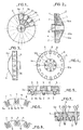
- the collecting blades 1, FIG. 1 are obtained by a stamping tool leaving a small thickness of material 2 between two consecutive blades, Figures 2 and 5.
- Each of the collecting blades 1, is provided on the rear face with three anchoring points 3.3a and 3b in the frustoconical insulating support 4, FIGS. 2 and 5.
- the anchoring point 3, FIG. 1, is provided in the central part of the collecting blades, the anchoring points 3a and 3b are formed towards each of the radial edges, inside the perimeter of said blades and near their part. peripheral.
- the anchor points 3.3a and 3b are obtained by lifting material using a cutting tool.
- the frustoconical insulating support 4 made of molded material, has at its periphery radial projections 5, Figures 2,3 and 4.
- the anchoring means 3a and 3b formed at the periphery of each of the collector blades 1 are embedded respectively in each of the radial projections 5, which are provided in a substantially rectangular shape and of constant thickness so as to provide an effective anchoring of the means 3a and 3b in the molded material constituting said projections 5, FIG. 5.
- the projections 5 of substantially rectangular shape and of constant thickness determine between them cavities 6, FIGS. 4, 5, 6 and 7, into which open notches 7, FIG. 6, for housing the conductors 8 of the armature.
- the cavities 6 have a dimension such that they leave between the conductors 8 and the cavities 6 a space receiving an immobilizing agent for the conductors 8, such as the varnish for impregnating the armature.
- a recess 9 is provided on the sides 5a, 5b of the projections 5, so as to form a housing for the varnish for impregnating the armature so as to improve its behavior during overspeed tests.
- the tubular metal hub 10 (see FIG. 2) has an annular flange 10a (see FIGS. 2 and 4) folded towards the outside diameter of the tubular part at an angle similar to that of the frustoconical part 4a of the insulating support 4.
- the annular flange 10a is made at one end of the metal hub 10 and is arranged towards the end of the insulating support 4 opposite that of the collecting blades 1 (see FIG. 2).
- the annular collar 10a is provided with recesses 10b (see FIGS. 2 and 4) in which the material of the insulating support 4 is housed.
- annular flange 10a can be, if necessary, completely embedded in the insulating support 4, by simple shortening of the tubular part of the hub 10. It is also obvious that the annular flange 10a can be between a certain distance from the rear face of the collecting blades and the end of the frustoconical part of the insulation.
Landscapes
- Motor Or Generator Current Collectors (AREA)
- Manufacture Of Motors, Generators (AREA)
Applications Claiming Priority (2)
| Application Number | Priority Date | Filing Date | Title |
|---|---|---|---|
| FR7914521A FR2458920A1 (fr) | 1979-06-07 | 1979-06-07 | Collecteur frontal pour induit de machine electrique equipant notamment les vehicules automobiles |
| FR7914521 | 1979-06-07 |
Publications (2)
| Publication Number | Publication Date |
|---|---|
| EP0021891A1 EP0021891A1 (fr) | 1981-01-07 |
| EP0021891B1 true EP0021891B1 (fr) | 1983-03-23 |
Family
ID=9226298
Family Applications (1)
| Application Number | Title | Priority Date | Filing Date |
|---|---|---|---|
| EP19800400756 Expired EP0021891B1 (fr) | 1979-06-07 | 1980-05-29 | Collecteur frontal pour machine électrique équipant notamment les véhicules automobiles |
Country Status (4)
| Country | Link |
|---|---|
| EP (1) | EP0021891B1 (show.php) |
| DE (1) | DE3062420D1 (show.php) |
| ES (1) | ES251233Y (show.php) |
| FR (1) | FR2458920A1 (show.php) |
Families Citing this family (3)
| Publication number | Priority date | Publication date | Assignee | Title |
|---|---|---|---|---|
| DE4028420A1 (de) * | 1990-09-07 | 1992-03-12 | Kautt & Bux Kg | Plankommutator und verfahren zu seiner herstellung |
| US5912523A (en) * | 1997-10-03 | 1999-06-15 | Mccord Winn Textron Inc. | Carbon commutator |
| US6359362B1 (en) | 2000-07-31 | 2002-03-19 | Mccord Winn Textron Inc. | Planar commutator segment attachment method and assembly |
Family Cites Families (6)
| Publication number | Priority date | Publication date | Assignee | Title |
|---|---|---|---|---|
| US2127549A (en) * | 1935-05-06 | 1938-08-23 | Roy F Carty | Commutator |
| US2176361A (en) * | 1937-04-15 | 1939-10-17 | Scruggs Loyd | Radial commutator |
| US2791667A (en) * | 1955-07-08 | 1957-05-07 | Gen Electric | Automatic brazing apparatus and method |
| GB1183192A (en) * | 1966-07-29 | 1970-03-04 | Lucas Industries Ltd | Commutators |
| GB1487923A (en) * | 1974-02-16 | 1977-10-05 | Lucas Electrical Ltd | Face commutator |
| ZA775055B (en) * | 1976-09-04 | 1978-07-26 | Lucas Industries Ltd | Method of manufacturing an armature assembly for a dynamo electric machine |
-
1979
- 1979-06-07 FR FR7914521A patent/FR2458920A1/fr active Granted
-
1980
- 1980-05-29 DE DE8080400756T patent/DE3062420D1/de not_active Expired
- 1980-05-29 EP EP19800400756 patent/EP0021891B1/fr not_active Expired
- 1980-06-04 ES ES1980251233U patent/ES251233Y/es not_active Expired
Also Published As
| Publication number | Publication date |
|---|---|
| FR2458920A1 (fr) | 1981-01-02 |
| ES251233Y (es) | 1981-03-16 |
| DE3062420D1 (en) | 1983-04-28 |
| ES251233U (es) | 1980-10-01 |
| FR2458920B1 (show.php) | 1983-04-08 |
| EP0021891A1 (fr) | 1981-01-07 |
Similar Documents
| Publication | Publication Date | Title |
|---|---|---|
| WO2013083407A1 (fr) | Dispositif de guidage d'un ensemble de fils electriques pour rotor de moteur electrique | |
| WO2002050962A1 (fr) | Ensemble porte-balais pour machine electrique | |
| FR2619880A1 (fr) | Butee de debrayage, notamment pour vehicules automobiles | |
| EP0196966B1 (fr) | Butée de débrayage, notamment pour véhicule automobile | |
| EP0349367B1 (fr) | Contacteur électrique pour servomoteur pneumatique de freinage | |
| FR2611244A1 (fr) | Butee de debrayage a piece elastique a action axiale, notamment pour vehicule automobile | |
| EP0021891B1 (fr) | Collecteur frontal pour machine électrique équipant notamment les véhicules automobiles | |
| EP0500442B1 (fr) | Ventilateur pour machines tournantes électriques, notamment pour alternateurs de véhicules automobiles | |
| EP0782241B1 (fr) | Moteur à courant continu avec palier de guidage d'arbre | |
| FR2612349A1 (fr) | Carcasse de bobine de conducteurs electriques, destinee a etre montee sur un noyau rigide, et son procede de fabrication | |
| EP0220981A1 (fr) | Rotor pour machine dynamo-électrique, notamment pour alternateur de véhicules automobiles | |
| FR2573584A1 (fr) | Moteur a induit exterieur | |
| FR2613880A1 (fr) | Rotor a bagues collectrices pour machine dynamo-electrique notamment alternateur de vehicule automobile et procede d'obtention d'un tel rotor | |
| EP3097634B1 (fr) | Dispositif isolant pour collecteur de machine electrique, collecteur et alternateur correspondants | |
| FR2618268A1 (fr) | Collecteur frontal pour machine electrique tournante et procede de fabrication d'un tel collecteur. | |
| FR2533281A2 (fr) | Butee de debrayage, notamment pour vehicule automobile et son procede de montage | |
| FR2532789A1 (fr) | Collecteur de machine electique tournante, et son procede de fabrication | |
| EP1603760B1 (fr) | Dispositif de montage d'une structure rotative sur un axe | |
| WO2003055040A1 (fr) | 'machine electrique tournante comportant des moyens de positionnement angulaire de la carcasse par rapport à la plque porte-charbon' | |
| FR2623024A1 (fr) | Connecteur auto-denudant pour conducteur electrique isole | |
| FR2640049A1 (fr) | Capteur electromagnetique a reluctance variable et procede d'assemblage d'un tel capteur | |
| EP0086692B1 (fr) | Arbre support de distributeur d'allumage | |
| FR2669980A1 (fr) | Butee de debrayage a rondelle elastique externe, notamment pour vehicules automobiles. | |
| EP0605307B1 (fr) | Bride pour moteur électrique et son application au montage notamment d'une pompe | |
| FR2779882A1 (fr) | Dispositif de freinage d'un moteur, moteur muni du dispositif et appareil muni de ceux-ci |
Legal Events
| Date | Code | Title | Description |
|---|---|---|---|
| PUAI | Public reference made under article 153(3) epc to a published international application that has entered the european phase |
Free format text: ORIGINAL CODE: 0009012 |
|
| AK | Designated contracting states |
Designated state(s): DE GB IT |
|
| 17P | Request for examination filed |
Effective date: 19801216 |
|
| ITF | It: translation for a ep patent filed | ||
| GRAA | (expected) grant |
Free format text: ORIGINAL CODE: 0009210 |
|
| AK | Designated contracting states |
Designated state(s): DE GB IT |
|
| REF | Corresponds to: |
Ref document number: 3062420 Country of ref document: DE Date of ref document: 19830428 |
|
| PGFP | Annual fee paid to national office [announced via postgrant information from national office to epo] |
Ref country code: DE Payment date: 19840525 Year of fee payment: 5 |
|
| PG25 | Lapsed in a contracting state [announced via postgrant information from national office to epo] |
Ref country code: GB Effective date: 19890529 |
|
| GBPC | Gb: european patent ceased through non-payment of renewal fee | ||
| PG25 | Lapsed in a contracting state [announced via postgrant information from national office to epo] |
Ref country code: DE Effective date: 19900201 |
|
| PLBE | No opposition filed within time limit |
Free format text: ORIGINAL CODE: 0009261 |
|
| STAA | Information on the status of an ep patent application or granted ep patent |
Free format text: STATUS: NO OPPOSITION FILED WITHIN TIME LIMIT |