EP0021480B1 - Hubwagen mit Eigenantrieb und Längsverschiebbarkeit der Lastaufnahme - Google Patents
Hubwagen mit Eigenantrieb und Längsverschiebbarkeit der Lastaufnahme Download PDFInfo
- Publication number
- EP0021480B1 EP0021480B1 EP80200505A EP80200505A EP0021480B1 EP 0021480 B1 EP0021480 B1 EP 0021480B1 EP 80200505 A EP80200505 A EP 80200505A EP 80200505 A EP80200505 A EP 80200505A EP 0021480 B1 EP0021480 B1 EP 0021480B1
- Authority
- EP
- European Patent Office
- Prior art keywords
- truck
- load
- carriage
- self
- forks
- Prior art date
- Legal status (The legal status is an assumption and is not a legal conclusion. Google has not performed a legal analysis and makes no representation as to the accuracy of the status listed.)
- Expired
Links
- 239000004606 Fillers/Extenders Substances 0.000 description 1
- 239000007787 solid Substances 0.000 description 1
Images


Classifications
-
- H—ELECTRICITY
- H01—ELECTRIC ELEMENTS
- H01L—SEMICONDUCTOR DEVICES NOT COVERED BY CLASS H10
- H01L23/00—Details of semiconductor or other solid state devices
- H01L23/52—Arrangements for conducting electric current within the device in operation from one component to another, i.e. interconnections, e.g. wires, lead frames
- H01L23/522—Arrangements for conducting electric current within the device in operation from one component to another, i.e. interconnections, e.g. wires, lead frames including external interconnections consisting of a multilayer structure of conductive and insulating layers inseparably formed on the semiconductor body
- H01L23/5226—Via connections in a multilevel interconnection structure
-
- B—PERFORMING OPERATIONS; TRANSPORTING
- B66—HOISTING; LIFTING; HAULING
- B66F—HOISTING, LIFTING, HAULING OR PUSHING, NOT OTHERWISE PROVIDED FOR, e.g. DEVICES WHICH APPLY A LIFTING OR PUSHING FORCE DIRECTLY TO THE SURFACE OF A LOAD
- B66F9/00—Devices for lifting or lowering bulky or heavy goods for loading or unloading purposes
- B66F9/06—Devices for lifting or lowering bulky or heavy goods for loading or unloading purposes movable, with their loads, on wheels or the like, e.g. fork-lift trucks
- B66F9/065—Devices for lifting or lowering bulky or heavy goods for loading or unloading purposes movable, with their loads, on wheels or the like, e.g. fork-lift trucks non-masted
-
- H—ELECTRICITY
- H01—ELECTRIC ELEMENTS
- H01L—SEMICONDUCTOR DEVICES NOT COVERED BY CLASS H10
- H01L2924/00—Indexing scheme for arrangements or methods for connecting or disconnecting semiconductor or solid-state bodies as covered by H01L24/00
- H01L2924/0001—Technical content checked by a classifier
- H01L2924/0002—Not covered by any one of groups H01L24/00, H01L24/00 and H01L2224/00
Definitions
- the forks are mounted on a pantograph extender fixed to telescopic lifting cylinders extending vertically from the front of the self-propelled truck.
- a pantograph extender fixed to telescopic lifting cylinders extending vertically from the front of the self-propelled truck.
- Such a truck has the drawback of a low-rigidity supporting structure, and of supporting the load in a completely jutting disposition beyond its front wheels. This substantially limits the truck capacity and its degree of safety.
- the forward projecting traverse movement is obtained by complicated articulated parallelogram linkages which, for correct positioning of the load, always require a combination of two movements which are very difficult for the operator, the trajectory of the load movement never being horizontal and varying as a function of the angle between the parallelogram sides.
- a lift-apparatus of this type is for example described in the patent DE-A-2 504 185.
- An examination of the specification and drawings of said patent shows clearly that the horizontal translation of the apparatus can be achieved only by moving the truck on the terrain, with all the risks that this involves if the terrain is uneven, or, with the truck stationary, by causing the articulated parallelogram to perform a combined rotary-cum-translation movement. This because the truck and the lifting apparatus are operatively interconnected.
- the operating cab of the machine is laterally swept by the arms of the parallelogram, with the risk of "guillotining" the operator.
- truck which comprises telescopic arms with a fixed hinging point, a hydraulic parallelogram and a central driving position.
- the load is provided with a horizontal trajectory by a combination of two movements which require great attention by the operator, who if he makes a mistake can risk inclining the forks, with consequent damage to the load and dangerous tilting thereof.
- a further truck of traditional type comprises a central telescopic arm and a hydraulic parallelogram. It has the same drawbacks as the latter type of said truck, and furthermore the operator's visibility is rather poor because of the central arrangement of the telescopic arm.
- a type of truck comprising a horizontally traversing central trellis-type arm and a mechanical parallelogram.
- this has the drawback of a very wide chassis and a consequent lack of operator visibility, there again being the possibility of inclining the forks and tilting the load if mistakes are made in operation.
- the object of the present invention is to provide a translation lift apparatus, e.g. a fork lift truck, fitted with a longitudinal horizontal traverser and of such a structure as to obviate or at least minimise the drawbacks of known trucks as briefly described heretofore.
- a translation lift apparatus e.g. a fork lift truck
- a translation lift-apparatus comprising a truck on which is mounted a lifting apparatus consisting of a means for taking up the load actuated by an articulated parallelogram system translatable on horizontal guides and operated by oleodynamic cylinders, characterized by the fact that said lifting apparatus is provided with a carriage (16) translatable on horizontal guides (13) provided at the top of a central operating cab (11) having a bearing structure which supports said lifting apparatus, and by the fact that said oleodynamic cylinders (20, 26) all act between said carriage (16) and said articulated parallelogram system.
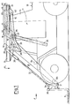
- the fork lift truck according to the invention comprises a vehicle 10 with a central guide cab 11, on the top of which is mounted the fork lift apparatus 9.
- Said apparatus comprises a horizontal traverser indicated overall by 12, which is made to slide on a pair of lateral guides 13 fixed to the top of the load-bearing structure 14 of the driving cab 11 and connected together by a cross-member 15.
- the traverser comprises a carriage 16 formed from a pair of longitudinal box beams 17 which are connected together by a pair of terminal cross-members 18.
- the carriage 16 is mounted on the guides 13 by wheels 19 connected to the beams 17.
- the traversing movement of the carriage 16 is controlled by a hydraulic cylinder 20 pivoted to the cross-member 15 so as to rotate about the axis 21, and its rod 22 is hinged to the front cross-member 18 of said carriage.
- Said arms 23 rotate about the pivots 25 under the control of a pair of hydraulic cylinders 26, which are hinged to the beams 17 about 27, and have their rods 28 pivoted at 29 to the arms 23.
- a plate 30 carrying the forks 9 is connected to the free end of the arms 23.
- the plate 30 can be inclined through a small angle about the pivots 31.
- the movement of the plate 30 is controlled by a pair of hydraulic cylinders 32, the rod 33 of which is pivoted at 34 to said plate 30.
- Each cylinder 32 is pivoted in its turn at 35 to one end of an angle lever 36, which is pivoted at an intermediate point 37 to the relative arm 23. At its end distant from the end 35, the lever 36 is pivoted at 38 to one end of a rod 39, the other end of which is pivoted at 40 to the beam 17.
- a double articulated parallelogram is thus formed.
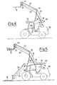
- FIGURE 1 shows the fork lift truck in its rest position, with the forks on the ground and the carriage 16 completely withdrawn. Any load on the ground can thus be taken by the forks, raised into the position of FIGURE 4 and then moved horizontally with a forward traversing movement into the position of FIGURE 5, to be then deposited on the required working surface.
- the forks which always move parallel to themselves, can also be slightly inclined upwards so as to operate under conditions of maximum safety, without any danger of the load falling.
Landscapes
- Engineering & Computer Science (AREA)
- Structural Engineering (AREA)
- Transportation (AREA)
- General Physics & Mathematics (AREA)
- Condensed Matter Physics & Semiconductors (AREA)
- Computer Hardware Design (AREA)
- Microelectronics & Electronic Packaging (AREA)
- Power Engineering (AREA)
- Civil Engineering (AREA)
- Physics & Mathematics (AREA)
- Life Sciences & Earth Sciences (AREA)
- Geology (AREA)
- Mechanical Engineering (AREA)
- Forklifts And Lifting Vehicles (AREA)
Claims (1)
- Ein bewegliches Hebegerät mit einem Fahrgestell, auf dem eine Hebevorrichtung angeordnet ist, die aus einem, mittels eines auf waagrechten Führungen (13) verschiebbaren, durch oeldynamische Zylinder (20, 26) gesteuerten Gelenkparallelogrammsystems betätigten Lastaufnahmemittel besteht, dadurch gekennzeichnet, dass die besagte Hebevorrichtung mit einem auf den waagrechten Führungen (13) verschiebbaren Wagen (16) versehen ist, welche Führungen oben auf der mittleren Steuerkabine (11) angebracht sind, die einen die genannte Hebevorrichtung tragenden Aufbau besitzt, sowie dadurch, dass die genannten öldynamischen Zylinder (20, 26) alle zwischen dem genannten Wagen (16) und dem genannten Gelenkparallelogrammsystem wirken.
Applications Claiming Priority (2)
| Application Number | Priority Date | Filing Date | Title |
|---|---|---|---|
| IT42907/79A IT1166206B (it) | 1979-06-12 | 1979-06-12 | Sollevatore semovente a forche con dispositivo a traslazione orizzontale atto ad assicurare: 1) presa del carico da fermo, 2) abbandono del carico da fermo, 3) applicazione di una rampa ausiliaria senza possibilita' di ribaltamento della stessa oltre l'inclinazione voluta, 4) possibilita' di uso di pala caricatrice ed altri attrezzi |
| IT4290779 | 1979-06-12 |
Publications (2)
| Publication Number | Publication Date |
|---|---|
| EP0021480A1 EP0021480A1 (de) | 1981-01-07 |
| EP0021480B1 true EP0021480B1 (de) | 1983-06-08 |
Family
ID=11254590
Family Applications (1)
| Application Number | Title | Priority Date | Filing Date |
|---|---|---|---|
| EP80200505A Expired EP0021480B1 (de) | 1979-06-12 | 1980-05-28 | Hubwagen mit Eigenantrieb und Längsverschiebbarkeit der Lastaufnahme |
Country Status (4)
| Country | Link |
|---|---|
| EP (1) | EP0021480B1 (de) |
| DE (1) | DE3063668D1 (de) |
| FR (1) | FR2458508A1 (de) |
| IT (1) | IT1166206B (de) |
Families Citing this family (1)
| Publication number | Priority date | Publication date | Assignee | Title |
|---|---|---|---|---|
| US5709523A (en) * | 1995-06-07 | 1998-01-20 | Ware; Emmet P. | Material handling lift |
Family Cites Families (9)
| Publication number | Priority date | Publication date | Assignee | Title |
|---|---|---|---|---|
| CH299295A (de) * | 1952-03-29 | 1954-06-15 | Schneider Hans | Mechanische Grab- und Ladevorrichtung. |
| US3198359A (en) * | 1963-01-29 | 1965-08-03 | Le Grand H Lull | Reaching type loader |
| US3257014A (en) * | 1964-09-14 | 1966-06-21 | Sturdivant Ag | Mobile loader |
| US3567053A (en) * | 1969-04-04 | 1971-03-02 | Harry E Willock | Load hoisting truck |
| FR2085264B1 (de) * | 1970-04-02 | 1975-02-21 | Potain Sa | |
| US4034874A (en) * | 1973-10-19 | 1977-07-12 | International Harvester Company | Hose supporting linkage |
| AT327792B (de) * | 1974-02-04 | 1976-02-25 | Schoberl & Soehne Joh | Fahrbares ladegerat |
| US3967744A (en) * | 1975-02-18 | 1976-07-06 | Clark Equipment Company | Extensible reach load lifting mechanism |
| US4147263A (en) * | 1977-01-06 | 1979-04-03 | Lull Engineering Company, Inc. | High lift loader with extended transfer |
-
1979
- 1979-06-12 IT IT42907/79A patent/IT1166206B/it active
-
1980
- 1980-04-25 FR FR8009390A patent/FR2458508A1/fr active Granted
- 1980-05-28 DE DE8080200505T patent/DE3063668D1/de not_active Expired
- 1980-05-28 EP EP80200505A patent/EP0021480B1/de not_active Expired
Also Published As
| Publication number | Publication date |
|---|---|
| FR2458508B1 (de) | 1984-06-29 |
| EP0021480A1 (de) | 1981-01-07 |
| DE3063668D1 (en) | 1983-07-14 |
| IT7942907A0 (it) | 1979-06-12 |
| IT1166206B (it) | 1987-04-29 |
| FR2458508A1 (fr) | 1981-01-02 |
Similar Documents
| Publication | Publication Date | Title |
|---|---|---|
| US4065012A (en) | Low lift truck | |
| US7419023B2 (en) | Transfer apparatus | |
| EP2490980B1 (de) | Gabelstabpler, im besonderen zum heben und stapeln von booten | |
| US6571913B2 (en) | Multipurpose machine | |
| US4457403A (en) | Self-propelled elevating work platform | |
| US6378652B1 (en) | Lateral jib for vertical mast mobile elevating work platform | |
| US4995774A (en) | Side-loading fork lift vehicle | |
| US6796762B2 (en) | Boom and linkage mechanism for skid-steer loader | |
| US3223251A (en) | Displaceable jack for automotive vehicles | |
| US3966070A (en) | Mechanism for loader bucket or forklift mast on a material handling vehicle | |
| US6227569B1 (en) | Stabilizer mechanical support linkage | |
| JP3133793B2 (ja) | リフト・ローダブーム装置およびリフト・ローダブーム装置を用いた作業具移動方法 | |
| US4067245A (en) | Lever transmission particularly for lifting means | |
| EP0021480B1 (de) | Hubwagen mit Eigenantrieb und Längsverschiebbarkeit der Lastaufnahme | |
| US3490633A (en) | Assembly for laterally shifting and pivoting a mast of a lift truck | |
| US4431083A (en) | Apparatus for lifting a member using parallelogram mounted links | |
| EP0205265B1 (de) | Fahrzeug für Arbeit in der Höhe | |
| WO1988006567A1 (en) | Device in a fork truck | |
| WO1996026152A1 (en) | Auto body repair apparatus | |
| EP0286300A1 (de) | Ausleger für Arbeitshebebühne | |
| EP0641708A1 (de) | Fahrzeug | |
| US3522896A (en) | Lift truck | |
| FI65974B (fi) | Laenksystem foer lastlyftanordning | |
| GB2084113A (en) | Rack-feeding truck | |
| US20210179405A1 (en) | Operating machine with improved stabilisers |
Legal Events
| Date | Code | Title | Description |
|---|---|---|---|
| PUAI | Public reference made under article 153(3) epc to a published international application that has entered the european phase |
Free format text: ORIGINAL CODE: 0009012 |
|
| AK | Designated contracting states |
Designated state(s): DE FR GB IT SE |
|
| 17P | Request for examination filed |
Effective date: 19810617 |
|
| ITF | It: translation for a ep patent filed |
Owner name: BARZANO' E ZANARDO MILANO S.P.A. |
|
| GRAA | (expected) grant |
Free format text: ORIGINAL CODE: 0009210 |
|
| AK | Designated contracting states |
Designated state(s): DE FR GB IT SE |
|
| PG25 | Lapsed in a contracting state [announced via postgrant information from national office to epo] |
Ref country code: SE Effective date: 19830608 |
|
| REF | Corresponds to: |
Ref document number: 3063668 Country of ref document: DE Date of ref document: 19830714 |
|
| EL | Fr: translation of claims filed | ||
| PLBE | No opposition filed within time limit |
Free format text: ORIGINAL CODE: 0009261 |
|
| STAA | Information on the status of an ep patent application or granted ep patent |
Free format text: STATUS: NO OPPOSITION FILED WITHIN TIME LIMIT |
|
| PGFP | Annual fee paid to national office [announced via postgrant information from national office to epo] |
Ref country code: FR Payment date: 19840517 Year of fee payment: 5 |
|
| PGFP | Annual fee paid to national office [announced via postgrant information from national office to epo] |
Ref country code: DE Payment date: 19840530 Year of fee payment: 5 |
|
| 26N | No opposition filed | ||
| GBPC | Gb: european patent ceased through non-payment of renewal fee | ||
| PG25 | Lapsed in a contracting state [announced via postgrant information from national office to epo] |
Ref country code: FR Free format text: LAPSE BECAUSE OF NON-PAYMENT OF DUE FEES Effective date: 19860131 |
|
| PG25 | Lapsed in a contracting state [announced via postgrant information from national office to epo] |
Ref country code: DE Effective date: 19860201 |
|
| REG | Reference to a national code |
Ref country code: FR Ref legal event code: ST |
|
| PG25 | Lapsed in a contracting state [announced via postgrant information from national office to epo] |
Ref country code: GB Effective date: 19881118 |