EP0021394B1 - Interelectrode impedance measuring apparatus for electrocardiography - Google Patents
Interelectrode impedance measuring apparatus for electrocardiography Download PDFInfo
- Publication number
- EP0021394B1 EP0021394B1 EP80103535A EP80103535A EP0021394B1 EP 0021394 B1 EP0021394 B1 EP 0021394B1 EP 80103535 A EP80103535 A EP 80103535A EP 80103535 A EP80103535 A EP 80103535A EP 0021394 B1 EP0021394 B1 EP 0021394B1
- Authority
- EP
- European Patent Office
- Prior art keywords
- ekg
- value
- impedance
- amplitude
- electrodes
- Prior art date
- Legal status (The legal status is an assumption and is not a legal conclusion. Google has not performed a legal analysis and makes no representation as to the accuracy of the status listed.)
- Expired
Links
Images


Classifications
-
- A—HUMAN NECESSITIES
- A61—MEDICAL OR VETERINARY SCIENCE; HYGIENE
- A61B—DIAGNOSIS; SURGERY; IDENTIFICATION
- A61B5/00—Measuring for diagnostic purposes; Identification of persons
- A61B5/24—Detecting, measuring or recording bioelectric or biomagnetic signals of the body or parts thereof
- A61B5/25—Bioelectric electrodes therefor
- A61B5/276—Protection against electrode failure
-
- A—HUMAN NECESSITIES
- A61—MEDICAL OR VETERINARY SCIENCE; HYGIENE
- A61B—DIAGNOSIS; SURGERY; IDENTIFICATION
- A61B5/00—Measuring for diagnostic purposes; Identification of persons
- A61B5/24—Detecting, measuring or recording bioelectric or biomagnetic signals of the body or parts thereof
- A61B5/30—Input circuits therefor
- A61B5/307—Input circuits therefor specially adapted for particular uses
- A61B5/308—Input circuits therefor specially adapted for particular uses for electrocardiography [ECG]
-
- G—PHYSICS
- G01—MEASURING; TESTING
- G01R—MEASURING ELECTRIC VARIABLES; MEASURING MAGNETIC VARIABLES
- G01R27/00—Arrangements for measuring resistance, reactance, impedance, or electric characteristics derived therefrom
- G01R27/02—Measuring real or complex resistance, reactance, impedance, or other two-pole characteristics derived therefrom, e.g. time constant
- G01R27/16—Measuring impedance of element or network through which a current is passing from another source, e.g. cable, power line
Definitions
- This invention relates to an inter-electrode impedance measuring apparatus for measuring or monitoring the impedance of EKG electrodes positioned to pick up EKG signals from a patient.
- EKG electrocardiographic
- the most important requirement for high quality EKG signals is that the EKG electrode impedances must be sufficiently low.
- the cause of a high EKG electrode impedance is usually a high contact impedance between one or more electrodes and the patient's skin.
- the skin contact impedance may be high because of improper installation of the electrode or perhaps because the electrode has become partly or fully detached from the skin surface.
- Another possible cause of unusually high electrode impedance might be broadly called lead failure and refers to any high impedance along the electrical path from the electrode to the first amplifying stage of the EKG apparatus.
- the electrode impedance is effectively placed in a feedback loop of an oscillator circuit.
- the oscillator changes state (it either begins oscillating or stops oscillating) and the change of state is detected and indicated to an operator in some way.
- the frequency of oscillation is high (5 kilohertz) and in the other (U.S. patent 4,027,633) it is low (40 hertz).
- Direct monitoring of electrode impedance is also taught by DE-B-2104850.
- serially connected impedances of equal values are connected across the inputs of a brain wave measuring apparatus and a source of ac check signals is provided to be connectable to the juncture between the impedances. While the electrodes are in position to pick up signals from the patient's body, the source of ac check signals may be connected to said juncture between the impedances to check for the occurrence of distinct alterations of the electrode contact resistances.
- impedance changes as a function of frequency. It follows that the magnitude of the impedance sensed by means of oscillators or other sources of ac check signals is generally dependent upon the frequencies used. The magnitude of this impedance, which has been sensed at specific frequencies, may or may not be closely related to the effective (or average or maximum) impedance experienced by an EKG signal, which is a peculiar mix of frequency components between about 0.05 hertz and 100 hertz.
- the oscillators or the source of ac check signals adds a signal to the true biological waveform. Since this added signal has a known frequency, it can be filtered from the combined waveform, but not without also filtering the same frequency component from the true biological signal. If the frequency of the oscillator or of the source of ac check signals is not within the range of frequency components of the biological signal, this causes no distortion of the true biological waveform, but then the electrode impedance is being measured at a frequency which is outside the range of frequencies at which the electrode is intended to be used.
- Advantages offered by the invention are mainly that it can be implemented in any EKG apparatus, including those containing a digital computer for EKG analysis, with a minimum of additional components; that the EKG electrode impedance is measured with the same mix of frequency components normally encountered by EKG electrodes during collection of EKG waveforms; that the EKG electrode impedance can be measured without distoring the collected EKG waveforms in any way and that no external voltage is applied to the patient's body during measurement of EKG electrode impedance.
- the invention provides an inter-electrode impedance measuring apparatus for measuring the inter-electrode impedance Z E between two EKG electrodes while said EKG electrodes are in position to pick up EKG signals from a subject including means for measuring the amplitude of EKG signals picked up by said EKG electrodes, characterized in that provision is made of an impedance element Z T and means for temporarily connecting said impedance element Z T across said EKG electrodes, said measuring means measuring both the amplitude A u of an EKG signal picked up by said EKG electrodes when said impedance element Z T is not connected across said EKG electrodes and the amplitude A L of an EKG signal picked up by said EKG electrodes when said impedance element Z T is connected across said EKG electrodes, the inter-electrode impedance Z E being related to Z T , A u and A L at least to an approximation by the formula
- Fig. 1 illustrates the principles of the present invention through a manually operated embodiment thereof.
- An EKG sensing electrode 10 and a reference electrode 11 are attached to an arm and leg respectively of patient 12. It should be understood that in practice more than two electrodes are ordinarily attached in order to be able to record EKG waveforms at several different locations simultaneously. Although the invention, is described with respect to only two electrodes and a single EKG waveform taken therebetween, it should be apparent that the invention may be extended for use with any number of electrodes and any number of waveforms.
- the voltage signals at electrodes 10, 11 1 are conveyed by conductors 14, 16 to differential amplifier 18. Differential amplifier 18 then presents an EKG waveform to a displaying apparatus 20, such as a strip chart recorder. This EKG waveform is the time variation of the difference between the potential at electrodes 10 and 11.
- test impedance Z T is connected in series with a normally open pushbutton switch 22 between conductors 14 and 16 in order to allow test impedance Z T to be temporarily inserted as a shorting impedance between conductors 14 and 16 through depression of pushbutton 22.
- Test impedance Z r is variable as shown so that the amount of loading placed upon the electrodes during the shorting test may be varied if desired. In one mode of operation the test impedance is varied until a loading effect is noticed upon EKG signal amplitude.
- the value of the inter-electrode impedance may then be derived from the value of the test impedance which produced a loading effect in accordance with the formula where Z E is the inter-electrode impedance, A u is the unloaded amplitude of the EKG signal and A L is the loaded amplitude of the EKG signal.
- the input impedance of differential amplifier 18 should be as high as possible. In order for the above-disclosed formula to be accurate, the input impedance of the differential amplifier must be so much higher than Z T that the loading effect produced by amplifier 18 may be neglected. It will be apparent that if amplifier 18 does have a significant effect, Ohm's Law can be used to derive a more complex formula which takes into account the value of the input impedance of amplifier 18. This extension of the invention is considered apparent and it does not depart from the spirit of this invention, which in its most general form is the idea of loading the EKG electrodes with two different loads and determining from the reduction in EKG signal amplitude the inter-electrode impedance value.
- the value of the test impedance Z T is selected to have a predetermined value approximately the same as the maximum permitted inter-electrode impedance between electrodes 10 and 11.
- the value of impedance Z T should be the same as the maximum permitted inter-electrode impedance, but it may be within a range of perhaps an order of magnitude or more. on each side of this value. Since the value of the test impedance Z T is known and the maximum permitted value of the inter-electrode impedance Z E is predetermined, the above formula will define a ratio AjAL' The EKG amplitude ratio may then be monitored. When the amplitude ratio goes above this defined ratio, the inter-electrode impedance is higher than the predetermined maximum permitted value.
- an operator starts recorder 20 and records at least one heart beat on the recorder 20 with the pushbutton not depressed and then depresses pushbutton 22 during at least one additional heart beat (or vice versa).
- the amplitudes of the EKG waveforms recorded under these two conditions are compared. If the EKG waveform taken while the pushbutton is depressed is half the amplitude of the EKG waveform taken while the pushbutton is not depressed, then the inter electrode impedance is equal to Z T , neglecting any loading effect of amplifier 18.
- Fig. 2 illustrates the QRS complexes of three EKG waveforms superimposed for convenience.
- Waveform 24 was taken while pushbutton 22 was not depressed.
- Line 26 represents half the amplitude of the large amplitude positive wave (called the R wave).
- Waveforms 28 and 30 are two possible EKG waveforms which might be obtained from the same patient immediately prior to or following the recording of waveform 24 upon depressing pushbutton 22.
- the R wave of waveform 28 is above line 26, which means that the EKG electrode impedance was lower than Z T when this waveform was recorded.
- the R wave of waveform 30 is below line 26, which means that the EKG electrode impedance was higher than Z r when this waveform was recorded.
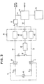
- Fig. 3 illustrates an automated embodiment of the invention.
- An equivalent circuit is represented here in place of the patient.
- Voltage source 15 represents the source of EKG signals.
- Z E is the total inter-electrode impedance which is represented here as two resistors, each of value Z E /2 and each connected between voltage source 15 on one side and sensing electrode 10 and reference electrode 11 on the other, respectively.
- a switch 32 In place of the pushbutton 22 is a switch 32, the position of which is controlled by actuator 34.
- EKG signals from the patient 12 as well as signals which control actuator 34 pass through a patient isolator circuit 36 which comprises electrical isolators 38, 40 and 42. These isolators are preferably optical isolators.
- signal analysis logic 44 automatically causes switch 32 to be closed and opened in a controlled manner.
- Switch 32 may be alternately opened and closed during successive heart beats or in accordance with any arbitrary schedule or plan.
- logic 44 compares the amplitudes of the EKG waveforms obtained under alternate positions of switch 32. When the loaded EKG waveform (switch 32 closed) has an amplitude lower than a predetermined percentage of the unloaded EKG waveform (switch 32 open), logic 44 causes an indication thereof to be displayed by indicator 46.
- Fig. 4 illustrates in further detail how logic 44 might be constructed.
- Bandpass filter 48 removes from the signal received from the output of amplifier 18 those frequency components which are outside the range of frequency components of an EKG signal. The function of this filter is to eliminate signal components which are not part of the true EKG waveform but which could still affect subsequent signal level comparisons.
- the bandpass filter eliminates D.C. drift and removes high frequency artifact spikes, for example.
- Peak follower circuit 50 The output of the bandpass filter is presented to a peak follower circuit 50, the function of which is to monitor the input signal thereto and hold (or store) the highest input amplitude value.
- Peak follower 50 is reset via line 52 by a sequence control circuit 54.
- Sequence control circuit 54 also controls switch 32 (Fig. 3) via line 56.
- switch 32 Fig. 3
- peak follower 50 is also ordinarily reset by sequence control 54 so that it can then begin to find the maximum amplitude of the EKG signal with the switch 32 in the new position.
- the peak follower should be finding the highest R-wave. In the presence of artifacts, a circuit which reliably does this is complex. However, there already are prior art circuits which do this and EKG analysis by digital computer inherently requires that the R-waves be located. Since this function is already performed by digital computer analysis programs, it is preferred that all of the data processing functions of this invention be implemented on a digital computer.
- the average amplitude of R-waves could also be readily computed by such a digital computer and computed average amplitude values used in place of maximum amplitude values. By using average values of R-wave amplitude the normal variations in such amplitude would also be expected to cause less of an error in the derived value of Z E .
- a reset signal on line 58 from sequence control 54 causes sample and hold circuit 60 to receive via line 62 the highest amplitude value collected by peak follower 50 since the last reset thereof. This represents the amplitude of the unloaded EKG signal during the open position of switch 32.
- peak follower 50 collects the highest amplitude value of the EKG signal during the loaded condition and presents it to comparator 64 via amplifier 66.
- the gain of amplifier 66 is adjusted to exactly compensate for the maximum permitted EKG amplitude reduction during the loading test. For example, if the maximum permitted reduction in amplitude is one-half, corresponding to an electrode impedance Z E equal to the test impedance Z T , then the gain of amplifier 66 will be two.
- the output of amplifier 66 presented via line 68 to comparator 64 will be greater than the value stored by the sample and hold circuit 60 (representing the amplitude of the unloaded EKG signal) which is simultaneously presented to comparator 64 via line 70. If the loaded EKG signal amplitude is less than the predetermined percentage of the unloaded EKG signal amplitude, the reverse will be true ⁇ the signal on line 70 will be larger than the signal on line 68.
- sequence control 54 enables (via line 72) indicator 46 to display the results of the amplitude comparison.
Landscapes
- Health & Medical Sciences (AREA)
- Life Sciences & Earth Sciences (AREA)
- Physics & Mathematics (AREA)
- Molecular Biology (AREA)
- Animal Behavior & Ethology (AREA)
- Pathology (AREA)
- Engineering & Computer Science (AREA)
- Biomedical Technology (AREA)
- Heart & Thoracic Surgery (AREA)
- Medical Informatics (AREA)
- Veterinary Medicine (AREA)
- Surgery (AREA)
- Biophysics (AREA)
- General Health & Medical Sciences (AREA)
- Public Health (AREA)
- Cardiology (AREA)
- General Physics & Mathematics (AREA)
- Measurement And Recording Of Electrical Phenomena And Electrical Characteristics Of The Living Body (AREA)
- Testing Of Short-Circuits, Discontinuities, Leakage, Or Incorrect Line Connections (AREA)
- Measurement Of Resistance Or Impedance (AREA)
Description
- This invention relates to an inter-electrode impedance measuring apparatus for measuring or monitoring the impedance of EKG electrodes positioned to pick up EKG signals from a patient.
- It is particularly important for correct and accurate operation of any electrocardiographic (EKG) apparatus, whether it is monitoring patient condition or collecting electrocardiogram signals, that the detected heart beat signals must be of sufficient quality. The most important requirement for high quality EKG signals is that the EKG electrode impedances must be sufficiently low. The cause of a high EKG electrode impedance is usually a high contact impedance between one or more electrodes and the patient's skin. The skin contact impedance may be high because of improper installation of the electrode or perhaps because the electrode has become partly or fully detached from the skin surface. Another possible cause of unusually high electrode impedance might be broadly called lead failure and refers to any high impedance along the electrical path from the electrode to the first amplifying stage of the EKG apparatus. Electrical connectors can produce this type of high electrode impedance. Whatever the source, a high electrode impedance results in receiving signals at the first amplifying stage which are not true or reliable representations of heart activity. It should be readily apparent that detection of EKG electrode impedances which are to high is valuable in any EKG apparatus and is particularly important in situations where the EKG signals are being merely collected and are not being immediately displayed, plotted, processed or analyzed.
- In most prior art EKG apparatus, the input amplification stages have very high input impedance in order to make the EKG apparatus as insensitive as possible to variations in electrode impedance. Other attempts have been made to further reduce sensitivity to electrode impedance variations. For example, in U.S. patent 3,500,823 the EKG electrode is made purely capacitive so that there will be no sensitivity at all with respect to variations in ohmic contact resistance. This does not, however, remove sensitivity to other sources of ohmic lead resistance variation nor does it consider at all that total electrode impedance still varies with changes in the effective capacitance thereof. Direct monitoring of electrode impedance is preferable and is taught, for example, in U.S. Patents 3,495,584 and 4,027,663. In these patents the electrode impedance is effectively placed in a feedback loop of an oscillator circuit. When the electrode impedance gets above a predetermined threshold, the oscillator changes state (it either begins oscillating or stops oscillating) and the change of state is detected and indicated to an operator in some way. In one teaching (U.S. patent 3,495,584) the frequency of oscillation is high (5 kilohertz) and in the other (U.S. patent 4,027,633) it is low (40 hertz).
- Direct monitoring of electrode impedance is also taught by DE-B-2104850. In this patent, serially connected impedances of equal values are connected across the inputs of a brain wave measuring apparatus and a source of ac check signals is provided to be connectable to the juncture between the impedances. While the electrodes are in position to pick up signals from the patient's body, the source of ac check signals may be connected to said juncture between the impedances to check for the occurrence of distinct alterations of the electrode contact resistances.
- In general, impedance changes as a function of frequency. It follows that the magnitude of the impedance sensed by means of oscillators or other sources of ac check signals is generally dependent upon the frequencies used. The magnitude of this impedance, which has been sensed at specific frequencies, may or may not be closely related to the effective (or average or maximum) impedance experienced by an EKG signal, which is a peculiar mix of frequency components between about 0.05 hertz and 100 hertz.
- Another disadvantage of these prior art impedance monitors is that the patient must necessarily be connected to the oscillator circuit or to other sources of ac check signals, which means that some voltage, however small, must necessarily be applied to the patient. The oscillator or ac check signal waveform is actually applied to the patient. This is contrary to the present-day requirement that the patient be totally isolated as much as possible from any electrical equipment. Deliberate application of voltage to a patient is always to be avoided if possible.
- Still another disadvantage of such impedance monitors is that the oscillators or the source of ac check signals adds a signal to the true biological waveform. Since this added signal has a known frequency, it can be filtered from the combined waveform, but not without also filtering the same frequency component from the true biological signal. If the frequency of the oscillator or of the source of ac check signals is not within the range of frequency components of the biological signal, this causes no distortion of the true biological waveform, but then the electrode impedance is being measured at a frequency which is outside the range of frequencies at which the electrode is intended to be used.
- Advantages offered by the invention are mainly that it can be implemented in any EKG apparatus, including those containing a digital computer for EKG analysis, with a minimum of additional components; that the EKG electrode impedance is measured with the same mix of frequency components normally encountered by EKG electrodes during collection of EKG waveforms; that the EKG electrode impedance can be measured without distoring the collected EKG waveforms in any way and that no external voltage is applied to the patient's body during measurement of EKG electrode impedance.
- The invention provides an inter-electrode impedance measuring apparatus for measuring the inter-electrode impedance ZE between two EKG electrodes while said EKG electrodes are in position to pick up EKG signals from a subject including means for measuring the amplitude of EKG signals picked up by said EKG electrodes, characterized in that provision is made of an impedance element ZT and means for temporarily connecting said impedance element ZT across said EKG electrodes, said measuring means measuring both the amplitude Au of an EKG signal picked up by said EKG electrodes when said impedance element ZT is not connected across said EKG electrodes and the amplitude AL of an EKG signal picked up by said EKG electrodes when said impedance element ZT is connected across said EKG electrodes, the inter-electrode impedance ZE being related to ZT, Au and AL at least to an approximation by the formula

- In the accompanying drawings:
- Fig. 1 schematically illustrates a manually operated simplified embodiment of this invention.
- Fig. 2 shows EKG waveforms of different amplitude.
- Fig. 3 is a block diagram of an automated embodiment of this invention.
- Fig. 4 is a more detailed block diagram of the signal analysis logic shown in Fig. 3.
- Referring now to the drawings, Fig. 1 illustrates the principles of the present invention through a manually operated embodiment thereof. An
EKG sensing electrode 10 and areference electrode 11 are attached to an arm and leg respectively ofpatient 12. It should be understood that in practice more than two electrodes are ordinarily attached in order to be able to record EKG waveforms at several different locations simultaneously. Although the invention, is described with respect to only two electrodes and a single EKG waveform taken therebetween, it should be apparent that the invention may be extended for use with any number of electrodes and any number of waveforms. The voltage signals atelectrodes conductors differential amplifier 18.Differential amplifier 18 then presents an EKG waveform to a displayingapparatus 20, such as a strip chart recorder. This EKG waveform is the time variation of the difference between the potential atelectrodes - A test impedance ZT is connected in series with a normally
open pushbutton switch 22 betweenconductors conductors pushbutton 22. Test impedance Zr is variable as shown so that the amount of loading placed upon the electrodes during the shorting test may be varied if desired. In one mode of operation the test impedance is varied until a loading effect is noticed upon EKG signal amplitude. The value of the inter-electrode impedance may then be derived from the value of the test impedance which produced a loading effect in accordance with the formula
- The input impedance of
differential amplifier 18 should be as high as possible. In order for the above-disclosed formula to be accurate, the input impedance of the differential amplifier must be so much higher than ZT that the loading effect produced byamplifier 18 may be neglected. It will be apparent that ifamplifier 18 does have a significant effect, Ohm's Law can be used to derive a more complex formula which takes into account the value of the input impedance ofamplifier 18. This extension of the invention is considered apparent and it does not depart from the spirit of this invention, which in its most general form is the idea of loading the EKG electrodes with two different loads and determining from the reduction in EKG signal amplitude the inter-electrode impedance value. When the amplifier input impedance is much higher than Zr, it can be assumed that there is no loading except for ZT. The error which this introduces (since the amplifier input impedance can never be infinite) is generally not any greater than the error which also occurs as a result of the normal variations in the amplitude of EKG waveforms of the same patient taken at approximately the same time and under the same loading conditions. Because of these errors, the derived value for ZE can never be exact. The formula approximation is accurate enough, however, for most purposes. - In the preferred mode of operation, the value of the test impedance ZT is selected to have a predetermined value approximately the same as the maximum permitted inter-electrode impedance between
electrodes - In order to determine whether the electrode impedances of
electrodes recorder 20 and records at least one heart beat on therecorder 20 with the pushbutton not depressed and then depressespushbutton 22 during at least one additional heart beat (or vice versa). The amplitudes of the EKG waveforms recorded under these two conditions are compared. If the EKG waveform taken while the pushbutton is depressed is half the amplitude of the EKG waveform taken while the pushbutton is not depressed, then the inter electrode impedance is equal to ZT, neglecting any loading effect ofamplifier 18. - Fig. 2 illustrates the QRS complexes of three EKG waveforms superimposed for convenience.
Waveform 24 was taken whilepushbutton 22 was not depressed.Line 26 represents half the amplitude of the large amplitude positive wave (called the R wave).Waveforms waveform 24 upon depressingpushbutton 22. The R wave ofwaveform 28 is aboveline 26, which means that the EKG electrode impedance was lower than ZT when this waveform was recorded. On the other hand, the R wave ofwaveform 30 is belowline 26, which means that the EKG electrode impedance was higher than Zr when this waveform was recorded. - Fig. 3 illustrates an automated embodiment of the invention. An equivalent circuit is represented here in place of the patient.
Voltage source 15 represents the source of EKG signals. ZE is the total inter-electrode impedance which is represented here as two resistors, each of value ZE/2 and each connected betweenvoltage source 15 on one side andsensing electrode 10 andreference electrode 11 on the other, respectively. In place of thepushbutton 22 is aswitch 32, the position of which is controlled byactuator 34. EKG signals from the patient 12 as well as signals which controlactuator 34 pass through apatient isolator circuit 36 which compriseselectrical isolators actuator 34 directly without going through anisolator 42 if theelectrical switch 32 is in fact already suitably electrically isolated from the electrical drive ofactuator 34. In Fig. 3signal analysis logic 44 automatically causesswitch 32 to be closed and opened in a controlled manner.Switch 32 may be alternately opened and closed during successive heart beats or in accordance with any arbitrary schedule or plan. Either during or after an open and closed sequence ofswitch 32,logic 44 compares the amplitudes of the EKG waveforms obtained under alternate positions ofswitch 32. When the loaded EKG waveform (switch 32 closed) has an amplitude lower than a predetermined percentage of the unloaded EKG waveform (switch 32 open),logic 44 causes an indication thereof to be displayed byindicator 46. - Fig. 4 illustrates in further detail how
logic 44 might be constructed.Bandpass filter 48 removes from the signal received from the output ofamplifier 18 those frequency components which are outside the range of frequency components of an EKG signal. The function of this filter is to eliminate signal components which are not part of the true EKG waveform but which could still affect subsequent signal level comparisons. The bandpass filter eliminates D.C. drift and removes high frequency artifact spikes, for example. - The output of the bandpass filter is presented to a
peak follower circuit 50, the function of which is to monitor the input signal thereto and hold (or store) the highest input amplitude value.Peak follower 50 is reset vialine 52 by asequence control circuit 54.Sequence control circuit 54 also controls switch 32 (Fig. 3) vialine 56. When the position ofswitch 32 is changed,peak follower 50 is also ordinarily reset bysequence control 54 so that it can then begin to find the maximum amplitude of the EKG signal with theswitch 32 in the new position. - The peak follower should be finding the highest R-wave. In the presence of artifacts, a circuit which reliably does this is complex. However, there already are prior art circuits which do this and EKG analysis by digital computer inherently requires that the R-waves be located. Since this function is already performed by digital computer analysis programs, it is preferred that all of the data processing functions of this invention be implemented on a digital computer.
- It should further be apparent that the average amplitude of R-waves could also be readily computed by such a digital computer and computed average amplitude values used in place of maximum amplitude values. By using average values of R-wave amplitude the normal variations in such amplitude would also be expected to cause less of an error in the derived value of ZE.
- Returning now to Fig. 4, just before
switch 32 is caused to be closed, a reset signal online 58 fromsequence control 54 causes sample and holdcircuit 60 to receive vialine 62 the highest amplitude value collected bypeak follower 50 since the last reset thereof. This represents the amplitude of the unloaded EKG signal during the open position ofswitch 32. - After
switch 32 has closed,peak follower 50 collects the highest amplitude value of the EKG signal during the loaded condition and presents it to comparator 64 viaamplifier 66. The gain ofamplifier 66 is adjusted to exactly compensate for the maximum permitted EKG amplitude reduction during the loading test. For example, if the maximum permitted reduction in amplitude is one-half, corresponding to an electrode impedance ZE equal to the test impedance ZT, then the gain ofamplifier 66 will be two. If the loaded EKG signal then has an amplitude larger than one-half the unloaded EKG signal, the output ofamplifier 66 presented vialine 68 tocomparator 64 will be greater than the value stored by the sample and hold circuit 60 (representing the amplitude of the unloaded EKG signal) which is simultaneously presented tocomparator 64 vialine 70. If the loaded EKG signal amplitude is less than the predetermined percentage of the unloaded EKG signal amplitude, the reverse will be true―the signal online 70 will be larger than the signal online 68. - When a sufficient time has lapsed since
switch 32 has been closed so as to be sure thatpeak follower 50 has collected a maximum amplitude,sequence control 54 enables (via line 72)indicator 46 to display the results of the amplitude comparison. - The invention has been described through use of function element representations. In practice, it is expected that all of these functions can and preferably will be implemented with a digital computer. There are many different medical monitoring and analysis systems in operation today which contain or use a digital computer and collect EKG signals. The functional requirements of this invention may be conveniently and easily implemented in such systems through appropriate hardware or software change in computer programming.
Claims (11)

Applications Claiming Priority (2)
| Application Number | Priority Date | Filing Date | Title |
|---|---|---|---|
| US06/053,637 US4321932A (en) | 1979-06-29 | 1979-06-29 | Electrode impedance monitoring method apparatus for electrocardiography |
| US53637 | 1979-06-29 |
Publications (2)
| Publication Number | Publication Date |
|---|---|
| EP0021394A1 EP0021394A1 (en) | 1981-01-07 |
| EP0021394B1 true EP0021394B1 (en) | 1985-01-30 |
Family
ID=21985592
Family Applications (1)
| Application Number | Title | Priority Date | Filing Date |
|---|---|---|---|
| EP80103535A Expired EP0021394B1 (en) | 1979-06-29 | 1980-06-24 | Interelectrode impedance measuring apparatus for electrocardiography |
Country Status (6)
| Country | Link |
|---|---|
| US (1) | US4321932A (en) |
| EP (1) | EP0021394B1 (en) |
| JP (1) | JPS585057B2 (en) |
| CA (1) | CA1157530A (en) |
| DE (1) | DE3070052D1 (en) |
| ES (1) | ES492855A0 (en) |
Families Citing this family (12)
| Publication number | Priority date | Publication date | Assignee | Title |
|---|---|---|---|---|
| US4506678A (en) * | 1982-06-07 | 1985-03-26 | Healthdyne, Inc. | Patient monitor for providing respiration and electrocardiogram signals |
| DE3246473A1 (en) * | 1982-12-15 | 1984-06-20 | Siemens AG, 1000 Berlin und 8000 München | CIRCUIT ARRANGEMENT FOR DETECTING AN ELECTRICAL LINE INTERRUPT |
| US4785812A (en) * | 1986-11-26 | 1988-11-22 | First Medical Devices Corporation | Protection system for preventing defibrillation with incorrect or improperly connected electrodes |
| US4987902A (en) * | 1988-12-30 | 1991-01-29 | Physio-Control Corporation | Apparatus for transmitting patient physiological signals |
| US5197479A (en) * | 1991-05-13 | 1993-03-30 | Mortara Instrument | Automatic electrode channel impedance measurement system for egg monitor |
| US5713367A (en) * | 1994-01-26 | 1998-02-03 | Cambridge Heart, Inc. | Measuring and assessing cardiac electrical stability |
| US20080027350A1 (en) * | 2006-07-13 | 2008-01-31 | Advanced Cardiovascular Systems, Inc. | Methods and apparatus for localization, diagnosis, contact or activity detection of bio-electric tissue |
| US9622673B2 (en) * | 2007-12-14 | 2017-04-18 | Siemens Healthcare Gmbh | System for determining electrical status of patient attached leads |
| US8157848B2 (en) * | 2008-02-01 | 2012-04-17 | Siemens Medical Solutions Usa, Inc. | System for characterizing patient tissue impedance for monitoring and treatment |
| FI20085693A0 (en) * | 2008-07-03 | 2008-07-03 | Polar Electro Oy | Processing of biosignal |
| JP5494548B2 (en) * | 2011-04-08 | 2014-05-14 | 株式会社デンソー | Voltage measuring device |
| JP6023998B2 (en) * | 2012-05-16 | 2016-11-09 | 歩 眞溪 | Impedance circuit and biological signal measuring apparatus |
Family Cites Families (14)
| Publication number | Priority date | Publication date | Assignee | Title |
|---|---|---|---|---|
| US2632793A (en) * | 1949-09-08 | 1953-03-24 | Electric Storage Battery Co | Battery tester |
| JPS498557B1 (en) * | 1970-02-02 | 1974-02-27 | ||
| US3811428A (en) * | 1971-12-30 | 1974-05-21 | Brattle Instr Corp | Biological signals monitor |
| GB1416141A (en) * | 1972-02-04 | 1975-12-03 | Gilhead P | Acupoint device |
| AT324539B (en) * | 1973-07-20 | 1975-09-10 | Elin Union Ag | TEST DEVICE FOR FINDING ACUPUNCTURE POINTS |
| US3868947A (en) * | 1973-10-16 | 1975-03-04 | Us Government | Concentric electrode construction for an electrocardiogram transmitter |
| US3858034A (en) * | 1973-10-19 | 1974-12-31 | Del Mar Eng Lab | Electrocardiac computer |
| US3976055A (en) * | 1973-12-17 | 1976-08-24 | Ndm Corporation | Electrode and conductor therefor |
| US4006737A (en) * | 1974-01-04 | 1977-02-08 | Del Mar Engineering Laboratories | Electrocardiographic computer |
| IL45786A (en) * | 1974-10-04 | 1977-08-31 | Yeda Res & Dev | Heart beat detector |
| US3957037A (en) * | 1975-02-24 | 1976-05-18 | Nasa | Readout electrode assembly for measuring biological impedance |
| DE2717883A1 (en) * | 1977-04-22 | 1978-11-02 | Pabst Gerhard | Cardiological investigation system with bicycle ergometer - has monitor and recorder systems for electro-cardiogram of pedalling |
| DE2805482C2 (en) * | 1978-02-09 | 1987-03-05 | Hellige Gmbh, 7800 Freiburg | Fail-safe QRS detector with automatic threshold determination |
| FR2418646A1 (en) * | 1978-03-02 | 1979-09-28 | Malatier Paul | Acupuncture point detection and treatment unit - has single or double pole coaxial detector using variation of audio frequency and extinction threshold programming |
-
1979
- 1979-06-29 US US06/053,637 patent/US4321932A/en not_active Expired - Lifetime
-
1980
- 1980-04-14 CA CA000349747A patent/CA1157530A/en not_active Expired
- 1980-05-09 JP JP55060765A patent/JPS585057B2/en not_active Expired
- 1980-06-24 EP EP80103535A patent/EP0021394B1/en not_active Expired
- 1980-06-24 DE DE8080103535T patent/DE3070052D1/en not_active Expired
- 1980-06-27 ES ES492855A patent/ES492855A0/en active Granted
Non-Patent Citations (1)
| Title |
|---|
| IEEE TRANSACTIONS ON BIOMEDICAL ENGINEERING, vol. MBE 24, Nr. 2, March 1977, New York, H. TAM, J. WEBSTER "Minimizing electrode motion artifact by skin abrasion", pages 134-139 * |
Also Published As
| Publication number | Publication date |
|---|---|
| JPS585057B2 (en) | 1983-01-28 |
| CA1157530A (en) | 1983-11-22 |
| JPS568035A (en) | 1981-01-27 |
| DE3070052D1 (en) | 1985-03-14 |
| ES8101873A1 (en) | 1980-12-16 |
| EP0021394A1 (en) | 1981-01-07 |
| ES492855A0 (en) | 1980-12-16 |
| US4321932A (en) | 1982-03-30 |
Similar Documents
| Publication | Publication Date | Title |
|---|---|---|
| US6839587B2 (en) | Electrocardiograph leads-off indicator | |
| US8086300B2 (en) | ECG electrode contact quality measurement system | |
| US3698386A (en) | Cardiac rhythm computer device | |
| US3174478A (en) | Linear integrating cardiotachometer | |
| KR100825888B1 (en) | Electrode dynamic noise compensation circuit and electrode dynamic noise compensation method | |
| US4321932A (en) | Electrode impedance monitoring method apparatus for electrocardiography | |
| US4667682A (en) | Cardiac ambulatory monitor | |
| JP2635079B2 (en) | Method of removing pace pulse signal from ECG wave signal and apparatus for removing pace pulse signal from ECG wave signal | |
| EP0310349B1 (en) | Fetal monitoring during labour | |
| WO1986001993A1 (en) | Artifact detector in the measurement of living body signals | |
| JPS5937107B2 (en) | electrocardiograph computer | |
| US5766133A (en) | Circuit for testing cables for physiological signal sensing electrodes | |
| EP1629769A1 (en) | Portable electrocardiograph and processing method | |
| US4261369A (en) | His bundle cardiography | |
| US3923041A (en) | Cardiac signal augmentation apparatus | |
| EP0776632A1 (en) | Method and apparatus for detecting heartbeats in an ECG waveform | |
| US3605727A (en) | Apparatus and method of monitoring and evaluating electrocardiac traces | |
| Djermanova et al. | LabVIEW based ECG signal acquisition and analysis | |
| US5056527A (en) | Apparatus for analyzing vital signals based upon a feature selected from a plurality of vital signal features | |
| US3230950A (en) | Apparatus and method for indirect blood pressure determinations | |
| US3662746A (en) | Apparatus for detecting, analyzing and recording bioelectric potentials | |
| Rosli et al. | Development of electrocardiograph monitoring system | |
| US6701182B1 (en) | Method and apparatus for analyzing a physiological waveform | |
| JPH08229014A (en) | Electrocardiograph | |
| JP7364386B2 (en) | Physiological testing device |
Legal Events
| Date | Code | Title | Description |
|---|---|---|---|
| PUAI | Public reference made under article 153(3) epc to a published international application that has entered the european phase |
Free format text: ORIGINAL CODE: 0009012 |
|
| AK | Designated contracting states |
Designated state(s): DE FR GB IT |
|
| 17P | Request for examination filed |
Effective date: 19810623 |
|
| GRAA | (expected) grant |
Free format text: ORIGINAL CODE: 0009210 |
|
| AK | Designated contracting states |
Designated state(s): DE FR GB IT |
|
| PG25 | Lapsed in a contracting state [announced via postgrant information from national office to epo] |
Ref country code: IT Free format text: LAPSE BECAUSE OF FAILURE TO SUBMIT A TRANSLATION OF THE DESCRIPTION OR TO PAY THE FEE WITHIN THE PRESCRIBED TIME-LIMIT;WARNING: LAPSES OF ITALIAN PATENTS WITH EFFECTIVE DATE BEFORE 2007 MAY HAVE OCCURRED AT ANY TIME BEFORE 2007. THE CORRECT EFFECTIVE DATE MAY BE DIFFERENT FROM THE ONE RECORDED. Effective date: 19850130 |
|
| REF | Corresponds to: |
Ref document number: 3070052 Country of ref document: DE Date of ref document: 19850314 |
|
| ET | Fr: translation filed | ||
| PLBE | No opposition filed within time limit |
Free format text: ORIGINAL CODE: 0009261 |
|
| STAA | Information on the status of an ep patent application or granted ep patent |
Free format text: STATUS: NO OPPOSITION FILED WITHIN TIME LIMIT |
|
| 26N | No opposition filed | ||
| PGFP | Annual fee paid to national office [announced via postgrant information from national office to epo] |
Ref country code: GB Payment date: 19900516 Year of fee payment: 11 |
|
| PGFP | Annual fee paid to national office [announced via postgrant information from national office to epo] |
Ref country code: DE Payment date: 19900707 Year of fee payment: 11 |
|
| PGFP | Annual fee paid to national office [announced via postgrant information from national office to epo] |
Ref country code: FR Payment date: 19910528 Year of fee payment: 12 |
|
| PG25 | Lapsed in a contracting state [announced via postgrant information from national office to epo] |
Ref country code: GB Effective date: 19910624 |
|
| GBPC | Gb: european patent ceased through non-payment of renewal fee | ||
| PG25 | Lapsed in a contracting state [announced via postgrant information from national office to epo] |
Ref country code: DE Effective date: 19920401 |
|
| PG25 | Lapsed in a contracting state [announced via postgrant information from national office to epo] |
Ref country code: FR Effective date: 19930226 |
|
| REG | Reference to a national code |
Ref country code: FR Ref legal event code: ST |