EP0020190A1 - Device for securing a radiator in a mobile vehicle, in particular a radiator of a load-carrying vehicle - Google Patents
Device for securing a radiator in a mobile vehicle, in particular a radiator of a load-carrying vehicle Download PDFInfo
- Publication number
- EP0020190A1 EP0020190A1 EP80400493A EP80400493A EP0020190A1 EP 0020190 A1 EP0020190 A1 EP 0020190A1 EP 80400493 A EP80400493 A EP 80400493A EP 80400493 A EP80400493 A EP 80400493A EP 0020190 A1 EP0020190 A1 EP 0020190A1
- Authority
- EP
- European Patent Office
- Prior art keywords
- radiator
- cradle
- vehicle
- elastic
- shims
- Prior art date
- Legal status (The legal status is an assumption and is not a legal conclusion. Google has not performed a legal analysis and makes no representation as to the accuracy of the status listed.)
- Granted
Links
- 238000005096 rolling process Methods 0.000 claims abstract description 5
- XLYOFNOQVPJJNP-UHFFFAOYSA-N water Substances O XLYOFNOQVPJJNP-UHFFFAOYSA-N 0.000 claims description 10
- 230000006835 compression Effects 0.000 claims description 5
- 238000007906 compression Methods 0.000 claims description 5
- 239000000463 material Substances 0.000 claims description 2
- 238000001816 cooling Methods 0.000 description 2
- 238000003780 insertion Methods 0.000 description 2
- 230000037431 insertion Effects 0.000 description 2
- 239000000725 suspension Substances 0.000 description 2
- 230000000295 complement effect Effects 0.000 description 1
- 238000010276 construction Methods 0.000 description 1
- 239000002184 metal Substances 0.000 description 1
- 238000012986 modification Methods 0.000 description 1
- 230000004048 modification Effects 0.000 description 1
- 239000007787 solid Substances 0.000 description 1
- 238000003466 welding Methods 0.000 description 1
Images
Classifications
-
- B—PERFORMING OPERATIONS; TRANSPORTING
- B60—VEHICLES IN GENERAL
- B60K—ARRANGEMENT OR MOUNTING OF PROPULSION UNITS OR OF TRANSMISSIONS IN VEHICLES; ARRANGEMENT OR MOUNTING OF PLURAL DIVERSE PRIME-MOVERS IN VEHICLES; AUXILIARY DRIVES FOR VEHICLES; INSTRUMENTATION OR DASHBOARDS FOR VEHICLES; ARRANGEMENTS IN CONNECTION WITH COOLING, AIR INTAKE, GAS EXHAUST OR FUEL SUPPLY OF PROPULSION UNITS IN VEHICLES
- B60K11/00—Arrangement in connection with cooling of propulsion units
- B60K11/02—Arrangement in connection with cooling of propulsion units with liquid cooling
- B60K11/04—Arrangement or mounting of radiators, radiator shutters, or radiator blinds
Definitions
- Fixing device for a radiator in a rolling vehicle, in particular for a truck radiator is
- the present invention relates to the mounting of radiators, in particular cooling radiators, in heavy goods vehicles intended to be operated under severe conditions, for example on vehicles intended to roll on tracks.
- the invention therefore relates to a new device which makes it possible to remedy the drawbacks noted and to very effectively protect the radiator which, moreover, can be produced in a particularly inexpensive manner.
- the fixing device for radiators in a rolling vehicle in particular for a truck radiator, comprises a cradle surrounding the radiator and elastic wedges interposed between the radiator water boxes and the corresponding parts of the cradle , said elastic wedges being maintained under stress to exert a permanent compression force on the radiator.
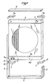
- Fig. 1 is an exploded schematic perspective of a radiator and its support cradle applying the invention.
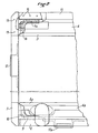
- the freeze 2 is a partial elevation, on a larger scale, partially cut away, illustrating a detail of construction.
- a schematic representation is shown of a cooling radiator for vehicles, in particular for heavy goods vehicles, which comprise tubes 1 and dissipators 2.
- the tubes open into collectors 3, 3a which are covered by water boxes 4, 4a provided with tubes such as those shown in 5 and 5a.
- the radiator itself does not have side cheeks, that is to say that the collectors and water boxes are only connected by the tubes 1. It would not however depart from the scope of the invention if the radiator had side cheeks for connect the small sides of the collectors or water boxes.
- the radiator described above is intended to be mounted in a cradle which has a sole 6, for example constituted by a U-shaped section, and which is joined at its ends to uprights? and 8 also constituted by profiles, for example in a U shape.
- the internal face 11 of the bracket is shaped in a complementary manner to the part of the corresponding wall of the water box 4a.
- the elastic wedges 9 can be solid or, on the contrary, honeycombed, for example having ribs extending in several directions to make a cross-over.
- each wedge in the form of a square is tightened against the wall of the risers 7 and 8.
- other wedges 9a identical to the preceding ones which surround the ends of the water box 4.
- a cover 13 is then placed between the end of the uprights 7, 8.
- the cover 13 is put in place while exerting a pressure on it deforming the long side of the shims 9a and 9 and, then, the cover 13 is fixed to the uprights 7, 8 of the cradle, for example by gussets 14 which are connected to the uprights 7, 8 by welding points 15 and to the cover 13 by bolts or pins 16.
- the radiator is kept under permanent compression stress.
- the elasticity of the shims 9, 9a is chosen taking into account the mass of the radiator proper and a compression force is exerted on the shims such that the natural frequency of the radiator pinched between the different elastic shims is always greater than the frequencies that can be produced by the rolling of the vehicle which includes the radiator.
- the natural frequency of the radiator is greater than 1 Hz, but preferably the compression stress which is exerted is chosen so that this natural frequency is much higher, for example close to 30 Hz.
- the cradle which consists of the sole 6, the uprights 7, 8 and the cover 13, is used to fix the radiator to the vehicle proper by conventional means and, to this end, as illustrated in FIG. 2, it comprises fixing lugs 17, 17a carried by the mon aunts, the sole and possibly the cover.
- the elastic shims consist of rubber or similar material parts, but it would not go beyond the scope of the invention to make them in other ways, for example by metal springs interposed between the lower water box and the sole, on the one hand, and between the upper water box and the cover 13, on the other hand. Similarly, it is possible to combine rubber shims and springs.
Landscapes
- Engineering & Computer Science (AREA)
- Chemical & Material Sciences (AREA)
- Combustion & Propulsion (AREA)
- Transportation (AREA)
- Mechanical Engineering (AREA)
- Cooling, Air Intake And Gas Exhaust, And Fuel Tank Arrangements In Propulsion Units (AREA)
- Vibration Prevention Devices (AREA)
Abstract
Le radiateur est disposé dans un berceau 6, 7, 8, 13 le maintenant sous une précontrainte par des cales élastiques 9, 9a, pour que sa fréquence propre de vibration soit supérieure aux fréquences engendrées par le roulement du véhicule qui le porte; fixation de radiateurs dans des véhicules poids-lourds.The radiator is placed in a cradle 6, 7, 8, 13 keeping it under prestressing by elastic shims 9, 9a, so that its natural frequency of vibration is greater than the frequencies generated by the rolling of the vehicle carrying it; fixing of radiators in heavy vehicles.
Description
Dispositif de fixation pour radiateur dans un véhicule roulant, notamment pour radiateur de véhicule poids-lourd.Fixing device for a radiator in a rolling vehicle, in particular for a truck radiator.
La présente invention concerne le montage de radiateurs, notamment de radiateurs de refroidissement, dans des véhicules poids-lourds destinés à être exploités dans des conditions sévères, par exemple sur des véhicules destinés à rouler sur des pistes.The present invention relates to the mounting of radiators, in particular cooling radiators, in heavy goods vehicles intended to be operated under severe conditions, for example on vehicles intended to roll on tracks.
Il a été constaté que le châssis des véhicules roulant sur des pistes ou autres terrains peu ou non préparés est soumis à des torsions et il arrive que ces efforts de torsion soient transmis aux organes de suspension du ou des radiateurs et provoquent des dommages à ces derniers.It has been observed that the chassis of vehicles traveling on poorly prepared or unprepared tracks or other terrains is subjected to torsions and it sometimes happens that these torsional forces are transmitted to the suspension members of the radiator or radiators and cause damage to the latter. .
Pour remédier à cela, on a proposé des suspensions élastiques pour les radiateurs et il a même déjà été envisagé par la Demanderesse de monter les radiateurs à l'intérieur d'un berceau ou d'une ceinture en reliant le radiateur à cette ceinture par des fixations rigides et localisées, par exemple par des goujons, des plots ou autres organes analogues.To remedy this, elastic suspensions have been proposed for the radiators and it has even been envisaged by the Applicant to mount the radiators inside a cradle or a belt by connecting the radiator to this belt by rigid and localized fasteners, for example by studs, studs or the like.
Malgré ces précautions, il est apparu que des ruptures pouvaient encore se produire.Despite these precautions, it appeared that ruptures could still occur.
L'invention concerne, en conséquence, un nouveau dispositif qui permet de remédier aux inconvénients constatés et de protéger très efficacement le radiateur qui, de plus, peut être réalisé de façon particulièrement bon marché.The invention therefore relates to a new device which makes it possible to remedy the drawbacks noted and to very effectively protect the radiator which, moreover, can be produced in a particularly inexpensive manner.
Conformément à l'invention, le dispositif de fixation pour radiateurs dans un véhicule roulant, notamment pour radiateur de véhicule poids-lourd, comporte un berceau entourant le radiateur et des cales élastiques interposées entre les boites à eau du radiateur et les parties correspondantes du berceau, lesdites cales élastiques étant maintenues sous contrainte pour exercer un effort de compression permanent sur le radiateur.According to the invention, the fixing device for radiators in a rolling vehicle, in particular for a truck radiator, comprises a cradle surrounding the radiator and elastic wedges interposed between the radiator water boxes and the corresponding parts of the cradle , said elastic wedges being maintained under stress to exert a permanent compression force on the radiator.
Diverses autres caractéristiques de l'invention ressortent d'ailleurs de la description détaillée qui suit.Various other characteristics of the invention will also emerge from the detailed description which follows.
Une forme de réalisation de l'objet de l'invention est représentée, à titre d'exemple,non limitatif, au dessin annexé.An embodiment of the object of the invention is shown, by way of example, without limitation, in the accompanying drawing.
La fig. 1 est une perspective schématique éclatée d'un radiateur et de son berceau de support faisant application de l'invention.Fig. 1 is an exploded schematic perspective of a radiator and its support cradle applying the invention.
La fige 2 est une élévation partielle, à plus grande échelle, en partie arrachée, illustrant un détail de réalisation.The freeze 2 is a partial elevation, on a larger scale, partially cut away, illustrating a detail of construction.
Au dessin, est représenté de façon schématique un radiateur de refroidissement pour véhicules, notamment pour poids-lourds, qui comportent des tubes 1 et des dissipateurs 2. Les tubes débouchent dans des collecteurs 3, 3a qui sont recouverts par des boites à eau 4, 4a munies de tubulures telles que celles figurées en 5 et 5a.In the drawing, a schematic representation is shown of a cooling radiator for vehicles, in particular for heavy goods vehicles, which comprise
Dans l'exemple représenté, le radiateur proprement dit ne comporte pas de joues latérales, c'est-à-dire que les collecteurs et boites à eau sont seulement reliés par les tubes 1. On ne sortirait cependant pas du cadre de l'invention si le radiateur comportait des joues latérales pour relier les petits c8tés des collecteurs ou des boites à eau.In the example shown, the radiator itself does not have side cheeks, that is to say that the collectors and water boxes are only connected by the
Le radiateur décrit ci-dessus est destiné à être monté dansun berceau qui comporte une semelle 6, par exemple constituée par un profilé en U, et qui est réunie par ses extrémités à des montants ? et 8 également constitués par des profilés par exemple en U.The radiator described above is intended to be mounted in a cradle which has a sole 6, for example constituted by a U-shaped section, and which is joined at its ends to uprights? and 8 also constituted by profiles, for example in a U shape.
Le radiateur est inséré entre les deux montants ? et 8 et il repose sur la semelle 6 par l'intermédiaire de cales élastiques 9, par exemple en caoutchouc, qui, dans l'exemple illustré, présentent sensiblement la forme d'une équerre dans l'angle externe de laquelle une encoche 10 est formée pour que seules les branches de l'équerre portent, d'une part, contre la semelle 6 et, d'autre part, contre la paroi interne des montants 7, 8.Is the radiator inserted between the two uprights? and 8 and it rests on the sole 6 by means of
La face interne 11 de l'équerrre est conformée de façon complémentaire à la partie de la paroi correspondante de la boite à eau 4a. Les cales élastiques 9 peuvent être pleines ou au contraire alvéolées, par exemple présenter des nervures s'étendant dans plusieurs directions pour réaliser un croisillonnement.The internal face 11 of the bracket is shaped in a complementary manner to the part of the corresponding wall of the
Lors de l'insertion du radiateur entre les montants 7, 8, le petit côté 12 de chaque cale en forme d'équerre est serré contre la paroi des montante 7 et 8. Après insertion complète du radiateur entre les montants, on dispose de façon analogue à ce qui vient d'être décrit d'autres cales 9a identiques aux précédentes qui enveloppent les extrémités de la boite à eau 4. Un couvercle 13 est ensuite mis en place entre l'extrémité des montants 7, 8.During the insertion of the radiator between the
Le couvercle 13 est mis en place tout en exerçant sur lui une pression faisant déformer le grand côté des cales 9a et 9 et, ensuite, le couvercle 13 est fixé aux montants 7, 8 du berceau, par exemple par des goussets 14 qui sont reliés aux montants 7, 8 par des points de soudure 15 et au couvercle 13 par des boulons ou des broches 16. Ainsi, lorsque le couvercle est en place, le radiateur est maintenu soustune contrainte permanente de compression.The
On choisit l'élasticité des cales 9, 9a compte tenu de la masse du radiateur proprement dit et on fait exercer sur les cales une force de compression telle que la fréquence propre du radiateur pincé entre les différentes cales élastiques soit toujours supérieure aux fréquences pouvant être produites par le roulement du véhicule qui comporte le radiateur.The elasticity of the
Dans la plupart des cas, il importe donc que la fréquence propre du radiateur soit supérieure à 1 hz, mais de préférence la contrainte de compression qui est exercée est choisie pour que cette fréquence propre soit très supérieure, par exemple voisine de 30 hz.In most cases, it is therefore important that the natural frequency of the radiator is greater than 1 Hz, but preferably the compression stress which is exerted is chosen so that this natural frequency is much higher, for example close to 30 Hz.
Le berceau, qui est constitué par la semelle 6, les montants 7, 8 et le couvercle 13, est utilisé pour fixer le radiateur au véhicule proprement dit par des moyens habituels et, à cette fin, comme l'illustre la fig. 2, il comporte des pattes de fixation 17, 17a portées par les montants, la semelle et éventuellement le couvercle.The cradle, which consists of the sole 6, the
Dans ce qui précède, il a été expliqué que les cales élastiques étaient constituées par des pièces en caoutchouc ou matière analogue mais on ne sortirait pas du cadre de l'invention en les réalisant d'autres manières, par exemple par des ressorts métalliques interposés entre la boite à eau inférieure et la semelle, d'une part, et entre la boîte à eau supérieure et le couvercle 13, d'autre part. De même, il est possible de combiner des cales en caoutchouc et des ressorts.In the foregoing, it has been explained that the elastic shims consist of rubber or similar material parts, but it would not go beyond the scope of the invention to make them in other ways, for example by metal springs interposed between the lower water box and the sole, on the one hand, and between the upper water box and the
L'invention n'est pas limitée à l'exemple de réalisation, représenté et décrit en détail, car diverses modifications peuvent y être apportées sans sortir de son cadre.The invention is not limited to the embodiment, shown and described in detail, because various modifications can be made without departing from its scope.
Claims (8)
Applications Claiming Priority (2)
| Application Number | Priority Date | Filing Date | Title |
|---|---|---|---|
| FR7911294A FR2455524A1 (en) | 1979-05-04 | 1979-05-04 | FIXING DEVICE FOR RADIATOR IN A ROLLING VEHICLE, IN PARTICULAR FOR A HEAVY-DUTY VEHICLE RADIATOR |
| FR7911294 | 1979-05-04 |
Publications (2)
| Publication Number | Publication Date |
|---|---|
| EP0020190A1 true EP0020190A1 (en) | 1980-12-10 |
| EP0020190B1 EP0020190B1 (en) | 1983-04-06 |
Family
ID=9225050
Family Applications (1)
| Application Number | Title | Priority Date | Filing Date |
|---|---|---|---|
| EP80400493A Expired EP0020190B1 (en) | 1979-05-04 | 1980-04-14 | Device for securing a radiator in a mobile vehicle, in particular a radiator of a load-carrying vehicle |
Country Status (8)
| Country | Link |
|---|---|
| US (1) | US4315540A (en) |
| EP (1) | EP0020190B1 (en) |
| BR (1) | BR8002670A (en) |
| DD (1) | DD150446A5 (en) |
| DE (1) | DE3062587D1 (en) |
| ES (1) | ES8100636A1 (en) |
| FR (1) | FR2455524A1 (en) |
| PL (1) | PL223987A1 (en) |
Cited By (2)
| Publication number | Priority date | Publication date | Assignee | Title |
|---|---|---|---|---|
| FR2538030A1 (en) * | 1982-12-16 | 1984-06-22 | Chausson Usines Sa | LONG TUBE HEAT EXCHANGER FOR HEAVY DUTY VEHICLES |
| DE19916475A1 (en) * | 1999-04-13 | 2000-10-19 | Behr Gmbh & Co | Heat transfer unit for a motor vehicle |
Families Citing this family (12)
| Publication number | Priority date | Publication date | Assignee | Title |
|---|---|---|---|---|
| JPS5784223A (en) * | 1980-11-13 | 1982-05-26 | Nissan Motor Co Ltd | Vibration absorber of vehicle |
| US5088572A (en) * | 1991-03-28 | 1992-02-18 | Navistar International Transportation Corp. | Forward control bus chassis with low engine mounting assembly |
| DE9213450U1 (en) * | 1992-10-06 | 1993-01-07 | Cummins Engine Co. Ltd., New Malden, Surrey | Drive unit |
| GB9805379D0 (en) * | 1998-03-14 | 1998-05-06 | Grayson Automotive Services Li | Heat exchanger assemblies for vehicles |
| GB2336662B (en) * | 1998-04-21 | 2002-04-10 | Agco Gmbh & Co | Vehicle cooling radiator arrangement |
| DE19831256A1 (en) * | 1998-07-11 | 2000-01-13 | Behr Gmbh & Co | Holder for heat exchanger esp. for motor vehicle radiators has frame of expanded polypropylene forming air guide frame around heat exchanger |
| JP4400803B2 (en) * | 1999-09-03 | 2010-01-20 | 本田技研工業株式会社 | Vehicle cooling system |
| DE10061561A1 (en) * | 2000-12-07 | 2002-06-13 | Behr Gmbh & Co | Module carrier for various heat exchangers of a motor vehicle engine |
| US7195059B2 (en) * | 2003-05-06 | 2007-03-27 | H2Gen Innovations, Inc. | Heat exchanger and method of performing chemical processes |
| JP2005112268A (en) * | 2003-10-10 | 2005-04-28 | Nissan Motor Co Ltd | Mounting structure for heat exchanger |
| DE102005039090A1 (en) * | 2005-08-06 | 2007-02-08 | Behr Gmbh & Co. Kg | Assembly support system |
| JP6804269B2 (en) * | 2016-11-18 | 2020-12-23 | 三菱重工サーマルシステムズ株式会社 | Heat exchanger |
Citations (5)
| Publication number | Priority date | Publication date | Assignee | Title |
|---|---|---|---|---|
| FR599781A (en) * | 1925-06-18 | 1926-01-20 | Int Motor Co | Improvements to automotive radiator brackets |
| FR1413650A (en) * | 1964-11-07 | 1965-10-08 | Daimler Benz Ag | Elastic fixing of a radiator on motor cars |
| FR1413728A (en) * | 1964-11-12 | 1965-10-08 | Daimler Benz Ag | Elastic fixing of the radiator on motor cars |
| FR1600374A (en) * | 1968-12-31 | 1970-07-20 | ||
| US4137982A (en) * | 1977-08-08 | 1979-02-06 | Caterpillar Tractor Co. | Reinforced radiator mounting for heavy vehicles |
Family Cites Families (9)
| Publication number | Priority date | Publication date | Assignee | Title |
|---|---|---|---|---|
| US1447695A (en) * | 1921-09-27 | 1923-03-06 | Claude V Storms | Radiator support |
| US1593244A (en) * | 1921-10-19 | 1926-07-20 | Cutler Auto Radiator Company | Automobile radiator |
| US1840417A (en) * | 1930-03-19 | 1932-01-12 | Mcquay Radiator Corp | Frame and mounting for heat exchange units |
| US1834709A (en) * | 1930-08-22 | 1931-12-01 | Fedders Mfg Co | Radiator mounting |
| US1963429A (en) * | 1932-07-08 | 1934-06-19 | Fred M Young | Radiator |
| US2506051A (en) * | 1947-09-12 | 1950-05-02 | Young Radiator Co | Radiator core mounting |
| US2755874A (en) * | 1951-12-04 | 1956-07-24 | Gen Motors Corp | Motor vehicle radiators resiliently and slidably mounted |
| DE2233737C2 (en) * | 1971-07-12 | 1983-02-03 | Société Anonyme Française du Ferodo, 75017 Paris | Heat exchangers, in particular radiators for a motor vehicle |
| US3858291A (en) * | 1972-01-31 | 1975-01-07 | Garrett Corp | Method of mounting a heat exchanger core |
-
1979
- 1979-05-04 FR FR7911294A patent/FR2455524A1/en active Granted
-
1980
- 1980-04-14 EP EP80400493A patent/EP0020190B1/en not_active Expired
- 1980-04-14 DE DE8080400493T patent/DE3062587D1/en not_active Expired
- 1980-04-25 US US06/145,269 patent/US4315540A/en not_active Expired - Lifetime
- 1980-04-28 ES ES490972A patent/ES8100636A1/en not_active Expired
- 1980-04-30 BR BR8002670A patent/BR8002670A/en unknown
- 1980-05-03 PL PL22398780A patent/PL223987A1/xx unknown
- 1980-05-05 DD DD80220891A patent/DD150446A5/en unknown
Patent Citations (5)
| Publication number | Priority date | Publication date | Assignee | Title |
|---|---|---|---|---|
| FR599781A (en) * | 1925-06-18 | 1926-01-20 | Int Motor Co | Improvements to automotive radiator brackets |
| FR1413650A (en) * | 1964-11-07 | 1965-10-08 | Daimler Benz Ag | Elastic fixing of a radiator on motor cars |
| FR1413728A (en) * | 1964-11-12 | 1965-10-08 | Daimler Benz Ag | Elastic fixing of the radiator on motor cars |
| FR1600374A (en) * | 1968-12-31 | 1970-07-20 | ||
| US4137982A (en) * | 1977-08-08 | 1979-02-06 | Caterpillar Tractor Co. | Reinforced radiator mounting for heavy vehicles |
Cited By (4)
| Publication number | Priority date | Publication date | Assignee | Title |
|---|---|---|---|---|
| FR2538030A1 (en) * | 1982-12-16 | 1984-06-22 | Chausson Usines Sa | LONG TUBE HEAT EXCHANGER FOR HEAVY DUTY VEHICLES |
| EP0112251A1 (en) * | 1982-12-16 | 1984-06-27 | Societe Anonyme Des Usines Chausson | Long-tube heat exchanger for heavy load vehicles |
| DE19916475A1 (en) * | 1999-04-13 | 2000-10-19 | Behr Gmbh & Co | Heat transfer unit for a motor vehicle |
| US6601640B1 (en) | 1999-04-13 | 2003-08-05 | Behr Gmbh & Co. | Heat transmission unit for a motor vehicle |
Also Published As
| Publication number | Publication date |
|---|---|
| ES490972A0 (en) | 1980-12-01 |
| PL223987A1 (en) | 1981-02-27 |
| DD150446A5 (en) | 1981-09-02 |
| BR8002670A (en) | 1980-12-09 |
| EP0020190B1 (en) | 1983-04-06 |
| ES8100636A1 (en) | 1980-12-01 |
| US4315540A (en) | 1982-02-16 |
| FR2455524A1 (en) | 1980-11-28 |
| FR2455524B1 (en) | 1983-06-03 |
| DE3062587D1 (en) | 1983-05-11 |
Similar Documents
| Publication | Publication Date | Title |
|---|---|---|
| EP0020190A1 (en) | Device for securing a radiator in a mobile vehicle, in particular a radiator of a load-carrying vehicle | |
| FR2508398A1 (en) | BUMPER FOR MOTOR VEHICLES | |
| FR3065416A1 (en) | FRONT VEHICLE STRUCTURE COMPRISING A BUMPER WITH PROTUBERANCE AGENT TO DEFORM AT A DECAL SHOCK | |
| FR2474981A1 (en) | BUMPER CONSTRUCTION FOR A MOTOR VEHICLE | |
| EP0025399B1 (en) | Independent vehicle wheel chock | |
| EP1580096A1 (en) | Vehicle frame comprising an antivibration device | |
| EP3256348B1 (en) | Rear bumper central support | |
| WO2017187037A1 (en) | Vehicle door with reinforcer and vehicle comprising such a door | |
| FR2905925A1 (en) | Frontal impact energy absorbing device for motor vehicle, has foam with energy absorbing properties, housed in casing, fixation plate fixing device on part of vehicle, and deformation element with reinforcements, formed by casing edges | |
| EP1059466B1 (en) | Engine mount with non-elastic wire movement limiter | |
| EP1106467A1 (en) | Device for controlled deformation by forces or for absorption of energy by deformation, especially obstacle deflector for a railway vehicle | |
| FR2767508A1 (en) | Loading buffer for cargo motor vehicle | |
| FR2757591A1 (en) | Energy damping assembly for machine, doing civil engineering related work, with chassis and balance beam for traction elements | |
| FR2701753A1 (en) | Device for joining members of an exhaust line, especially for a motor vehicle, with an articulation | |
| EP3749533A1 (en) | Vehicle shock absorber with a holding strap and associated mounting method | |
| FR2742063A1 (en) | In-line roller skate with boot, frame and shock absorbers | |
| FR2860760A1 (en) | Shock absorbing pad for motor vehicle e.g. truck, has roller with peripheral annular part that is elastically deformable such that, under effect of force applied on part, part is supported on casing situated in front of elastic core | |
| FR2859952A1 (en) | Elastic support for exhaust line of motor vehicle, has sleeve connected to plate by flattened tubular section, where axes of section and sleeve extend along transversal axis and are orthogonal to vertical axis and longitudinal axis | |
| FR2764242A1 (en) | Locking of vehicle anti-roll bar bearings | |
| EP3577348B1 (en) | Device for retaining a part on a support | |
| FR3057237B1 (en) | ALLEGED LOAD FOR MOTOR POWERS THAT LIMITS VERTICAL EFFORTS | |
| FR2926275A1 (en) | Roller assembly for guiding carrying cable of mechanical lift, has frame with flanges composed of plates articulated between them around articulation axle, and elastic units intercalated between plates to dampen pivoting of plates | |
| WO2021064307A1 (en) | Side impact absorber for a motor vehicle | |
| FR2620659A1 (en) | Spacing device for suspension with curved leaves | |
| BE561175A (en) |
Legal Events
| Date | Code | Title | Description |
|---|---|---|---|
| PUAI | Public reference made under article 153(3) epc to a published international application that has entered the european phase |
Free format text: ORIGINAL CODE: 0009012 |
|
| 17P | Request for examination filed | ||
| AK | Designated contracting states |
Designated state(s): BE DE GB IT NL SE |
|
| ITCL | It: translation for ep claims filed |
Representative=s name: KOHLER FONTANA |
|
| DET | De: translation of patent claims | ||
| ITF | It: translation for a ep patent filed | ||
| GRAA | (expected) grant |
Free format text: ORIGINAL CODE: 0009210 |
|
| AK | Designated contracting states |
Designated state(s): BE DE GB IT NL SE |
|
| REF | Corresponds to: |
Ref document number: 3062587 Country of ref document: DE Date of ref document: 19830511 |
|
| PLBI | Opposition filed |
Free format text: ORIGINAL CODE: 0009260 |
|
| PLBI | Opposition filed |
Free format text: ORIGINAL CODE: 0009260 |
|
| 26 | Opposition filed |
Opponent name: KUEHLERFABRIK LAENGERER & REICH GMBH & CO. KG Effective date: 19831223 |
|
| 26 | Opposition filed |
Opponent name: SUEDDEUTSCHE KUEHLERFABRIK JULIUS FR. BEHR GMBH & Effective date: 19840103 Opponent name: DAIMLER-BENZ AKTIENGESELLSCHAFT Effective date: 19831230 |
|
| PGFP | Annual fee paid to national office [announced via postgrant information from national office to epo] |
Ref country code: DE Payment date: 19840522 Year of fee payment: 5 |
|
| PGFP | Annual fee paid to national office [announced via postgrant information from national office to epo] |
Ref country code: SE Payment date: 19840630 Year of fee payment: 5 Ref country code: BE Payment date: 19840630 Year of fee payment: 5 |
|
| PGFP | Annual fee paid to national office [announced via postgrant information from national office to epo] |
Ref country code: NL Payment date: 19860430 Year of fee payment: 7 |
|
| RDAG | Patent revoked |
Free format text: ORIGINAL CODE: 0009271 |
|
| STAA | Information on the status of an ep patent application or granted ep patent |
Free format text: STATUS: PATENT REVOKED |
|
| 27W | Patent revoked |
Effective date: 19870205 |
|
| NLR2 | Nl: decision of opposition | ||
| GBPR | Gb: patent revoked under art. 102 of the ep convention designating the uk as contracting state | ||
| BERE | Be: lapsed |
Owner name: S.A. DES USINES CHAUSSON Effective date: 19870430 |
|
| EUG | Se: european patent has lapsed |
Ref document number: 80400493.5 Effective date: 19880906 |