EP0020093A1 - Filter für Flüssigkeiten - Google Patents
Filter für Flüssigkeiten Download PDFInfo
- Publication number
- EP0020093A1 EP0020093A1 EP80301695A EP80301695A EP0020093A1 EP 0020093 A1 EP0020093 A1 EP 0020093A1 EP 80301695 A EP80301695 A EP 80301695A EP 80301695 A EP80301695 A EP 80301695A EP 0020093 A1 EP0020093 A1 EP 0020093A1
- Authority
- EP
- European Patent Office
- Prior art keywords
- filter
- support
- ribs
- fingers
- skeleton
- Prior art date
- Legal status (The legal status is an assumption and is not a legal conclusion. Google has not performed a legal analysis and makes no representation as to the accuracy of the status listed.)
- Withdrawn
Links
Images

Classifications
-
- A—HUMAN NECESSITIES
- A47—FURNITURE; DOMESTIC ARTICLES OR APPLIANCES; COFFEE MILLS; SPICE MILLS; SUCTION CLEANERS IN GENERAL
- A47J—KITCHEN EQUIPMENT; COFFEE MILLS; SPICE MILLS; APPARATUS FOR MAKING BEVERAGES
- A47J31/00—Apparatus for making beverages
- A47J31/44—Parts or details or accessories of beverage-making apparatus
- A47J31/4403—Constructional details
- A47J31/446—Filter holding means; Attachment of filters to beverage-making apparatus
Definitions
- This invention relates to filters and more particularly to liquid filters.
- the invention is particularly applicable to a permanent, reuseable and foldable filter for automatic coffee brewing apparatus and will be described with particular reference thereto.
- the concepts of the invention have broader applications and may be utilized in other environments and apparatus for filtering other liquids and liquid-like substances.
- drip type coffee makers have been used in commercial establishments for many years. In recent years, however, drip type coffee makers for home use have been introduced into the marketplace and have received wide customer recognition. Basically, drip type coffee makers utilize prepackaged or a measured amount of dry coffee granules placed in a filter basket which communicates with a source of hot water. A predetermined amount of hot water is introduced into the filter basket to intermix with the coffee granules, and be converted into coffee. This coffee then flows from the bottom area of the filter basket into a conventional serving container or carafe. Typical of such home type drip coffee makers are those manufactured by North American Systems, Inc..of Cleveland, Ohio under the trademark MR. COFFEE.
- a filter is inserted into the filter basket which, in turn, receives the coffee granules.
- This filter acts to prevent the granules or grounds themselves from undesirably passing through the filter basket into the serving container or carafe.
- the vast majority.of these filters have been constructed from a paper-like material. As such, they are only useable once and 'are then discarded along with the coffee grounds when brewing has been completed.
- Such disposable paper filters are packaged in quantity and typically have a generally cup-shaped configuration with a flat bottom wall area and a pleated side wall. Because of this shape, the quantity packaging requires added shelf storage space. Moreover, the pleated side wall can allow passage of hot water between the filter basket side wall and filter without contacting the coffee granules to thereby dilute the coffee being brewed.
- the rigid skeleton which preforms the filter does not allow substantial variation in the type of filter basket with which it is used to that a wide variety of types and styles is necessarily required to suit the coffee brewing apparatus of different manufacturers.
- the rigid cup-shaped skeleton or frame requires additional materials which increases manufacturing costs and resultant resale costs to the consumer.
- these filters since these filters are supplied in a preformed cup-shaped configuration, they necessarily require packaging in somewhat larger boxes or the likeo As. with the disposable paper filters, this reduces the number of such filters which may be placed on typical store shelves and thereby necessitates more frequent restocking.
- An object of the present invention is to provide a new filter design and construction which is easy to manufacture, inexpensive to manufacture, reuseable for an extended period of time, selectively foldable between a generally flat storage condition and a use condition with associated support structure and readily adapted for use in a number of different environments for filtering different liquids.
- a liquid filter comprises a thin flexible filter material having a porosity adapted to filter a liquid passing therethrough to some desired extent; and a support skeleton for supporting said filter material and for providing it with a desired form at least when placed in co-operative communication with some associated structure, characterised in that the support skeleton includes a support rim and a plurality of ribs or fingers extending outwardly therefrom towards the outer peripheral edge of the filter material.
- a permanent reusable liquid filter construction comprising a thin: filter material having a porosity adapted to filter a beverage passing therethrough to a desired-extent and a support skeleton for giving support to said filter material,characterised in that the support skeleton affixed to one face of the filter material includes a central portion generally centrally disposed on said filter material and configured to define a filter bottom area when said filter is received in a generally cup-shaped filter support and further includes a plurality of skeleton ribs or fingers at spaced intervals around said central portion extending outwardly thereof towards the outer peripheral edge of the filter material and in that the skeleton is so constructed that the filter is self-folding between a first generally flat storage condition and a second generally cup-shaped filtering condition as it is inserted into the generally cup-shaped filter support, said ribs or fingers providing support for said filter material outwardly of said skeleton central portion and adapted to provide a generally cup-shaped configuration therefor when said filter
- the skeleton support rim and ribs are constructed from a plastics material and are mechanically bonded to the one face of the filter material.
- the filter material comprises a cloth-like construction of material having low moisture absorption characteristics.
- the support ribs or fingers comprise a plurality of rib or finger sets. Each such set includes a plurality of adjacent ribs interconnected with one another by at least one first connecting web.
- the first connecting webs are-disposed at least adjacent terminal ends of the ribs in the associated set which are spaced towards the support rim.
- each finger set' is also connected to the support rim by a second connecting web.
- this connecting web generally comprises a radial extension of one of the ribs or fingers in the associated rib or finger set.
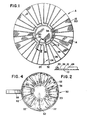
- Figure 1 shows a beverage or coffee filter construction comprised of a thin, flexible filter material A having a support web or skeleton B fixedly secured thereto.
- filter material A has a flat inner face 10, a flat outer face 12 and an outer peripheral edge 14.
- edge 14 is generally circular, although other configurations could also be utilized to accommodate a particular filter application.
- Filter material A could be comprised of any number of different materials including plastics materials such as polypropylene and polyvinylchloride or could even be constructed from a flexible metallic mesh.
- a monofilament cloth comprised of a square-mesh screen fabric manufactured from synthetic monofilament yarns is preferred. Such materials are manufactured and marketed by Industrial Fabrics Corporation of Minneapolis, Minnesota.
- filter material A do not, in and of themselves, form a part of the invention and are not, therefore, described in greater detail.
- the porosity, permeability or mesh opening . sizes of filter material. A are selected in a range which will allow the desired flow of coffee therethrough while preventing passage of the coffee grounds.
- the particular porosity or mesh size will, to some extent, depeiid upon the specific material utilized for filter material A and will also depend on the intended filter use. Accordingly, it is not deemed necessary to discuss this feature in greater detail herein.
- Use of a filter material which is low in moisture absorption is desired when the filter is to be employed with coffeemakers in order to prevent absorption of oils from the coffee granules or grounds during extended periods of use. Any such absorption might otherwise render the coffee bitter or rancid.
- Web or skeleton B is comprised of a central portion or support rim 20 and a plurality of support ribs or fingers 24, 26, 28 extending radially outward thereof.
- the central portion or support rim 20 is generally centrally disposed on outer face 12 of filter material A.
- rim 20 is generally circular to define a circular bottom wall in order to fit in a conventional coffeemaker filter basket as will become more apparent hereinafter. It will be understood, however, that other support rim configurations can also be used to suit the particular application or use.
- the ribs or'fingers are arranged in a plurality of rib or finger sets generally designated 22 wherein each set is comprised of a plurality of interconnected ribs. In the preferred arrangement, sets 22 are identical with each other and three separate ribs designated 24, 26 and 28 are employed in each set.
- the inner end 30 of each rib is spaced adjacent to support rim 20 and its outer end 32 terminates at filter material outer peripheral edge 14.
- a first connecting web 34 extends between inner ends 30 of ribs or. fingers 24, 26 and 28 of each set 22 for connecting the ribs together.
- a second connecting web 36 extends generally radially from each set 22 to support rim 20 for connecting the individual sets to the support rim.
- second connecting webs 36 generally comprise a radial extension of an end one of the ribs in each rib set 22 and, more particularly, comprise extensions of ribs 24.
- support rim 20 and rib 24 have a slightly larger cross-sectional area than second connecting web 36. This is to facilitate ease of bending between rib sets 22 and the support rim when the filter construction is inserted into a filter basket as will be described.
- support rim 20 and ribs 24, 26 and 28 are generally square in cross-section and measure approximately 1.6 mm on a side.
- Second connecting web 36 is also square but somewhat smaller in dimension, measuring approximately 0.5 mm to 0.75 mm on a side. However, these dimensions may be varied as necessary or desired within the present invention.
- each rib set 22 is comprised of three ribs with a total of ten such sets spaced radially around rim 20. With such a construction, all the ribs are spaced apart from the next adjacent ribs by angles of approximately 12°. This too may be varied as desired along with the other design parameters without in any way departing from the invention.
- central portion or support rim 20 and rib or finger sets 22 of web or skeleton B are constructed from polypropylene, although other plastics materials and other materials could also be advantageously employed'.
- the skeleton may be integrally moulded so as to include rim 20, rib sets 22, first connecting webs.34 and second connecting webs 36 as a single piece construction or may be fabricated from several pieces.
- the precise method of manufacture may, to some extent, be dictated by the details of the intended filter application. For purposes of use in coffeemakers, it is particularly desired that the skeleton be non-absorbent and also be fairly rigid to give form to the overall filter construction.
- the material should be heat bondable to filter material A since this is the preferred form of affixing the web or skeleton B to the filter material. While some types of glues may be acceptable, their use is purposely avoided in conjunction with beverages to eliminate any possible distortion of beverage taste. In addition to heat bonding, other types of mechanical bonding arrangements could be satisfactorily employed.
- FIG 3 shows the filter construction of Figure 1 as it is being inserted into a filter basket 50 for a drip type coffeemaker.
- the filter basket has a cup-shaped configuration with a generally circular open top end 52 and a side wall'54 which tapers inwardly from the top end toward a generally circular bottom wall or end 56.
- a handle 58 is conveniently affixed to side wall 54 for ease of installing and removing the filter basket from operative communication with coffee brewing apparatus.
- Bottom end or wall 56 includes one or more openings generally centrally thereof for purposes of allowing coffee to flow therethrough into a container or carafe spaced immediately thereunder.
- Filter basket 50 may, of course, take a variety of shapes and forms and be constructed from a variety of materials.
- FIG. 3 the general showing of Figure 3 should allow those skilled in the art to readily appreciate the use of the filter construction in accordance with the invention.
- filter material inner face 10 faces upwardly from the filter basket with support rim 20 and rib sets 22 of web or skeleton B which are bonded to outer surface 12 facing downwardly towards the filter basket.
- the filter itself is normally in a flat condition as shown in Figures 1 and 3 in order to facilitate ease of packing and storage and to substantially reduce the necessary shelf space required for such storage.
- the filter is simply pushed into the filter basket in the ⁇ direction of arrow a until it is positioned as generally shown in Figure 4.
- Support rim 20 is circular and has a diameter generally the same or slightly smaller than the diameter of filter basket bottom end or wall 56. As shown, rib or finger sets 22 are bent upwardly from support rim 20 at the area of first connecting webs 34 in order to generally assume the same :cup-like configuration of the filter basket..
- the filter Since the filter is being folded from a generally flat condition to a generally cup-shaped condition, there will be some excess filter material. Due to the relative rigidity of the individual ribs 24, 26 and 28 as compared with filter material A, this excess will appear as folds or flutes 62 between the end ribs 24, 28 of adjacent rib sets 22. These folds extend generally radially inwardly from filter material outer peripheral edge 14 to the area of support rim 20 and are automatically formed as the filter is being inserted. Thus, the filter construction may be fairly catagorized as self-fluting. Moreover, since the natural or normal condition for the filter is generally flat, the natural resiliency of second connecting webs 36 will urge rib sets 22 towards engagement with filter basket side wall 54 at least at and adjacent open top end 52. This, in turn, aids in moving folds 62 to a generally flat condition so that the overall filter construction will conform to the cup-shaped filter basket when inserted thereinto.
- the generally circular configuration of the filter when it is in the flat condition also advantageously maximizes the surface area of filter material available for filtering purposes when the filter is placed in filter basket 50 in the manner described above. This then generally duplicates the filter surface area present in the known types of fluted paper filters. A maximum surface area is desirable since it is this surface area which governs the overall filter efficiency.
- FIG. 5 shows a slightly modified version of the filter hereinabove described.
- like components are identified by like numerals with the addition of a primed ( * ) suffix and any new components are identified by new numerals.
- filter material A' again has a generally circular configuration with an outer peripheral edge 14'.
- rib or finger sets have ribs 24', 26' and 28' which extend radially of centre portion or support rim 20' and terminate at or. adjacent peripheral edge 14'.
- a first connecting web 34' connects ribs 24', 26' and 28' of each rib set 22' together adjacent the innermost ends 30' thereof.
- finger sets 22' and support rim 20' Use of this alternative embodiment is the same as previously described hereinabove with reference to Figures 3 and 4. The only difference in this alternative embodiment is the fact that any resilient outward force otherwise obtained by means of the second connecting web is not provided. Even without the inclusion of the second connecting webs; however, this embodiment has provided wholly adequate and acceptable operational results.
- the filter may be conveniently removed from the filter basket for disposal of the coffee grounds. Thereafter, the filter may be washed or otherwise cleaned for subsequent reuse at the next occasion of coffee brewing.
- the construction and materials employed for the filter construction facilitate such reuse for extended periods of time without physical deterioration and/or without adversely affecting the quality or taste of the coffee.
- While the embodiments of the filter which have been described above utilize ribs or fingers in each finger or rib set and further utilize ten such sets equidistantly spaced around the support rim, these numbers and spacings may be varied as deemed necessary or appropriate to suit particular filter applications. For example, and for smaller sized filters, it may be desirable to only include two ribs per rib set while for larger sized filters, it may be desirable to include a greater number of ribs per set. For use in typical coffeemakers, it is desired that a sufficient number of ribs per rib set be included so that the folds.or flutes generated in the filter material when it is moved from a generally flat to a generally cup-shaped condition will at least substantially lie against the filter basket side wall.
- the flutes will have a tendency to generate a somewhat wave-like configuration around the filter basket side wall. Such a configuration is undesirable in that it may allow hot water injected into the filter basket to pass between the filter and filter basket side wall without first contacting the coffee granules.
- the number and orientation of the rib or finger sets may be appropriately varied.
- the specific configuration of the skeleton central portion or support ring may be varied as necessary to accommodate these other filtering applications. It is further possible to, for example, connect skeleton ribs or fingers directly to the skeleton central portion or support rim.
Landscapes
- Engineering & Computer Science (AREA)
- Food Science & Technology (AREA)
- Apparatus For Making Beverages (AREA)
- Filtration Of Liquid (AREA)
Applications Claiming Priority (2)
| Application Number | Priority Date | Filing Date | Title |
|---|---|---|---|
| US06/041,711 US4271024A (en) | 1979-05-23 | 1979-05-23 | Liquid filter |
| US41711 | 1979-05-23 |
Publications (1)
| Publication Number | Publication Date |
|---|---|
| EP0020093A1 true EP0020093A1 (de) | 1980-12-10 |
Family
ID=21917935
Family Applications (1)
| Application Number | Title | Priority Date | Filing Date |
|---|---|---|---|
| EP80301695A Withdrawn EP0020093A1 (de) | 1979-05-23 | 1980-05-22 | Filter für Flüssigkeiten |
Country Status (4)
| Country | Link |
|---|---|
| US (1) | US4271024A (de) |
| EP (1) | EP0020093A1 (de) |
| JP (1) | JPS55159815A (de) |
| FI (1) | FI801654A (de) |
Cited By (4)
| Publication number | Priority date | Publication date | Assignee | Title |
|---|---|---|---|---|
| EP0309882A2 (de) * | 1987-09-29 | 1989-04-05 | Roche Diagnostics GmbH | Verfahren zur spezifischen Bestimmung des Serumfructosamingehalts sowie hierfür geeignetes Reagenzgemisch |
| EP0717948A1 (de) * | 1994-12-20 | 1996-06-26 | Maxs Ag | Espresso-Dauerfiltereinsatz |
| WO1997040727A1 (de) * | 1996-04-26 | 1997-11-06 | Bauer Juergen | Filtervorrichtung |
| WO2000015090A1 (de) * | 1998-09-11 | 2000-03-23 | Braun Gmbh | Permanentfilter, der zum mehrmaligen filtern von aufgussgetränken, wie kaffee oder tee, dient |
Families Citing this family (15)
| Publication number | Priority date | Publication date | Assignee | Title |
|---|---|---|---|---|
| US4619766A (en) * | 1984-04-23 | 1986-10-28 | Smiley Thomas B | Beverage brewings filters, apparatus and method |
| US4728425A (en) * | 1986-09-26 | 1988-03-01 | Sandvig Larry G | Coffee filter and annular retainer |
| US5252204A (en) * | 1992-08-20 | 1993-10-12 | Manufacturers Components, Inc. | Unimold filter |
| US5292437A (en) * | 1992-09-21 | 1994-03-08 | Bunn-O-Matic Corporation | Multilayer frustoconical filter structure |
| USD383036S (en) * | 1995-11-16 | 1997-09-02 | Kimberly-Clark Corporation | Filter cake holder |
| USD386946S (en) * | 1996-11-19 | 1997-12-02 | Novalle Miriam Y | Disposable tea cup and saucer |
| US6900389B2 (en) * | 2003-01-10 | 2005-05-31 | Fci Americas Technology, Inc. | Cover for ball-grid array connector |
| US9527661B2 (en) * | 2009-09-29 | 2016-12-27 | Lbp Manufacturing Llc | Disposable single use beverage package |
| US9108794B2 (en) | 2009-09-29 | 2015-08-18 | Lbp Manufacturing, Inc. | Disposable single use beverage package |
| GB2475943C (en) * | 2010-09-27 | 2012-07-11 | Howard Marc Gold | Cooking container and cooking method |
| TWM414181U (en) * | 2011-02-10 | 2011-10-21 | ying-yan Zhang | Juice filtration device for preparation of soaking-type drinks |
| US9452879B2 (en) | 2011-07-26 | 2016-09-27 | Lbp Manufacturing Llc | Sealed beverage basket and method of making |
| USD838843S1 (en) * | 2017-04-11 | 2019-01-22 | Edward L. Baton | Liner for receiving human waste products |
| TWI721240B (zh) * | 2018-01-08 | 2021-03-11 | 林紫綺 | 掛耳式杯套結構 |
| CA201328S (en) * | 2021-02-09 | 2022-09-02 | Pentik Oy | Cup |
Citations (2)
| Publication number | Priority date | Publication date | Assignee | Title |
|---|---|---|---|---|
| US2456912A (en) * | 1945-03-22 | 1948-12-21 | Edwin N Burrows | Collapsible and adjustable filter and strainer |
| DE2534065A1 (de) * | 1974-08-07 | 1976-02-19 | Roberto Bartolome Diaz | Kaffeefilter fuer kaffeemaschinen |
Family Cites Families (15)
| Publication number | Priority date | Publication date | Assignee | Title |
|---|---|---|---|---|
| US752019A (en) * | 1904-02-16 | Device for straining liquids | ||
| US723091A (en) * | 1902-09-03 | 1903-03-17 | Powhatan A Webb | Filter for cofee or tea pots. |
| US754053A (en) * | 1903-03-02 | 1904-03-08 | Samuel G Derham | Filtering material. |
| US1192332A (en) * | 1914-05-25 | 1916-07-25 | Max Loewenstein | Tea-strainer. |
| US1209051A (en) * | 1915-09-27 | 1916-12-19 | Francesca C Shotwell | Collapsible funnel. |
| US1246680A (en) * | 1917-03-03 | 1917-11-13 | Joseph A Thomas | Strainer. |
| US1276992A (en) * | 1917-11-17 | 1918-08-27 | Simeon Tadejevich | Strainer. |
| US1480413A (en) * | 1922-10-05 | 1924-01-08 | Pedersen Johannes Th | Coffee urn |
| US1725305A (en) * | 1927-02-03 | 1929-08-20 | Williams Co | Steel-wool machine |
| US1831923A (en) * | 1930-05-19 | 1931-11-17 | Albert W Meyer | Percolator |
| US1889543A (en) * | 1930-12-05 | 1932-11-29 | Coors Porcelain Co | Coffee maker |
| GB614285A (en) * | 1946-07-11 | 1948-12-13 | Winifred May Waller | Improvements in and relating to strainers for tea and coffee pot spouts and the like |
| US3543940A (en) * | 1968-08-14 | 1970-12-01 | Industrial Filter Pump Mfg Co | Filter construction |
| US3651947A (en) * | 1970-03-11 | 1972-03-28 | Melikian Inc Rudd | Filter |
| US3695168A (en) * | 1970-06-02 | 1972-10-03 | George H Van Brunt | Drip coffee maker |
-
1979
- 1979-05-23 US US06/041,711 patent/US4271024A/en not_active Expired - Lifetime
-
1980
- 1980-05-19 JP JP6632180A patent/JPS55159815A/ja active Pending
- 1980-05-21 FI FI801654A patent/FI801654A/fi not_active Application Discontinuation
- 1980-05-22 EP EP80301695A patent/EP0020093A1/de not_active Withdrawn
Patent Citations (2)
| Publication number | Priority date | Publication date | Assignee | Title |
|---|---|---|---|---|
| US2456912A (en) * | 1945-03-22 | 1948-12-21 | Edwin N Burrows | Collapsible and adjustable filter and strainer |
| DE2534065A1 (de) * | 1974-08-07 | 1976-02-19 | Roberto Bartolome Diaz | Kaffeefilter fuer kaffeemaschinen |
Cited By (7)
| Publication number | Priority date | Publication date | Assignee | Title |
|---|---|---|---|---|
| EP0309882A2 (de) * | 1987-09-29 | 1989-04-05 | Roche Diagnostics GmbH | Verfahren zur spezifischen Bestimmung des Serumfructosamingehalts sowie hierfür geeignetes Reagenzgemisch |
| EP0309882A3 (de) * | 1987-09-29 | 1989-10-25 | Roche Diagnostics GmbH | Verfahren zur spezifischen Bestimmung des Serumfructosamingehalts sowie hierfür geeignetes Reagenzgemisch |
| EP0717948A1 (de) * | 1994-12-20 | 1996-06-26 | Maxs Ag | Espresso-Dauerfiltereinsatz |
| US5824218A (en) * | 1994-12-20 | 1998-10-20 | Maxs Ag | Permanent espresso filter insert |
| WO1997040727A1 (de) * | 1996-04-26 | 1997-11-06 | Bauer Juergen | Filtervorrichtung |
| US6138551A (en) * | 1996-04-26 | 2000-10-31 | Bauer; Juergen | Filter device |
| WO2000015090A1 (de) * | 1998-09-11 | 2000-03-23 | Braun Gmbh | Permanentfilter, der zum mehrmaligen filtern von aufgussgetränken, wie kaffee oder tee, dient |
Also Published As
| Publication number | Publication date |
|---|---|
| FI801654A (fi) | 1980-11-24 |
| JPS55159815A (en) | 1980-12-12 |
| US4271024A (en) | 1981-06-02 |
Similar Documents
| Publication | Publication Date | Title |
|---|---|---|
| EP0020093A1 (de) | Filter für Flüssigkeiten | |
| US3971305A (en) | Disposable beverage brewer | |
| US6189438B1 (en) | Filtering device, filter element and method of manufacturing the filter element used for the preparation of brewed beverages | |
| US4522298A (en) | Coffee filter package arrangement | |
| US5028328A (en) | Controlled pore size coffee filter | |
| US4080299A (en) | Coffee filter for coffee pots having a unitary filtering element | |
| US20060169149A1 (en) | Basket for holding coffee grounds in coffee brewing machine | |
| RU2001124658A (ru) | Фильтровальное устройство для кофе или аналогичных напитков | |
| US4735719A (en) | Coffee filter ring | |
| US5176830A (en) | Filter support for disposable coffee filters | |
| US4298135A (en) | Cover for frying pans or similar vessels | |
| US4382861A (en) | Liquid filter | |
| US6138551A (en) | Filter device | |
| US3556392A (en) | Coffee bag | |
| US20020185010A1 (en) | Self supporting coffe filter | |
| US5147540A (en) | Disposable coffeemaker filter with drawstring | |
| US5290444A (en) | Coffee filter retainer | |
| US7127983B2 (en) | Brew baskets for beverage brewing systems | |
| US3343682A (en) | Coffee filter element | |
| CA2012891A1 (en) | Re-useable brewing filter | |
| US4885987A (en) | Coffee filter retainer | |
| US2324231A (en) | Vacuum cleaner dust bag | |
| US2859684A (en) | Coffee filtering retainers | |
| US3719282A (en) | Universal coffee filter | |
| US3833125A (en) | Universal coffee filter |
Legal Events
| Date | Code | Title | Description |
|---|---|---|---|
| PUAI | Public reference made under article 153(3) epc to a published international application that has entered the european phase |
Free format text: ORIGINAL CODE: 0009012 |
|
| AK | Designated contracting states |
Designated state(s): CH DE GB IT NL SE |
|
| STAA | Information on the status of an ep patent application or granted ep patent |
Free format text: STATUS: THE APPLICATION IS DEEMED TO BE WITHDRAWN |
|
| 18D | Application deemed to be withdrawn |
Effective date: 19811118 |
|
| RIN1 | Information on inventor provided before grant (corrected) |
Inventor name: KAWOLICS, RAYMOND PHILLIP Inventor name: BASEL, DONALD RAYMOND |