EP0020073B1 - Common suspension multi-line grounding protective relay - Google Patents
Common suspension multi-line grounding protective relay Download PDFInfo
- Publication number
- EP0020073B1 EP0020073B1 EP80301636A EP80301636A EP0020073B1 EP 0020073 B1 EP0020073 B1 EP 0020073B1 EP 80301636 A EP80301636 A EP 80301636A EP 80301636 A EP80301636 A EP 80301636A EP 0020073 B1 EP0020073 B1 EP 0020073B1
- Authority
- EP
- European Patent Office
- Prior art keywords
- zero phase
- current
- calculating
- voltage
- phase
- Prior art date
- Legal status (The legal status is an assumption and is not a legal conclusion. Google has not performed a legal analysis and makes no representation as to the accuracy of the status listed.)
- Expired
Links
- 239000000725 suspension Substances 0.000 title claims description 38
- 230000001681 protective effect Effects 0.000 title claims description 30
- 230000005540 biological transmission Effects 0.000 claims description 30
- 238000004364 calculation method Methods 0.000 claims description 23
- 238000009795 derivation Methods 0.000 claims description 9
- 238000001514 detection method Methods 0.000 claims description 8
- 238000005070 sampling Methods 0.000 claims description 8
- 238000006243 chemical reaction Methods 0.000 claims description 6
- 230000014509 gene expression Effects 0.000 description 11
- 239000004020 conductor Substances 0.000 description 8
- 238000009826 distribution Methods 0.000 description 8
- 238000010586 diagram Methods 0.000 description 6
- 230000006698 induction Effects 0.000 description 5
- 230000007935 neutral effect Effects 0.000 description 5
- 230000005674 electromagnetic induction Effects 0.000 description 3
- 238000000034 method Methods 0.000 description 3
- 238000012986 modification Methods 0.000 description 2
- 230000004048 modification Effects 0.000 description 2
- 238000012360 testing method Methods 0.000 description 2
- 229910000831 Steel Inorganic materials 0.000 description 1
- 238000007792 addition Methods 0.000 description 1
- 238000010276 construction Methods 0.000 description 1
- 230000000694 effects Effects 0.000 description 1
- 239000011159 matrix material Substances 0.000 description 1
- 239000010959 steel Substances 0.000 description 1
Images




Classifications
-
- H—ELECTRICITY
- H02—GENERATION; CONVERSION OR DISTRIBUTION OF ELECTRIC POWER
- H02H—EMERGENCY PROTECTIVE CIRCUIT ARRANGEMENTS
- H02H3/00—Emergency protective circuit arrangements for automatic disconnection directly responsive to an undesired change from normal electric working condition with or without subsequent reconnection ; integrated protection
- H02H3/16—Emergency protective circuit arrangements for automatic disconnection directly responsive to an undesired change from normal electric working condition with or without subsequent reconnection ; integrated protection responsive to fault current to earth, frame or mass
- H02H3/162—Emergency protective circuit arrangements for automatic disconnection directly responsive to an undesired change from normal electric working condition with or without subsequent reconnection ; integrated protection responsive to fault current to earth, frame or mass for AC systems
- H02H3/165—Emergency protective circuit arrangements for automatic disconnection directly responsive to an undesired change from normal electric working condition with or without subsequent reconnection ; integrated protection responsive to fault current to earth, frame or mass for AC systems for three-phase systems
-
- H—ELECTRICITY
- H02—GENERATION; CONVERSION OR DISTRIBUTION OF ELECTRIC POWER
- H02H—EMERGENCY PROTECTIVE CIRCUIT ARRANGEMENTS
- H02H3/00—Emergency protective circuit arrangements for automatic disconnection directly responsive to an undesired change from normal electric working condition with or without subsequent reconnection ; integrated protection
- H02H3/26—Emergency protective circuit arrangements for automatic disconnection directly responsive to an undesired change from normal electric working condition with or without subsequent reconnection ; integrated protection responsive to difference between voltages or between currents; responsive to phase angle between voltages or between currents
- H02H3/36—Emergency protective circuit arrangements for automatic disconnection directly responsive to an undesired change from normal electric working condition with or without subsequent reconnection ; integrated protection responsive to difference between voltages or between currents; responsive to phase angle between voltages or between currents involving comparison of the voltage or current values at corresponding points of different systems, e.g. of parallel feeder systems
-
- H—ELECTRICITY
- H02—GENERATION; CONVERSION OR DISTRIBUTION OF ELECTRIC POWER
- H02H—EMERGENCY PROTECTIVE CIRCUIT ARRANGEMENTS
- H02H7/00—Emergency protective circuit arrangements specially adapted for specific types of electric machines or apparatus or for sectionalised protection of cable or line systems, and effecting automatic switching in the event of an undesired change from normal working conditions
- H02H7/26—Sectionalised protection of cable or line systems, e.g. for disconnecting a section on which a short-circuit, earth fault, or arc discharge has occured
- H02H7/267—Sectionalised protection of cable or line systems, e.g. for disconnecting a section on which a short-circuit, earth fault, or arc discharge has occured for parallel lines and wires
Definitions
- the present invention relates to a protective device for a power supply system, and particularly to a grounding protective relay which compensates for zero phase circulation current between lines and zero phase vertical voltage drops generated by induction in a common suspension multi-line system in which a common suspension multi-line high resistance grounding system (including a Petersen Coil grounding system) has a T-branch load between two parallel lines.
- a common suspension multi-line high resistance grounding system including a Petersen Coil grounding system
- the present invention is a result of considering the above mentioned points, and it is the object of the present invention to provide a grounding protective relay which makes the influence of zero phase circulation currents and zero phase vertical voltage drops as small as possible, with the capability of accurately detecting grounding faults.
- a common suspension grounding protective relay comprising:
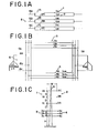
- Figs. 1 (A) to 1 (C) show an idealized common suspension multi line system to which the present invention has been applied.
- 1 A, 1 B, 1 C, 2A, 2B, 2C are 187 KV to 500 KV very high voltage transmission lines (henceforth referred to as the inducting system), and 5A, 5B, and 5C are buses for the very high voltage transmission lines whose phases are indicated by A, B and C respectively.
- a first circuit 1 comprises the lines 1 A, 1 B and 1 C
- a second circuit 2 comprises the lines 2A, 2B and 2C.
- I 1A , I 1B , and I 1C indicate the currents of A, B and C phases.
- 3a, 3b, 3c, 4a, 4b, and 4c are 66 KV to 154 KV high resistance earthing system transmission lines (henceforth referred to as the inducted system), and 6a, 6b, and 6c are buses for the phases a, b, and c respectively of the high resistance grounding system transmission lines.
- a third circuit 3 comprises the lines 3a, 3b and 3c, and a fourth circuit comprises the lines 4a, 4b, and 4c.
- I ath , I bth , and I cth are the circulation currents in phases A, B, and C respectively, flowing from the third circuit 3 to the fourth circuit 4 because of the induction of the induction system in Fig. 1 (A).
- V o A is in the same way the zero phase vertical voltage drop generated at power station S A by induction.
- the power station on the side of the bus 6 of the inducted circuit is termed S AI and that on the opposite side is termed S B .
- the neutral points of S A and S B are each connected to ground through neutral point grounding resistances R NA , R NB .
- Fig. 1 (C) shows how the inducting and inducted systems of Figs. 1 (A) and 1 (B) may be supported together by a single steel tower 51.
- the lines 1A to 1C and 2A to 2C of the inducting system are in reverse phase distribution, and the lines 3a to 3c and 4a to 4c of the inducted system are in inphase distribution.
- the currents flowing phases A, B, and C of the circuits 1 and 2 will be called I 1A , I 1B , I 1C , I 2A , I 2B , and I 2C .
- I 1A , I 1B , I 1C , I 2A , I 2B , and I 2C Letting the electromagnetic induction voltages induced in each phase in the circuits 3 and 4 by the currents in the circuits 1 and 2 be V 3ma, V 3mb , V 3mc , V 4ma , V 4mb , and V4mc, we have:
- Equation (5) (M 3a.1A ) is the mutual inductance between conductors 3A and 1 A.
- circuits 3 and 4 are symmetrical to right and left:
- equation (16) Substituting equation (16) into equations (1) and (2), equations (1) and (2) become:
- I ath , I bth , I cth are proportional to the currents of 1 and 2 of the inducting system, and this coefficient of proportionality is given by the following when the inducting system is operating:
- the constants of proportionality K a , K b , and K c of I ath , I bth , and I cth and the currents I of the inducting system are determined by the distribution of the conductors and the operating state of the inducting system.
- I oth is proportional to the currents of the circuits 1 and 2 of the inducting system, and the constant of proportionality is given as follows, when the inducting system is in the operating state:
- the constant of proportionality K of I oth and the current I of the inducting system is determined by the conductor distribution and the operating state of the inducting system.
- This line to earth zero phase circulation current I g oth flows through the neutral point earthing resistances R NA and R NB of the power stations S A and S B , and the zero phase vertical voltages V A 0 and V B 0 generated at power stations S A and S B , are given by:
- V A 0 and V B 0 are relative to earth potential. Eliminating I 1 and I 2 from equations (29) and (38), we get the following.
- V A 0 and l oth are proportional, and the constant of proportionality, K is determined by the distribution of the conductors and the operating state of the inducting system.
- K is determined by the distribution of the conductors and the operating state of the inducting system.
- V B 0 When the inducted system is normal, V A 0 , V B 0 , I g oth, and I oth are generated irrespective of failures, and by these erroneous operation or erroneous non-operation of a grounding protective relay can occur, and thus it is necessary to compensate for this.
- the following facts have been established:
- the present invention is based on the above characteristics (1) to (4), and an embodiment of the common suspension multi-line grounding protective relay of the present invention is explained with reference to Figs. 2 to 5.
- Figs. 2A and 2B show a common suspension multi-line earthing protective relay according to this embodiment, and portions which are the same as portions of Fig. 1 are shown with the same reference numerals.
- Fig. 2(A) there is shown a common suspension multi-line grounding protective relay according to the present invention.
- a T-branch load 7 is connected to power transmission lines 3a to 3c of a third power transmission circuit.
- a current detector 8 is provided between the third power transmission circuit 3 and a fourth power transmission circuit 4.
- the current detector 8 comprises current transformers 37a to 37c which are, connected to lines 3a to 3c respectively, current transformers 47a to 47c and current difference detectors 50a to 50c connected as a subtraction circuit to determine the differences in phases A, B, and C between the lines 3a, 3b, 3c and the lines 4a, 4b and 4c.
- Circuit breaker sections 9A and 9B are provided in the third and fourth power transmission circuits.
- the circuit breaker section 9A consists of circuit breakers 9a to 9c connected as shown.
- the circuit breaker section 9B consists of circuit breakers 9d to 9f connected as shown.
- the common suspension multi-line grounding protective relay comprises, substantially, elements numbered 10 to 25 in Figs. 2(A) and 2(B).
- the reference numeral 10 is a first data converter which samples at a fixed frequency the current S, from the current detecting section 8, in other words the inter-line differential currents I as , I bs , and I cs and performs analog to digital conversion on them.
- Fig. 2(A) 11 is a voltage detecting section, and consists of, mounted on the buses 6a to 6c, a zero phase voltage detector 12, and a phase voltage detector 13.
- 2(B) 14 is a second data converter which inputs the detected signal S 2 of the voltage detector 12, in other words the zero phase voltage V OF , and in synchronism with the above mentioned first data converter 10 samples the zero phase voltage V OF at a fixed frequency, and performs analog to digital conversion on it.
- a first calculating section which inputs the grounding fault detection signal Sg from a first decision section 19, the output S 3 of the first data converter 10, and the output S 5 of the filter 5, and when the first decision section 19 determines that the system is normal, performs at a sampling frequency or a sub-multiple of the sampling frequency the calculation of the ratio of the magnitudes and the phase differences between R a , R b , and R c which are constants of each phase and are required to calculate the zero phase circulation current in the grounding fault, and then calculates R a , R b , R c .
- 17 is a third calculating section which inputs the output signal S 9 of the first decision section 19, the output S 3 of the first data converter 10, and the output S 4 of the second data converter 14, when the first decision section 19 determines that the system is normal, when an earthing fault occurs performs calculation of the equation (66) described below to determine the zero phase voltage at the same sampling frequency or sub-multiple of the sampling frequency of the above mentioned first calculating section, and calculates the ratio of the sizes and the phase difference K A 0 of the zero phase voltage S 3 output by the above mentioned second data converter, and the zero phase component of the inter-line differential current S 3 .
- the first decision section 19 determines the existence of an grounding fault.
- 20 is a third data converter which converts the output of the voltage detector system 13 to a digital quantity, and outputs the digital quantity to a second decision section 21.
- the 22 is a first selection section which inputs the output S 8 of the second calculation section 18, in other words, the calculation values for calculating the zero phase circulation currents in an earthing fault according to the phase which is earthed and the earthing phase detection signal S 11 from the second decision section 21, and: if phase a is earthed, calculating the zero phase circulation current from R a and the inter-line differential currents for phases b and c, if phase b is earthed, calculating the zero phase circulation current from Rb and the inter-line differential currents for phases a and c; and if phase c is earthed, calculating the zero phase circulation current from R e and the inter-line differential currents from phases a and b.
- a fourth calculating section which inputs the zero phase circulation current, which is the output S 12 of the first selection section, and K A 0 which is the output S 7 of the third calculating section, and by performing a calculation of equation (67) described below, and corrects the zero phase circulation currents by using the ratio of sizes and phase difference K A 0 , to find the zero phase vertical voltage V A 0 when grounding fault occurs.
- 24 is a first compensating section which inputs the output S 3 of the first data converter, the output S 4 of the second data converter, the output S 4 of the first selection section, and the output S 12 of the fourth calculating section, and compensates for the zero phase circulation current including the zero phase component of the inter-line differential current and the zero phase vertical voltage, including the zero phase voltage which is the output S 4 of the second data converter, using equations (74) and (75) described below.
- 25 is an earthing circuit selection section which inputs S 14 , the zero phase component of the inter-line differential current and zero phase voltage, of which the zero phase circulation current and zero phase vertical voltage have been compensated for in the first compensating section, and selects the earthing circuit.
- the distributions of the circulation currents I ath , I bth , and I cth , the a-phase grounding currents I 3 F and I 4 F and load currents I 3 a , I 3 b , I 3 c , I 4 a , I 4 h , and I 4 p are shown.
- the circulation currents in each phase circulating from circuit 3 to circuit 4 are I ath I bth , and I cth and the load currents flowing in each phase in circuit 3 and circuit 4 are respectively I 3 a , I 3 b , I 3 c , I 4 a , I 4 b , and I 4 c .
- the grounding current flowing in each phase a in circuit 3 is I 3 F ; the grounding current flowing in phase a of circuit 4 is 1 4 F .
- a grounding protective relay according to the present invention is installed in power station S A in the common suspension system described below and shown in Figs. 2A and 2B.
- the load currents I 3 a , I 3 b , and I 3 c of circuit 3 and the load currents I 4 a , I 4 b , and I 4 c are not in equilibrium.
- a filter 15 performs the calculation of equation (43). Because in I bs , and I cs no current is generated by earthing:
- equation (54) becomes:
- I oth (o) on the right-hand side of equation (58) is equal to 1/2 of the zero phase component of I as (o), I bs (o), and I cs (o).
- phase c when phase c is earthed, from the inter-line differential currents of the normally operating phases I' as and I' bs :
- I' oth is the zero phase circulation current derived by selecting the calculation results of equation (60), (61), or (63), according to the phase which is earthed, then when a grounding fault occurs, the zero phase vertical voltage V AI 0 is obtained from equation (65) as follows:
- V F shows the zero phase voltage generated by a grounding fault.
- IF is the grounding circuit selection relay input current
- V F is the voltage input. Compensation for I o , th , and V o A' from the calculation of equations (74) and (75), is performed by the first compensating section 24.
- the selection, according to IF and V F of the earthing circuit is performed by the earthing circuit selection section 25.
- circuit breaker 9a, 9b, 9c, 9d, 9e, or 9f is tripped.
- E a , E b , and E c are measured by the voltage detector 13 of Fig. 2B. These are converted to digital quantities in the third data converter 20 of Fig. 2B, and input to the second decision section 21, and then a test is made as to which of the following relations hold:
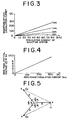
- Fig. 5 a vector diagram of the voltage for each phase is shown by a.-.-.- line, for the case when phase a is earthed, and ignoring induction for a very high voltage transmission line.
- the solid lines show a vector diagram for normal operating conditions. If the magnitude of the voltage of each phase under normal operating conditions is taken as E, and phase a is taken as a base vector, when phase a is earthed, the voltages of each phase are found as follows:
- Figs. 6A and 6B show an example flowchart of processing when the principle of the present invention is implemented by a microcomputer. Only the most important parts of the processing are shown; the initialising portion to calculate R a , R b , and R c is omitted.
- the earthed phase is detected from the inter-line differential currents.
- the voltage E a , E b , E c , the inter-line differential currents l as , I bs , and I cs for phases a, b, and c, and the zero phase voltage V OF which have been measured by current transformers and voltage transformers, are sampled at a fixed frequency, and analog to digital conversion is carried out. This corresponds to the first and second data converters.
- I I indicates an absolute value
- block B 5 if a decision is made that the system is operating normally, in block B 7 , at either the sampling frequency or a sub-multiple of the sampling frequency, the values I as , l bs , I cs , and V OF which were converted to digital quantities in block B 2 , are input, and the values R a , R b , R c , and K o A of expressions (59), (62), (64), and (66) described above, are calculated. The frequency of calculation is determined by block B 6 .
- Block B 7 corresponds to the first and third calculating sections 16 and 17. From block B 7 a return is made to block B 2' and the next measured values are sampled.
- Blocks B 11 , B 12 , and B 13 input the signals output by blocks B 8 to B 10 for each of phases a, b, and c to be earthed, and according to the phase which is earthed, selects the expression found in block B 4 for the zero phase circulation current I oth .
- the calculated expression used as the zero phase circulation current will be the aforesaid expression (60) if phase a is earthed, the aforesaid expression (61) if phase b is earthed, and the aforesaid expression (63) if phase c is earthed. These blocks correspond to the first selection section 22.
- Block B 14 inputs the zero phase circulation current found in blocks B 11 to B 13 , and K o A found in block B,, and calculating the above mentioned expression (67), derives the zero phase vertical voltage V o A. This corresponds to the fourth calculating section 23.
- Block B 15 inputs I as , I bs , I cs , and V OF which were converted to digital quantities in block B 2 , the zero phase vertical voltage found in block B 141 and the zero phase circulation current derived in blocks B" to B 131 and using expressions (74) and (75), described above, corrects the zero phase circulation current and zero phase vertical voltage for the superimposed inter-line differential current zero phase component I as +I bs +I cs , and zero phase component V OF . This corresponds to the first compensating section 24.
- Block B 16 inputs the inter-line differential current zero phase component which was corrected for the zero phase circulation current in block B 15 , and the zero phase voltage which was corrected for the zero phase vertical voltage in block B 15 , and selecting the line which has been earthed, corresponding to the earthed line sends a circuit breaker trip signal. This corresponds to the earthing circuit selection section 25.
- the present invention makes use of the fact that the inter-line circulation currents I ath' I bth , and I cth of phases a, b, and c of the inducted system, the zero phase circulation current I oth , and the zero phase vertical voltage V o A, are proportional to the flow in the inducting system; in other words, that the relation with I ath , I bth' I cth, I oth' and V o A is one of fixed ratio proportionality irrespective of the magnitude and phase of the flow in the inducting system.
- the constants R a , R b , R c , and K o A are automatically adjusted, and using these constants, for each pair of phases after eliminating the positive phase component from the inter- line differential current, its magnitude and phase are corrected and the phase, which is earthed, is detected.
- the zero phase circulation current, and zero phase vertical voltage are found and compensated.
- the effect of zero phase circulation currents and zero phase vertical voltages is made very small, and a grounding protective relay which can detect grounding accidents with high accuracy, can be obtained, with most efficacious results.
- the present invention is not only applicable to a common suspension system of a very high voltage system and a high resistance grounding system, but may also be applied to a common suspension system of two high resistance grounding systems, in order to provide grounding protection.
Landscapes
- Engineering & Computer Science (AREA)
- Power Engineering (AREA)
- Emergency Protection Circuit Devices (AREA)
Description
- The present invention relates to a protective device for a power supply system, and particularly to a grounding protective relay which compensates for zero phase circulation current between lines and zero phase vertical voltage drops generated by induction in a common suspension multi-line system in which a common suspension multi-line high resistance grounding system (including a Petersen Coil grounding system) has a T-branch load between two parallel lines.
- In electrical transmission systems with very high voltage transmission lines and common suspension high resistance grounding systems, because the very high voltage transmission lines are arranged in non-crossover suspension, and reverse phase distribution, the flow of current in the very high voltage transmission line induces zero phase circulation currents between lines (henceforth referred to simply as zero phase circulation currents) and zero phase vertical voltage drops, and for this reason the grounding protective relay operates erroneously or fails erroneously to operate. Because of this, it is necessary to compensate for zero phase circulation currents and zero phase vertical voltage drops.
- The present invention is a result of considering the above mentioned points, and it is the object of the present invention to provide a grounding protective relay which makes the influence of zero phase circulation currents and zero phase vertical voltage drops as small as possible, with the capability of accurately detecting grounding faults.
- It is known from CH Specification No. 373,806 to provide a circuit arrangement for the detection of earthing faults and the removal of earth short circuits on double three-phase transmission lines, wherein distance relays are provided whose impedance measuring elements receive, by way of transformers, current and voltages from both lines, the current or a voltage proportional to the current from each line being improved by means of a first comparison relay such that when a predetermined adjustable threshold value of the relay is exceeded, a contact thereof is actuated to supply a neutral current, or a voltage proportional to the neutral current, from the line running parallel to the faulty line to the current part of the impedance measuring element associated with the first line, and a second comparison relay being used and having an associated contact for connecting the same electrical parameters of the circuit of the faulty line to the current part of the impedance measuring element associated with the second line; the response value of the second comparison relay, which is also adjustable being the reciprocal of the response value of the first comparison relay.
- According to the present invention there is provided a common suspension grounding protective relay, comprising:
- current detector means for detecting the currents in at least three phases of respective high voltage parallel transmission lines of two power transmission circuits, and for outputting the interline differential currents between each two phases of said at least three phases; characterised in that there is provided
- filter means inputting said inter-line differential current between each two phases of the two power transmission circuits from said current detector means and for eliminating from the inter-line differential current of said each two phases the positive phase component;
- first calculating means for calculating the zero phase component from the inter-line differential currents detected by said current detector means and for calculating the ratio of the magnitudes and the phase difference between said zero phase component and the output of said filter means;
- second calculating means for correcting the outputs of said filter means from the ratio of the magnitudes and phase difference derived by said first calculating means;
- grounded phase detector means for carrying out detection of the phase which is grounded;
- selection means for selecting a derivation result from said second calculating means according to the phase which is grounded; and
- zero phase current selection means for selecting the zero phase circulation current from said second calculating means by said selection means.
- The invention will now be further explained and one particular relay arrangement in accordance with the present invention will be described, by way of an example, with reference to the accompanying drawings in which:
- Figs. 1 (A) to 1 (C) show an idealized common suspension multi-line system;
- Fig. 2(A) shows an electric circuit diagram of a common suspension multi-line using a grounding protective relay according to the present invention;
- Fig. 2(B) shows a block diagram of a common suspension multi-line system grounding protective relay according to the present invention;
- Fig. 3 shows the relations between the circulation currents found in the idealized system of Fig. 1 and the flow in the inducting system;
- Fig. 4 shows the relation between the zero phase vertical voltage and the zero phase circulation current;
- Fig. 5 is a vector diagram of the voltage for each phase when phase a is grounded; and
- Figs. 6(A) and 6(B) show a flow diagram of an implementation of the principle of the present invention using a microcomputer.
- Figs. 1 (A) to 1 (C) show an idealized common suspension multi line system to which the present invention has been applied. In Fig. 1 (A), 1 A, 1 B, 1 C, 2A, 2B, 2C are 187 KV to 500 KV very high voltage transmission lines (henceforth referred to as the inducting system), and 5A, 5B, and 5C are buses for the very high voltage transmission lines whose phases are indicated by A, B and C respectively. A
first circuit 1 comprises thelines 1 A, 1 B and 1 C, and asecond circuit 2 comprises thelines third circuit 3 comprises thelines lines third circuit 3 to thefourth circuit 4 because of the induction of the induction system in Fig. 1 (A). Vo A is in the same way the zero phase vertical voltage drop generated at power station SA by induction. - The power station on the side of the
bus 6 of the inducted circuit is termed SAI and that on the opposite side is termed SB. The neutral points of SA and SB are each connected to ground through neutral point grounding resistances RNA, RNB. - Fig. 1 (C) shows how the inducting and inducted systems of Figs. 1 (A) and 1 (B) may be supported together by a
single steel tower 51. The lines 1A to 1C and 2A to 2C of the inducting system are in reverse phase distribution, and thelines 3a to 3c and 4a to 4c of the inducted system are in inphase distribution. W, D, D', d, and H show the distribution of the lines; for example W=8m, D=8m, D'=8.5m, d=3m, and H=20m. - The currents flowing phases A, B, and C of the
circuits circuits circuits 

- Here Im is the common supported length in kilometres of the inducting and inducted systems, w is the angular frequency of the system, and () is used to represent a matrix.


- (L31) mutual inductance of the
circuits - (L32) mutual inductance of the
circuits - (L41) mutual inductance of the
circuits - (L42) mutual inductance of the
circuits 

- In equation (5) (M3a.1A) is the mutual inductance between conductors 3A and 1 A.

- D3a.IA: distance (m) between the
conductors 3a and 1a; - He: equivalent ground surface depth (m).
- Letting the currents in phases a, b, and c of the
circuits 


- (L33)=self and mutual inductance of
circuit 3. - (L34)=mutual inductance of the
circuits - (L44)=self and mutual inductance of
circuit 4. - (L43)=mutual inductance of 4 and 3.


- M3a,3a=self inductance of
conductor 3a. - M3a,3a=M4a,4a.

- Because the
circuits 

- Substituting (11) and (12) into (7) and (8), (7) and (8) become:


- From (14), the currents Iath and Ibth, Icth of phases a, b and c in 3 and 4 of the inducted systerr caused by electromagnetic induction from the inducting system, are given by:

- If we assume that the currents flowing in the inductance system are in equilibrium,


- Substituting equation (16) into equations (1) and (2), equations (1) and (2) become:

- Substituting equation (17) into equation (15):


- As will be seen from equations (20), (21), and (22), Iath, Ibth, Icth are proportional to the currents of 1 and 2 of the inducting system, and this coefficient of proportionality is given by the following when the inducting system is operating:


- When both
circuits 
- When only 1 of the inducting system is operating, setting I1=I and I2=0, and substituting into equations (20) to (22):

- When only
circuit 2 of the inducting system is operating, setting I1=0 and I2=I, and substituting into equations (20) to (22):
- As will be seen from equations (26) to (28), the constants of proportionality Ka, Kb, and Kc of Iath, Ibth, and Icth and the currents I of the inducting system, are determined by the distribution of the conductors and the operating state of the inducting system.
- Again, from equation (18), the zero phase component of Iath, Ibth, and Icth, in other words, the zero phase circulation current loth is given by:


- As will be seen from equation (29), Ioth is proportional to the currents of the
circuits 
- With this representation, when both
circuits 
- When 1 only is operating:

- When
circuit 2 only is operating:
- As will be seen from equations (30) to (33), the constant of proportionality K of Ioth and the current I of the inducting system, is determined by the conductor distribution and the operating state of the inducting system.
- Substituting equations (11) and (12) into equations (7) and (8):
- (jwlm((L33)+(L34))+2(RNA+RNB)E) · ((I3)+(I4))=-(V3m)-(V4m) (34)
- Substituting equation (16) into equations (1 and (2):

- Substituting equation (34) into equation (35), (I3)+(I4) is given by:

- (I3)+(I4) is the current circulated in the inducted system and the earth by the electromagnetic induction of the inducting system, and this zero phase component, or in other words the inter-earth zero phase vertical circulation current ¡9 0th is given by:

- This line to earth zero phase circulation current Igoth flows through the neutral point earthing resistances RNA and RNB of the power stations SA and SB, and the zero phase vertical voltages VA 0 and VB 0 generated at power stations SA and SB, are given by:


- Here VA 0 and VB 0 are relative to earth potential. Eliminating I1 and I2 from equations (29) and (38), we get the following.
- When both
circuits 

- When
only circuit 1 of the inducting system is operating, setting I2=0:

- When
only circuit 2 of the inducting system is operating:

- As will be seen from equations (40) to (42), VA 0 and loth are proportional, and the constant of proportionality, K is determined by the distribution of the conductors and the operating state of the inducting system. The same can be said of VB 0. When the inducted system is normal, VA 0, VB 0, Igoth, and Ioth are generated irrespective of failures, and by these erroneous operation or erroneous non-operation of a grounding protective relay can occur, and thus it is necessary to compensate for this. Above, the following facts have been established:
- (1) the zero phase interline circulation currents Iath, Ibth, and Icth of phases a, b, and c are proportional to the flow in the inducting system. Proved by equations (23) to (28).
- (2) the interline zero phase circulation current Ioth and the flow in the inducting system are proportional. Proved by equations (29) to (33).
- (42). (3) the zero phase vertical voltages VA 0, VB 0, and Ioth are proportional. Proved by equations (40) to
- (4) the constants of proportionality (1), (2), and (3) are fixed properties of the system and are each determined by the arrangement of conductors and the operating state of the inducting system.
- The present invention is based on the above characteristics (1) to (4), and an embodiment of the common suspension multi-line grounding protective relay of the present invention is explained with reference to Figs. 2 to 5.
- Figs. 2A and 2B show a common suspension multi-line earthing protective relay according to this embodiment, and portions which are the same as portions of Fig. 1 are shown with the same reference numerals. In Fig. 2(A), there is shown a common suspension multi-line grounding protective relay according to the present invention. As shown in Fig. 2(A), a T-branch load 7 is connected to
power transmission lines 3a to 3c of a third power transmission circuit. Acurrent detector 8 is provided between the thirdpower transmission circuit 3 and a fourthpower transmission circuit 4. Thecurrent detector 8 comprises current transformers 37a to 37c which are, connected tolines 3a to 3c respectively,current transformers 47a to 47c andcurrent difference detectors 50a to 50c connected as a subtraction circuit to determine the differences in phases A, B, and C between thelines lines Circuit breaker sections circuit breaker section 9A consists of circuit breakers 9a to 9c connected as shown. Thecircuit breaker section 9B consists ofcircuit breakers 9d to 9f connected as shown. - The common suspension multi-line grounding protective relay comprises, substantially, elements numbered 10 to 25 in Figs. 2(A) and 2(B). In Fig. 2(B), the
reference numeral 10 is a first data converter which samples at a fixed frequency the current S, from the current detectingsection 8, in other words the inter-line differential currents Ias, Ibs, and Ics and performs analog to digital conversion on them. In Fig. 2(A) 11 is a voltage detecting section, and consists of, mounted on thebuses 6a to 6c, a zero phase voltage detector 12, and aphase voltage detector 13. In Fig. 2(B) 14 is a second data converter which inputs the detected signal S2 of the voltage detector 12, in other words the zero phase voltage VOF, and in synchronism with the above mentionedfirst data converter 10 samples the zero phase voltage VOF at a fixed frequency, and performs analog to digital conversion on it. 15 is a filter which inputs the digital values S3, which are Ias, Ibs, and Ics, output by thefirst data converter 10, and calculates from the inter-line differential currents between each two phases, Ias-aIbs, Ibs-aIcs, and Ics-aIas (where a=ej2/3 π), thus eliminating the positive phase component. 16 is a first calculating section, which inputs the grounding fault detection signal Sg from a first decision section 19, the output S3 of the first data converter 10, and the output S5 of the filter 5, and when the first decision section 19 determines that the system is normal, performs at a sampling frequency or a sub-multiple of the sampling frequency the calculation of the ratio of the magnitudes and the phase differences between Ra, Rb, and Rc which are constants of each phase and are required to calculate the zero phase circulation current in the grounding fault, and then calculates Ra, Rb, Rc. 17 is a third calculating section which inputs the output signal S9 of the first decision section 19, the output S3 of the first data converter 10, and the output S4 of the second data converter 14, when the first decision section 19 determines that the system is normal, when an earthing fault occurs performs calculation of the equation (66) described below to determine the zero phase voltage at the same sampling frequency or sub-multiple of the sampling frequency of the above mentioned first calculating section, and calculates the ratio of the sizes and the phase difference KA 0 of the zero phase voltage S3 output by the above mentioned second data converter, and the zero phase component of the inter-line differential current S3. 18 is a second calculating section which inputs the output S5 of the above mentioned filter 15, and the constants Ra, Rb, and Re of the below described equations (59), (62), and (64) necessary for derivation of the zero phase circulation currents when an earthing fault occurs and which are the output S6 of the above mentioned first calculating section, and performs necessary calculation for derivation of the zero phase circulation currents when an earthing fault occurs. Thefirst decision section 19 determines the existence of an grounding fault. 20 is a third data converter which converts the output of thevoltage detector system 13 to a digital quantity, and outputs the digital quantity to asecond decision section 21. 22 is a first selection section which inputs the output S8 of thesecond calculation section 18, in other words, the calculation values for calculating the zero phase circulation currents in an earthing fault according to the phase which is earthed and the earthing phase detection signal S11 from thesecond decision section 21, and: if phase a is earthed, calculating the zero phase circulation current from Ra and the inter-line differential currents for phases b and c, if phase b is earthed, calculating the zero phase circulation current from Rb and the inter-line differential currents for phases a and c; and if phase c is earthed, calculating the zero phase circulation current from Re and the inter-line differential currents from phases a and b. 23 is a fourth calculating section, which inputs the zero phase circulation current, which is the output S12 of the first selection section, and KA 0 which is the output S7 of the third calculating section, and by performing a calculation of equation (67) described below, and corrects the zero phase circulation currents by using the ratio of sizes and phase difference KA 0, to find the zero phase vertical voltage VA 0 when grounding fault occurs. 24 is a first compensating section which inputs the output S3 of the first data converter, the output S4 of the second data converter, the output S4 of the first selection section, and the output S12 of the fourth calculating section, and compensates for the zero phase circulation current including the zero phase component of the inter-line differential current and the zero phase vertical voltage, including the zero phase voltage which is the output S4 of the second data converter, using equations (74) and (75) described below. 25 is an earthing circuit selection section which inputs S14, the zero phase component of the inter-line differential current and zero phase voltage, of which the zero phase circulation current and zero phase vertical voltage have been compensated for in the first compensating section, and selects the earthing circuit. S151 the output of this earthing circuit selection circuit, is an earthing circuit trip signal, and by this signal thegrounding circuit breakers - In an earthing protection relay of the above construction, as one example, the distributions of the circulation currents Iath, Ibth, and Icth, the a-phase grounding currents I3 F and I4 F and load currents I3 a, I3 b, I3 c, I4 a, I4 h, and I4 p are shown.
- Here, the circulation currents in each phase circulating from
circuit 3 tocircuit 4 are Iath Ibth, and Icth and the load currents flowing in each phase incircuit 3 andcircuit 4 are respectively I3 a, I3 b, I3 c, I4 a, I4 b, and I4 c. The grounding current flowing in each phase a incircuit 3 is I3 F; the grounding current flowing in phase a ofcircuit 4 is 14 F. - To explain the derivation of the zero phase circulation current Ioth when there is a grounding fault, a grounding protective relay according to the present invention is installed in power station SA in the common suspension system described below and shown in Figs. 2A and 2B. In the case where the induced system has a T-branch load 7, as shown in the figure, the load currents I3 a, I3 b, and I3 c of
circuit 3, and the load currents I4 a, I4 b, and I4 c are not in equilibrium. In order to avoid the influence of the load currents and to measure only the circulation currents, if for example a-phase is earthed, from the inter- line differential currents Ibs and Ics of phases b and c, by performing the following calculation, the positive phase component is eliminated:
- A
filter 15 performs the calculation of equation (43). Because in Ibs, and Ics no current is generated by earthing:

- If we suppose that the load currents are in equilibrium, we have:


- Ibs-a Ics=I3 b-I4 b+2ibth-a(I3 c-I4 c+2Icth)=(I3 b-aI3 c)-(I4 b-aI4 c)+2(Ibth-aIcth) (48)
- To reiterate the related equations for equations (23), (24), (25), and (30) of the first common 5 suspension idealised system:


- Here (o) shows a value for a normal operating time. A graphical representation of equations (50) Substituting equations (51) to (53) into equation (49):

- Here ' is used to indicate values when there is an a-phase earthing, and at this time, setting the current of the inducting system as I', and the zero phase circulation current as I'oth, from equation (53):

- Again, when phase a is earthed, equation (54) becomes:

- Eliminating 1(0) from equations (53) and (54), we have:

- Substituting equations (56) and (57) into equation (55), I'oth can be obtained from:

- Ioth(o) on the right-hand side of equation (58) is equal to 1/2 of the zero phase component of Ias(o), Ibs(o), and Ics(o). Setting the first item of the right hand side of equation (58) to Ra, we have:

- Substituting equation (59) into equation (58):

- As above, by first determining Ra shown in equation (59), when the system is normal, then when phase a is earthed, from the inter-line differential currents I'bs and I'cs of the normal phases, from equation (60), I'oth can be determined.
- In the same way, when phase b is earthed, from the inter-line differential currents I'as and I'bs of the normally operating phases, we have:


- From equation (61) I'oth can be found.
- In the same way, when phase c is earthed, from the inter-line differential currents of the normally operating phases I'as and I'bs:


- From equation (63) I'oth can be found. The calculation of Ra, Rb, and Rc of equations (59), (62), and (64), is carried out by the first calculating
section 16, and the calculation of equations (60), (61), and (63) is performed by the second calculatingsection 18. According to the phase which is earthed, the grounding circulation current is selected from the calculation values of equations (60), (61), and (63) by the first selection section. Next the derivation of the zero phase vertical voltage VA O will be described. As shown by equations (40), (41), and (42), VA 9 and loth are proportional. In the common suspension idealised system of Fig. 1, equations (40) to 142) are shown graphically in Fig. 4. - To write equation (40) again:

- If we let the values of VA and Ioth when the inducted system is operating normally, be VA 0(o) and Ioth(o) respectively, at this time VA 0 is equal to the measured value of the zero phase voltage VOF. Finding K0 from equation (65), we have:―

- If I'oth is the zero phase circulation current derived by selecting the calculation results of equation (60), (61), or (63), according to the phase which is earthed, then when a grounding fault occurs, the zero phase vertical voltage VAI 0 is obtained from equation (65) as follows:

- The calculation of equation (66) is performed by the third calculating
section 17, and the calculation of equation (67) is performed by the fourth calculatingsection 23. - Above, the derivation of I'oth and VA' 0 when a grounding fault occurs, has been described. Next, taking the case where phase a is earthed as an example, the method of compensating for I'oth and VA' 0 in the grounding circuit selection relay, will be described. When phase a is earthed, the inter-line differential currents Ia,s, Ib,s, and Ic,s of phases a, b, and c, and the zero phase voltage VOF are given, by referring to Fig. 2A by:


- In equation (71), VF, shows the zero phase voltage generated by a grounding fault. Taking as the ordinary grounding circuit selection relay current input, the zero phase component Io of the inter-line differential current, and as the voltage input, the zero phase voltage Vo of the measured quantity:




- (Here ' represents a quantity when a grounding fault occurs).
- As will be clear from equations (72) and (73), as well as the component IF.1-IF2 of the current input Io, from the earthing, there is added twice the zero phase circulation current 2Io,th; as well as the component VF, of the voltage input Vo from the grounding, there is added the zero phase vertical voltage VoA'. Because of these terms 2Io,tn and VoA', the grounding circuit selection relay can erroneously operate or erroneously fail to operate: thus it is necessary to compensate for these terms. When phase a is grounding, obtaining Io,th from equation (60), and obtaining VoA', from equation (67), these values are compensated for by the following equation:


- In equation (74), IF is the grounding circuit selection relay input current, and in equation (75), VF is the voltage input. Compensation for Io,th, and VoA' from the calculation of equations (74) and (75), is performed by the first compensating
section 24. The selection, according to IF and VF of the earthing circuit is performed by the earthingcircuit selection section 25. Thus, according to signal S15 from the earthingcircuit selection section 25, in thecircuit breaker section circuit breaker - When the system is operating normally, the calculation results of equations (60), (61 and (63) are all equal to the zero phase circulation current, but when a grounding fault occurs, because a grounding current is generated in the phase which is earthed, the values of expressions (60), (61), and (63) are not equal. By comparing the calculation values of the expressions (60) and (61), in relation (76):

section 18, and the detection of a grounding fault, by testing whether relation (76) holds or not, is performed by thefirst decision section 19. - In order to select the calculation value of equation (60), (61), or (63), according to the phase which is earthed, and thus to derive the zero phase circulation current, it is necessary to determine the phase which is earthed.
- A method of detecting the phase which is earthed from the voltages Ea, Eb, and Ec of phases a, b, and c is now described. Ea, Eb, and Ec are measured by the
voltage detector 13 of Fig. 2B. These are converted to digital quantities in the third data converter 20 of Fig. 2B, and input to thesecond decision section 21, and then a test is made as to which of the following relations hold:


- Where e is a sufficiently small positive constant, and I and I indicates absolute value.
- In Fig. 5 a vector diagram of the voltage for each phase is shown by a.-.-.- line, for the case when phase a is earthed, and ignoring induction for a very high voltage transmission line. The solid lines show a vector diagram for normal operating conditions. If the magnitude of the voltage of each phase under normal operating conditions is taken as E, and phase a is taken as a base vector, when phase a is earthed, the voltages of each phase are found as follows:


- Substituting equations (80), (81), and (82) into relations (77), (78), and (79), we get:


- After choosing a sufficiently small positive value for the constant e, relation (77) only will hold, and relations (78) and (79) will not hold.
- In the same way, when phase b is earthed, relation (78) only will hold, and relations (77) and (79) will not hold. Again, when phase c is earthed, relation (79) only will hold, and relations (77) and (78) will not hold. Therefore, from which of relations (77) to (79) holds the earthed phase can be detected. Which of relations (77) to (79) hold for each phase being earthed, is shown in Table.

- Status of relations (77), (78), and (79) for different earthed phases.
- Yes: holds; No: does not hold.
- Figs. 6A and 6B show an example flowchart of processing when the principle of the present invention is implemented by a microcomputer. Only the most important parts of the processing are shown; the initialising portion to calculate Ra, Rb, and Rc is omitted. In the example shown the earthed phase is detected from the inter-line differential currents. In Fig. 6 in block B2 the voltage Ea, Eb, Ec, the inter-line differential currents las, Ibs, and Ics for phases a, b, and c, and the zero phase voltage VOF, which have been measured by current transformers and voltage transformers, are sampled at a fixed frequency, and analog to digital conversion is carried out. This corresponds to the first and second data converters.
- In block B3, by selecting the inter-line differential currents for two phases from the inter-line differential currents for all phases, Ias, Ibs, and Ics, the positive phase components are eliminated. When the positive phase component is eliminated from the inter-line differential current for phases a and b, or b and c, or c and a, the result is Iab, Ibc, or Ica. This corresponds to the
filter 15. - In block B4, the above described expressions (60), (61), and (63) are calculated from Ra, Rb, and Rc found in block B7 described below, and lab, Ibc, and Ica found in block B3. This corresponds to the second calculating
section 18. - In block B5, the calculation results of the above mentioned relations (60) and (61) found in block B4 are substituted into the above mentioned relation (76); to write this relation in a different way:

- Where I I indicates an absolute value.
- If the right-hand side of the relation is smaller than the sufficiently small constant d, then if relation (86) is determined to hold, the system will be in the normal operating state. If this is not the case, then a grounding fault has occurred. This corresponds to the
first decision section 19. - In block B5, if a decision is made that the system is operating normally, in block B7, at either the sampling frequency or a sub-multiple of the sampling frequency, the values Ias, lbs, Ics, and VOF which were converted to digital quantities in block B2, are input, and the values Ra, Rb, Rc, and KoA of expressions (59), (62), (64), and (66) described above, are calculated. The frequency of calculation is determined by block B6. Block B7 corresponds to the first and third calculating
sections - If in block B5, it is determined that an earthing failure has occurred, the phase which has been earthed is determined in blocks B8, B9, and B10. These blocks input the results of blocks B3 and B4; to express relations (77), (78), and (79) differently, we have:


- Here e is a sufficiently small constant. Relations (87) to (89) are calculated, and if relation (87) holds, then phase a is earthed, if relation (88) holds, then phase b is earthed, and if relation (89) holds, then phase c is earthed. Blocks B8, B9, and B10 correspond to the
second decision section 21. - Blocks B11, B12, and B13 input the signals output by blocks B8 to B10 for each of phases a, b, and c to be earthed, and according to the phase which is earthed, selects the expression found in block B4 for the zero phase circulation current Ioth. The calculated expression used as the zero phase circulation current will be the aforesaid expression (60) if phase a is earthed, the aforesaid expression (61) if phase b is earthed, and the aforesaid expression (63) if phase c is earthed. These blocks correspond to the
first selection section 22. - Block B14 inputs the zero phase circulation current found in blocks B11 to B13, and KoA found in block B,, and calculating the above mentioned expression (67), derives the zero phase vertical voltage VoA. This corresponds to the fourth calculating
section 23. - Block B15 inputs Ias, Ibs, Ics, and VOF which were converted to digital quantities in block B2, the zero phase vertical voltage found in block B141 and the zero phase circulation current derived in blocks B" to B131 and using expressions (74) and (75), described above, corrects the zero phase circulation current and zero phase vertical voltage for the superimposed inter-line differential current zero phase component Ias+Ibs+Ics, and zero phase component VOF. This corresponds to the first compensating
section 24. Block B16 inputs the inter-line differential current zero phase component which was corrected for the zero phase circulation current in block B15, and the zero phase voltage which was corrected for the zero phase vertical voltage in block B15, and selecting the line which has been earthed, corresponding to the earthed line sends a circuit breaker trip signal. This corresponds to the earthingcircuit selection section 25. - Following the above explanation, the present invention makes use of the fact that the inter-line circulation currents Iath' Ibth, and Icth of phases a, b, and c of the inducted system, the zero phase circulation current Ioth, and the zero phase vertical voltage VoA, are proportional to the flow in the inducting system; in other words, that the relation with Iath, Ibth' Icth, Ioth' and VoA is one of fixed ratio proportionality irrespective of the magnitude and phase of the flow in the inducting system. Thus, first in the normal operating state, the constants Ra, Rb, Rc, and KoA are automatically adjusted, and using these constants, for each pair of phases after eliminating the positive phase component from the inter- line differential current, its magnitude and phase are corrected and the phase, which is earthed, is detected. When a grounding fault occurs, from the constants for the inter-line differential current of the normally operating phases, Re, Rb, Rc, and KoA, the zero phase circulation current, and zero phase vertical voltage are found and compensated.
- Accordingly, in a common suspension multi-line system, according to the present invention, the effect of zero phase circulation currents and zero phase vertical voltages is made very small, and a grounding protective relay which can detect grounding accidents with high accuracy, can be obtained, with most efficacious results.
- The present invention can be applied even to a transmission line in which a T-branch load of the form shown in Fig. 2A is not present, and it is also possible to apply the basic relation in which the filter is omitted and a=O is assumed. Furthermore, although the inter-line differential current has been detected by a current detector, the method is also applicable to detect the current of each phase in both lines of the transmission lines by a current transformer, and convert to digital quantities, and thus perform the calculation.
- Furthermore, the present invention is not only applicable to a common suspension system of a very high voltage system and a high resistance grounding system, but may also be applied to a common suspension system of two high resistance grounding systems, in order to provide grounding protection.
- While the present invention has been described in terms of a preferred embodiment and a modification thereof, this is not to be taken as limitative of the present invention as many additions and modifications thereto will be apparent to those skilled in art but the invention is rather to be taken as defined by the appended claims.
substituting the relational equation between equations (46) and (47) into equation (48), we have:

Claims (17)



characterised in that an earthed phase of the transmission lines is detected in the second decision means (21).
Applications Claiming Priority (2)
| Application Number | Priority Date | Filing Date | Title |
|---|---|---|---|
| JP67184/79 | 1979-05-29 | ||
| JP6718479A JPS55160929A (en) | 1979-05-29 | 1979-05-29 | Commonly supported circuit grounddfault protection relay |
Publications (2)
| Publication Number | Publication Date |
|---|---|
| EP0020073A1 EP0020073A1 (en) | 1980-12-10 |
| EP0020073B1 true EP0020073B1 (en) | 1983-05-18 |
Family
ID=13337546
Family Applications (1)
| Application Number | Title | Priority Date | Filing Date |
|---|---|---|---|
| EP80301636A Expired EP0020073B1 (en) | 1979-05-29 | 1980-05-19 | Common suspension multi-line grounding protective relay |
Country Status (5)
| Country | Link |
|---|---|
| US (1) | US4343027A (en) |
| EP (1) | EP0020073B1 (en) |
| JP (1) | JPS55160929A (en) |
| CA (1) | CA1179005A (en) |
| DE (1) | DE3063277D1 (en) |
Families Citing this family (7)
| Publication number | Priority date | Publication date | Assignee | Title |
|---|---|---|---|---|
| JPS5785523A (en) * | 1980-11-15 | 1982-05-28 | Meidensha Electric Mfg Co Ltd | Common multi-channel ground-fault protection relay |
| JPS5785524A (en) * | 1980-11-15 | 1982-05-28 | Meidensha Electric Mfg Co Ltd | Common multi-channel ground-fault protection relay |
| JPS58151819A (en) * | 1982-03-05 | 1983-09-09 | 株式会社日立製作所 | Ground-fault channel selecting relay |
| US4797614A (en) * | 1984-11-02 | 1989-01-10 | Sierracin Corporation | Apparatus and method for measuring conductance including a temperature controlled resonant tank circuit with shielding |
| GB2231216B (en) * | 1989-04-05 | 1993-04-14 | Mitsubishi Electric Corp | Zero-phase sequence current detector |
| US6888708B2 (en) | 2001-06-20 | 2005-05-03 | Post Glover Resistors, Inc. | Method and apparatus for control and detection in resistance grounded electrical systems |
| JP7794038B2 (en) * | 2022-03-17 | 2026-01-06 | 中国電力株式会社 | Wiring method for circular distribution line, and circular distribution line |
Family Cites Families (3)
| Publication number | Priority date | Publication date | Assignee | Title |
|---|---|---|---|---|
| DE603091C (en) * | 1931-11-25 | 1934-09-22 | Oerlikon Maschf | Earth fault protection device with single-pole energy direction relay in each phase for parallel three-phase cables in networks with a zero point earthed via an active or inductive resistor |
| CH373806A (en) * | 1959-07-13 | 1963-12-15 | Elektro Apparate Werke J W Sta | Circuit arrangement for selective disconnection of earth faults on three-phase double lines |
| JPS6360610B2 (en) * | 1973-12-07 | 1988-11-25 |
-
1979
- 1979-05-29 JP JP6718479A patent/JPS55160929A/en active Granted
-
1980
- 1980-05-19 EP EP80301636A patent/EP0020073B1/en not_active Expired
- 1980-05-19 DE DE8080301636T patent/DE3063277D1/en not_active Expired
- 1980-05-23 US US06/152,760 patent/US4343027A/en not_active Expired - Lifetime
- 1980-05-28 CA CA000352874A patent/CA1179005A/en not_active Expired
Also Published As
| Publication number | Publication date |
|---|---|
| JPS615334B2 (en) | 1986-02-18 |
| DE3063277D1 (en) | 1983-07-07 |
| EP0020073A1 (en) | 1980-12-10 |
| US4343027A (en) | 1982-08-03 |
| CA1179005A (en) | 1984-12-04 |
| JPS55160929A (en) | 1980-12-15 |
Similar Documents
| Publication | Publication Date | Title |
|---|---|---|
| US6584417B1 (en) | Method and directional element for fault direction determination in a capacitance-compensated line | |
| US4996624A (en) | Fault location method for radial transmission and distribution systems | |
| US9425609B2 (en) | Method and apparatus for differential protection of an electric connection | |
| CN103576045A (en) | Directional detection of a sensitive medium-voltage earth fault by linear correlation | |
| US3909672A (en) | Capacitor bank protection relay | |
| Phadke et al. | A new computer based integrated distance relay for parallel transmission lines | |
| GB2352891A (en) | Fault protection in multi-phase power systems | |
| EP0020073A1 (en) | Common suspension multi-line grounding protective relay | |
| US3732464A (en) | Distance relay system | |
| KR100425417B1 (en) | Method for detecting line to line fault location for power systems | |
| CN110231539B (en) | Single-pole ground fault detection system for true bipolar direct current transmission and distribution line | |
| US6173216B1 (en) | Protective relay with improved, sub-window cosine filter | |
| Lebedev et al. | Development and research of fault location algorithm for double-end feed lines in the multifunctional system | |
| JPH10132890A (en) | Fault location method and device | |
| LV13922B (en) | Method for determination of distance to fault place by phase-to-earth fault in distribution networks | |
| EP0013104B1 (en) | Fault distance locator | |
| Adamson et al. | Errors of sound-phase-compensation and residual-compensation systems in earth-fault distance relaying | |
| Elmore et al. | Negative-sequence directional ground relaying | |
| US2864037A (en) | Fault detector for polyphase circuits | |
| JPH08265957A (en) | Matrix operation type system protector | |
| JPS631810B2 (en) | ||
| JPS634406B2 (en) | ||
| JPH0452696B2 (en) | ||
| JPS633536B2 (en) | ||
| Abouelenin et al. | Behavior study of polarized distance relay in presence of the simultaneous faults |
Legal Events
| Date | Code | Title | Description |
|---|---|---|---|
| PUAI | Public reference made under article 153(3) epc to a published international application that has entered the european phase |
Free format text: ORIGINAL CODE: 0009012 |
|
| 17P | Request for examination filed | ||
| AK | Designated contracting states |
Designated state(s): CH DE FR GB |
|
| GRAA | (expected) grant |
Free format text: ORIGINAL CODE: 0009210 |
|
| AK | Designated contracting states |
Designated state(s): CH DE FR GB LI |
|
| ET | Fr: translation filed | ||
| REF | Corresponds to: |
Ref document number: 3063277 Country of ref document: DE Date of ref document: 19830707 |
|
| PLBE | No opposition filed within time limit |
Free format text: ORIGINAL CODE: 0009261 |
|
| STAA | Information on the status of an ep patent application or granted ep patent |
Free format text: STATUS: NO OPPOSITION FILED WITHIN TIME LIMIT |
|
| 26N | No opposition filed | ||
| PGFP | Annual fee paid to national office [announced via postgrant information from national office to epo] |
Ref country code: GB Payment date: 19900509 Year of fee payment: 11 |
|
| PGFP | Annual fee paid to national office [announced via postgrant information from national office to epo] |
Ref country code: CH Payment date: 19900528 Year of fee payment: 11 |
|
| PGFP | Annual fee paid to national office [announced via postgrant information from national office to epo] |
Ref country code: DE Payment date: 19900629 Year of fee payment: 11 |
|
| PG25 | Lapsed in a contracting state [announced via postgrant information from national office to epo] |
Ref country code: GB Effective date: 19910519 |
|
| PGFP | Annual fee paid to national office [announced via postgrant information from national office to epo] |
Ref country code: FR Payment date: 19910522 Year of fee payment: 12 |
|
| PG25 | Lapsed in a contracting state [announced via postgrant information from national office to epo] |
Ref country code: LI Effective date: 19910531 Ref country code: CH Effective date: 19910531 |
|
| GBPC | Gb: european patent ceased through non-payment of renewal fee | ||
| REG | Reference to a national code |
Ref country code: CH Ref legal event code: PL |
|
| PG25 | Lapsed in a contracting state [announced via postgrant information from national office to epo] |
Ref country code: DE Effective date: 19920303 |
|
| PG25 | Lapsed in a contracting state [announced via postgrant information from national office to epo] |
Ref country code: FR Effective date: 19930129 |
|
| REG | Reference to a national code |
Ref country code: FR Ref legal event code: ST |