EP0019783B1 - Collapsible baking form - Google Patents
Collapsible baking form Download PDFInfo
- Publication number
- EP0019783B1 EP0019783B1 EP80102601A EP80102601A EP0019783B1 EP 0019783 B1 EP0019783 B1 EP 0019783B1 EP 80102601 A EP80102601 A EP 80102601A EP 80102601 A EP80102601 A EP 80102601A EP 0019783 B1 EP0019783 B1 EP 0019783B1
- Authority
- EP
- European Patent Office
- Prior art keywords
- baking
- folding
- lobes
- tin
- central portion
- Prior art date
- Legal status (The legal status is an assumption and is not a legal conclusion. Google has not performed a legal analysis and makes no representation as to the accuracy of the status listed.)
- Expired
Links
Images

Classifications
-
- B—PERFORMING OPERATIONS; TRANSPORTING
- B65—CONVEYING; PACKING; STORING; HANDLING THIN OR FILAMENTARY MATERIAL
- B65D—CONTAINERS FOR STORAGE OR TRANSPORT OF ARTICLES OR MATERIALS, e.g. BAGS, BARRELS, BOTTLES, BOXES, CANS, CARTONS, CRATES, DRUMS, JARS, TANKS, HOPPERS, FORWARDING CONTAINERS; ACCESSORIES, CLOSURES, OR FITTINGS THEREFOR; PACKAGING ELEMENTS; PACKAGES
- B65D5/00—Rigid or semi-rigid containers of polygonal cross-section, e.g. boxes, cartons or trays, formed by folding or erecting one or more blanks made of paper
- B65D5/42—Details of containers or of foldable or erectable container blanks
- B65D5/54—Lines of weakness to facilitate opening of container or dividing it into separate parts by cutting or tearing
-
- A—HUMAN NECESSITIES
- A21—BAKING; EDIBLE DOUGHS
- A21B—BAKERS' OVENS; MACHINES OR EQUIPMENT FOR BAKING
- A21B3/00—Parts or accessories of ovens
- A21B3/13—Baking-tins; Baking forms
- A21B3/131—Baking-tins; Baking forms removable, foldable or disposable
Definitions
- the invention relates to a foldable baking mold with a base and side and end walls extending therefrom, which are cut from a material web with a contact layer for the baked goods facing the interior of the mold surrounded by the baking mold surface, in particular from a cardboard box with a coating of aluminum foil, and this cutting is in turn folded on predetermined lines, the end walls having hinged strips of the side walls connected to one another and an associated folding part of the bottom, which is formed as a bent tongue and is delimited against it by a folding line.
- Baking tins of this type are commercially available and are, for example, - folded into a flat package - sales packages for ready-made baking mixes added to make baking easier for the housewife.
- the baking mold is unfolded, filled with the baked goods to be mixed if necessary, and pushed into the oven.
- the walls In order to be able to remove the finished cake from the baking pan, the walls must be loosened at least partially. This has been attempted, for example, according to DE-U-7 604 504, by using an adhesive between its folding strips and a tab bent around its upper edge, which should be released by the heat of the baking process.
- the adhesive dissolves too early - the baking pan falls apart in the oven - or not at all, which makes opening the baking pan very difficult.
- the manufacture of such baking molds is relatively complicated.
- the folding strips after the citation form the inner surface of the baking pan; they are loosely folded on the outside and are pressed against the outer surface of the folding part by a so-called swaging bottle.
- the inside of the flap bottle is attached to the outside of the folding strips with a dissolving dispersion adhesive layer.
- a flap protruding over the fold line consists of projections which, thanks to their engagement in stamping, serve as fastening elements.
- packaging containers are also known with a wall part to be separated from other packaging parts with an approximately wedge-shaped separating tongue, which is connected on both sides to the remaining packaging parts by areas of counter-scratching.
- the inventor has set itself the goal of creating a baking pan of the type mentioned at the outset, which securely maintains its shape during the baking process and at the end of which can be easily detached from the baked goods.
- this shape should be able to be produced in a simple and therefore particularly cost-effective manner.
- the folding part outside the interior of the baking mold is folded up to the outside of the folding strips, which form parts of the inside of the baking mold, and that the folding tongue consists of a central tongue with a pull tab and wings on both sides that are separable from this on a tear line, which the latter are firmly connected to the folding strips.
- the tear lines are to form a counter-scoring on each wing edge and so that central tongue, as shown, can be separated from the wings by the counter-scoring that a strip corresponding to the spacing of the scoring remains on both parts to be separated.
- the end wall of the baking mold remains closed during the entire baking process;
- the front wall is opened exclusively by deliberately separating the center piece and wings in the area of the so-called counter-scratches.
- the wings are firmly connected to the folding strips of the side walls, preferably with a large area of adhesive, regardless of the prevailing temperatures.
- other connection options can also be used here, which would not be conceivable with the previously described and commercially available baking mold.
- each area of a counter-scoring is produced by two scoring lines running approximately parallel at a distance, each of which is introduced into a different surface of the folding tongue or wall with a small penetration depth.
- each wing has an outer edge that starts from the bottom of the baking mold and runs approximately parallel to it, which at a constriction merges into an upper, side-facing outer edge that ends approximately at the upper edge of the adjacent side wall .
- This allows the largest possible connection of the two material web pieces which produce the end wall and lie on one another.
- these can be easily separated from one another to such an extent that the baking mold walls can be opened out.
- a particularly advantageous manner in the side walls is an approximately parallel scratch to the floor near or on the upper edge of the side wall, which cuts through the contact layer, that is, above all, an aluminum foil.
- a baking pan 1 according to the embodiment shown in FIG. 1 consists of a base 2 of length a of, for example, 250 mm and width b of 70 mm, two side walls 3 of height h of approximately 75 mm, which are inclined at an angle w, and two End walls 4.
- the center lines M, N of the baking mold 1 determine the plane of symmetry for the shaping.
- Each end wall 4 is formed by two folding strips 5, each of which is connected to a side wall 3 along a folding line 20, and a folding tongue 6 which hangs on the bottom 2 along a folding line 21.
- This folding tongue 6 projects with a dimension i from the upper edge 7 of the end wall 4 as a grip tab 8.
- This folding tongue 6 is composed of a central piece 9 tapering towards the grip tab 8 and two wings 10 adjoining on both sides.
- Each wing 10 has a constriction 11 at approximately half the height k (FIG. 2), up to which, seen from the bottom 2, its outer edge 12 runs approximately parallel to the outer desired tear line 14 delimiting that center piece 9 and from it the upper edge part 13 is directed outwards to the upper baking mold side edge 15.
- Two narrow edge strips 16, 17 can be seen along each of these. The crease line between these two is designated 22.
- the described outer desired tear line 14 is embossed into the cardboard layer 29 between the middle piece 9 and the wing 10 of the folding tongue 6, thus does not damage the aluminum foil 30.
- An internal target tear line 18 introduced into this runs parallel as a counter-scratch at a distance e.
- the handle tab 8 of the middle piece 9 is now pulled in the direction of the arrow x, the latter can be separated from the wings 10 (glued to the folding strips 5 (field F)) according to FIG. 4 in such a way that a strip 19 made of aluminum foil 10 and one is attached to them thin layer of cardboard 29 remains.
- the two strips 19 run over the entire height of the end wall 4.
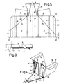
- FIG. 5 shows a cut half up to the line of symmetry 23 of the cut.
- fold lines 24 and 25 extending diagonally in the side walls 3 around the edge strips 16, 17, starting from the baking mold corners E, can be seen here, which in the outer edge strips 17 at different intervals m , n end to the line of symmetry 23, which is also a fold line.
- the folding lines 23 to 25 - in contrast to the folding lines 15, 20 to 22 - are not used to produce the baking mold 1, but rather to fold it into a package.
- the edge strips 16, 17 are returned to the plane of the side wall 3 and the wall parts of the standing baking mold 1 delimited by the diagonal folding lines 24 and 25 are bent in a direction y.
- the remaining parts of the side walls 3 with the end walls 4 fixed to them bend towards each other in the direction of the arrow z. Then both mold halves - folded around the line of symmetry 23 - can be placed one on top of the other.
- This flat package is then folded back in reverse before use, creating a ready-to-use baking pan 1.
- the edge strips 16, 17 are folded out of the plane of the side wall 3 by at least 90 ° or 180 °.
- an incision R separating them is provided in the aluminum foil in addition to the edge or crease line 15 at the upper end of the side wall 3.
Abstract
Description
Die Erfindung betrifft eine faltbare Backform mit einem Boden sowie davon ausgehenden Seiten-und Stirnwandungen, welche aus einer Werkstoffbahn mit einer zu dem von der Backforminnenfläche umgebenen Forminnenraum weisenden Kontaktschicht für das Backgut, insbesondere aus einem Karton mit einer Beschichtung aus Aluminiumfolie, zugeschnitten und dieser Zuschnitt seinerseits an vorgegebenen Linien gefaltet ist, wobei die Stirnwandungen miteinander verbundene Klappstreifen der Seitenwandungen sowie ein diesen zugeordnetes, als Knickzunge ausgebildetes Klappteil des gegen ihn durch eine Klapplinie abgegrenzten Bodens aufweisen.The invention relates to a foldable baking mold with a base and side and end walls extending therefrom, which are cut from a material web with a contact layer for the baked goods facing the interior of the mold surrounded by the baking mold surface, in particular from a cardboard box with a coating of aluminum foil, and this cutting is in turn folded on predetermined lines, the end walls having hinged strips of the side walls connected to one another and an associated folding part of the bottom, which is formed as a bent tongue and is delimited against it by a folding line.
Backformen dieser Art sind handelsüblich und werden etwa - zu einem flachen Versandstück gefaltet - Verkaufspackungen für fertige Backmischungen beigefügt, um der Hausfrau das Backen zu erleichtern. Die Backform wird hierzu auseinandergeklappt, mit dem gegebenenfalls noch zu mischenden Backgut gefüllt und in den Ofen geschoben. Um dann den fertigen Kuchen aus der Backform entfernen zu können, müssen die Wandungen wenigstens teilweise gelockert werden. Dies hat man beispielsweise nach DE-U-7 604 504 durch Verwendung eines Klebers zwischen ihren Klappstreifen und einer um deren Oberkante gebogenen Lasche versucht, welcher sich durch die Hitze des Backvorganges lösen soll. Erfahrungsgemäss löst sich der Kleber zu früh - die Backform fällt im Ofen auseinander - oder gar nicht, was das Öffnen der Backform stark erschwert. Ausserdem ist die Herstellung solcher Backformen verhältnismässig kompliziert.Baking tins of this type are commercially available and are, for example, - folded into a flat package - sales packages for ready-made baking mixes added to make baking easier for the housewife. For this purpose, the baking mold is unfolded, filled with the baked goods to be mixed if necessary, and pushed into the oven. In order to be able to remove the finished cake from the baking pan, the walls must be loosened at least partially. This has been attempted, for example, according to DE-U-7 604 504, by using an adhesive between its folding strips and a tab bent around its upper edge, which should be released by the heat of the baking process. Experience has shown that the adhesive dissolves too early - the baking pan falls apart in the oven - or not at all, which makes opening the baking pan very difficult. In addition, the manufacture of such baking molds is relatively complicated.
Die Klappstreifen nach der Entgegenhaltung bilden die Innenfläche der Backform; sie sind aussen lose angeklappt und werden durch eine sogenannte Überwurflasche an die Aussenfläche des Klappteils angedrückt. Die Innenseite der Überwurflasche ist mit einer sich auflösenden Dispersionskleberschicht an die Aussenseite der Klappstreifen angefügt. Eine über die Faltlinie aufragende Lasche besteht aus Vorsprüngen, die dank ihres Eingriffes in Einstanzung als Befestigungsorgane dienen.The folding strips after the citation form the inner surface of the baking pan; they are loosely folded on the outside and are pressed against the outer surface of the folding part by a so-called swaging bottle. The inside of the flap bottle is attached to the outside of the folding strips with a dissolving dispersion adhesive layer. A flap protruding over the fold line consists of projections which, thanks to their engagement in stamping, serve as fastening elements.
Als weiterer Mangel ist anzusehen, dass an den Seitenwänden dieser Backform vorhandene und entlang einer Perforation knickbare Randstreifen, welche in gebrauchsfertiger Lage von den Seitenwänden abgebogen sind und deren Stabilität erhöhen sollen, durch die Hitzeeinwirkung aus der abgebogenen Lage in die Ebene der Seitenwand zurückwanden und so deren Ausbauchung erlauben.Another deficiency is to be seen that on the side walls of this baking pan existing edge strips that can be bent along a perforation, which are bent from the side walls in the ready-to-use position and are intended to increase their stability, return to the plane of the side wall due to the action of heat and so on allow their bulging.
Nach der US-A-3 580 484 sind ausserdem Verpackungsbehälter mit von anderen Verpackungsteilen zu trennendem Wandungsteil mit etwa keilförmiger Trennzunge bekannt, welche beidseits mit den verbleibenden Verpackungsteilen durch Bereiche einer Gegenritzung verbunden ist.According to US-A-3 580 484, packaging containers are also known with a wall part to be separated from other packaging parts with an approximately wedge-shaped separating tongue, which is connected on both sides to the remaining packaging parts by areas of counter-scratching.
Angesichts dieser Gegebenheiten hat sich der Erfinder das Ziel gesetzt, eine Backform der eingangs erwähnten Art zu schaffen, welche während des Backvorgangs ihre Form sicher beibehält und an dessen Ende leicht vom Backgut zu lösen ist. Darüber hinaus soll diese Form auf einfache und damit besonders kostengünstige Weise hergestellt werden können.In view of these circumstances, the inventor has set itself the goal of creating a baking pan of the type mentioned at the outset, which securely maintains its shape during the baking process and at the end of which can be easily detached from the baked goods. In addition, this shape should be able to be produced in a simple and therefore particularly cost-effective manner.
Zur Lösung dieser Aufgabe führt, dass das Klappteil ausserhalb des Backforminnenraumes an die Aussenseite der Klappstreifen, die Teile der Backforminnenfläche bilden, herangeklappt ist und dass die Knickzunge aus einer Mittelzunge mit Zuglasche und beidseits der Mittelzunge vorhandenen sowie von dieser an einer Reisslinie trennbaren Flügeln besteht, welch letztere mit den Klappstreifen fest verbunden sind.To achieve this object, the folding part outside the interior of the baking mold is folded up to the outside of the folding strips, which form parts of the inside of the baking mold, and that the folding tongue consists of a central tongue with a pull tab and wings on both sides that are separable from this on a tear line, which the latter are firmly connected to the folding strips.
Nach einem weiteren Merkmal der Erfindung sollen die Reisslinien an jeder Flügelkante eine Gegenritzung bilden und so jener Mittelzunge dargestellt von den Flügeln durch die Gegenritzungen trennbar sein, dass an beiden zu trennenden Teilen jeweils ein dem Abstand der Ritzungen entsprechender Streifen verbleibt.According to a further feature of the invention, the tear lines are to form a counter-scoring on each wing edge and so that central tongue, as shown, can be separated from the wings by the counter-scoring that a strip corresponding to the spacing of the scoring remains on both parts to be separated.
Dank dieser Massgaben bleibt die Stirnwandung der Backform während des gesamten Backvorganges geschlossen; das Öffnen der Stirnwandung erfolgt ausschliesslich durch die gewollte Trennung von Mittelstück und Flügeln im Bereich der sogenannten Gegenritzungen. Die Flügel sind - bevorzugt durch einen Kleber grossflächig - mit den Klappstreifen der Seitenwandungen fest verbunden - und dies unabhängig von den herrschenden Temperaturen. Selbstverständlich sind auch andere Verbindungsmöglichkeiten hier anwendbar, was bei der zuvor beschriebenen und handelsüblichen Backform gar nicht denkbar wäre.Thanks to these measures, the end wall of the baking mold remains closed during the entire baking process; The front wall is opened exclusively by deliberately separating the center piece and wings in the area of the so-called counter-scratches. The wings are firmly connected to the folding strips of the side walls, preferably with a large area of adhesive, regardless of the prevailing temperatures. Of course, other connection options can also be used here, which would not be conceivable with the previously described and commercially available baking mold.
Da sich bei den Versuchen mit der erfindungsgemässen Backform gezeigt hat, dass das Öffnungssystem für eine ganze Behälterwandung mittels einer Zuglasche und beidseits davon verlaufenden und miteinander einen Neigungswinkel einschliessenden - also ein keilförmiges Feld begrenzenden - Bereichen einer sog. Gegenritzung ganz allgemein sehr vorteilhaft ist, wird hierfür ein gesonderter Schutz begehrt. Jeder Bereich einer Gegenritzung wird von zwei in Abstand etwa parallel verlaufenden Ritzlinien erzeugt, von denen jede mit geringer Eindringtiefe in eine andere Oberfläche der Klappzunge oder Wandung eingebracht ist.Since it has been shown in the tests with the baking mold according to the invention that the opening system for a whole container wall by means of a pull tab and areas on both sides and including an inclination angle - that is, delimiting a wedge-shaped field - of a so-called counter-scratching is generally very advantageous separate protection is required for this. Each area of a counter-scoring is produced by two scoring lines running approximately parallel at a distance, each of which is introduced into a different surface of the folding tongue or wall with a small penetration depth.
Als besonders günstig hat es sich erwiesen, dass jeder Flügel eine vom Boden der Backform ausgehende und etwa parallel zu ihnen Ritzungen verlaufende Aussenkante aufweist, welche an einer Einschnürstelle in eine obere, zur Seite weisende Aussenkante übergeht, die etwa an der Oberkante der benachbarten Seitenwandung endet. Dies erlaubt eine möglichst grossflächige Verbindung der beiden die Stirnwandung erzeugenden und aufeinander liegenden Werkstoffbahnstücke. Diese sind jedoch dank der erfindungsgemässen Ausführung leicht so weit voneinander zu trennen, dass die Backformwandungen auseinandergeklappt zu werden vermögen.It has proven to be particularly favorable that each wing has an outer edge that starts from the bottom of the baking mold and runs approximately parallel to it, which at a constriction merges into an upper, side-facing outer edge that ends approximately at the upper edge of the adjacent side wall . This allows the largest possible connection of the two material web pieces which produce the end wall and lie on one another. However, thanks to the design according to the invention, these can be easily separated from one another to such an extent that the baking mold walls can be opened out.
Um bei Seitenwandungen mit umklappbaren Randstreifen deren Zurückwandern unter Einfluss der Backhitze hintanzuhalten, ist in besonders vorteilhafter Weise in den Seitenwandungen eine etwa parallel zum Boden verlaufende Ritzung nahe oder an der Oberkante der Seitenwandung vorgesehen, welche die Kontaktschicht, also vor allem eine Aluminiumfolie durchtrennt.In order for side walls with foldable edge strips to migrate back under the influence To keep the baking heat out, a particularly advantageous manner in the side walls is an approximately parallel scratch to the floor near or on the upper edge of the side wall, which cuts through the contact layer, that is, above all, an aluminum foil.
Weitere Vorteile, Merkmale und Einzelheiten der Erfindung ergeben sich aus der nachfolgenden Beschreibung eines bevorzugten Ausführungsbeispieles sowie anhand der Zeichnung; diese zeigt in:
- Fig. 1 eine Schrägsicht auf eine Backform;
- Fig. 2 den Schnitt durch Fig. 1 nach deren Linie 11-11;
- Fig. 3 einen Detailschnitt durch die Backform etwa entsprechend der Linie 111-111 in Fig. 2;
- Fig. 4 eine Schrägsicht auf einen Teil der Backform in verändertem Zustand;
- Fig. 5 die Draufsicht auf eine Hälfte des Zuschnittes zur Herstellung einer Backform.
- Figure 1 is an oblique view of a baking pan.
- Fig. 2 shows the section through Figure 1 along the line 11-11.
- FIG. 3 shows a detail section through the baking mold approximately along the line 111-111 in FIG. 2;
- Figure 4 is an oblique view of part of the baking pan in a modified state.
- Fig. 5 is a plan view of one half of the blank for producing a baking pan.
Eine Backform 1 gemäss dem in Fig. 1 dargestellten Ausführungsbeispiel besteht aus einem Boden 2 der Länge a von beispielsweise 250 mm sowie der Breite b von 70 mm, zwei zueinander in einem Winkel w geneigt verlaufenden Seitenwänden 3 der Höhe h von etwa 75 mm sowie zwei Stirnwänden 4. Durch die Mittellinien M, N der Backform 1 ist die Symmetrieebene für die Formgebung bestimmt.A
Jede Stirnwand 4 wird von zwei Klappstreifen 5, von denen jeder mit einer Seitenwand 3 entlang einer Knicklinie 20 verbunden ist, und einer Klappzunge 6 gebildet, die entlang einer Knicklinie 21 am Boden 2 hängt. Diese Klappzunge 6 überragt mit einem Mass i die Oberkante 7 der Stirnwand 4 als Grifflasche 8. Diese Klappzunge 6 ist aus einem sich nach oben zur Grifflasche 8 hin verjüngenden Mittelstück 9 und zwei beidseits anschliessenden Flügeln 10 zusammengesetzt. Jeder Flügel 10 weist in etwa halber Höhe k (Fig. 2) eine Einschnürung 11 auf, bis zu der-vom Boden 2 her gesehen - seine Aussenkante 12 etwa parallel zu der jenes Mittelstück 9 begrenzenden äusseren Soll-Reisslinie 14 verläuft und von der ab das obere Kantenteil 13 nach aussen zur oberen Backformseitenkante 15 gerichtet ist. Entlang dieser sind jeweils zwei schmale Randstreifen 16, 17 zu erkennen. Die Knicklinie zwischen diesen beiden ist mit 22 bezeichnet.Each end wall 4 is formed by two
Alle beschriebenen Teile sind gemeinsam aus einem Materialstreifen zugeschnitten, der aus einer Kartonschicht 29 mit aufkaschierter Aluminiumfolie 30 besteht. Letztere bildet die zum Forminnenraum Q gerichtete Kontaktschicht, welche an das nicht wiedergegebene Backgut grenzt.All the parts described are cut together from a strip of material consisting of a
Wie die Fig. 2, 3, 4 erkennen lassen, ist die beschriebene äussere Soll-Reisslinie 14 zwischen dem Mittelstück 9 und dem Flügel 10 der Klappzunge 6 in die Kartonschicht 29 eingeprägt, verletzt also die Aluminiumfolie 30 nicht. Eine in diese eingebrachte innere Soll-Reisslinie 18 verläuft als Gegenritzung parallel dazu in einem Abstand e.As can be seen in FIGS. 2, 3, 4, the described outer desired
Wird nun an der Grifflasche 8 des Mittelstückes 9 in Pfeilrichtung x gezogen, kann letzteres gemäss Fig. 4 von den - insgesamt mit den Klappstreifen 5verklebten (Feld F) - Flügeln 10 so getrennt werden, dass an diesen ein Streifen 19 aus Aluminiumfolie 10 und einer dünnen Schicht des Kartons 29 verbleibt. Die beiden Streifen 19 verlaufen über die gesamte Höhe der Stirnwand 4.If the
Fig. 5 zeigt eine Zuschnitthälfte bis zur Symmetrielinie 23 des Zuschnittes. Ausser den bereits beschriebenen Knicklinien 15, 20, 21, 22 sind hier noch - von den Backformecken E ausgehende - diagonal in den Seitenwänden 3 um den Randstreifen 16, 17 verlaufende Faltlinien 24 und 25 zu erkennen, die im äusseren Randstreifen 17 in unterschiedlichen Abständen m, n zur Symmetrielinie 23 enden, die ebenfalls eine Faltlinie ist.5 shows a cut half up to the line of
Die Faltlinien 23 bis 25 dienen - im Unterschied zu den Knicklinien 15, 20 bis 22-nicht zur Herstellung der Backform 1, sondern zu deren Faltung zu einem Versandstück. Hierzu werden die Randstreifen 16, 17 in die Ebene der Seitenwand 3 zurückgeführt und die von den diagonalen Faltlinien 24 bzw. 25 begrenzten Wandungsteile der stehenden Backform 1 in eine Richtung y gebogen. Die übrigen Teile der Seitenwände 3 mit den an ihnen festliegenden Stirnwänden 4 knicken dabei in Pfeilrichtung z aufeinander zu. Anschliessend können beide Formhälften - um die Symmetrielinie 23 gefaltet - aufeinandergelegt werden.The
Dieses flache Versandstück wird dann vor seiner Verwendung in umgekehrter Weise zurückgeklappt, wodurch eine gebrauchsfertige Backform 1 entsteht. Zur Verbesserung der Wandstabilität werden die Randstreifen 16, 17 um zumindest 90° bzw. 180° aus der Ebene der Seitenwand 3 geklappt.This flat package is then folded back in reverse before use, creating a ready-to-use
Um eine Rückformung der Randstreifen 16, 17 unter Einfluss der Backtemperatur und einer dadurch verursachten Spannung in der Aluminiumfolie 30 hintanzuhalten, ist jeweils neben der Rand- oder Knicklinie 15 am oberen Ende der Seitenwand 3 in der Aluminiumfolie eine diese durchtrennende Ritzung R angebracht.In order to prevent reshaping of the
Claims (6)
Priority Applications (1)
| Application Number | Priority Date | Filing Date | Title |
|---|---|---|---|
| AT80102601T ATE10570T1 (en) | 1979-05-10 | 1980-05-10 | FOLDABLE BAKING PAN. |
Applications Claiming Priority (2)
| Application Number | Priority Date | Filing Date | Title |
|---|---|---|---|
| DE2918814 | 1979-05-10 | ||
| DE2918814A DE2918814C2 (en) | 1979-05-10 | 1979-05-10 | Foldable baking pan |
Publications (3)
| Publication Number | Publication Date |
|---|---|
| EP0019783A2 EP0019783A2 (en) | 1980-12-10 |
| EP0019783A3 EP0019783A3 (en) | 1981-05-06 |
| EP0019783B1 true EP0019783B1 (en) | 1984-12-05 |
Family
ID=6070375
Family Applications (1)
| Application Number | Title | Priority Date | Filing Date |
|---|---|---|---|
| EP80102601A Expired EP0019783B1 (en) | 1979-05-10 | 1980-05-10 | Collapsible baking form |
Country Status (4)
| Country | Link |
|---|---|
| EP (1) | EP0019783B1 (en) |
| AT (1) | ATE10570T1 (en) |
| DE (1) | DE2918814C2 (en) |
| GB (1) | GB2052952B (en) |
Families Citing this family (5)
| Publication number | Priority date | Publication date | Assignee | Title |
|---|---|---|---|---|
| DE3149645A1 (en) * | 1981-12-15 | 1983-07-21 | Meurer Nonfood Product GmbH, 7760 Radolfzell | CONTAINER |
| CH674916A5 (en) * | 1987-10-16 | 1990-08-15 | Migros | |
| AU632690B2 (en) * | 1990-07-26 | 1993-01-07 | Amcor Limited | An improved container assembly |
| FR2789284B1 (en) | 1999-02-09 | 2001-04-13 | Nordia | CARDBOARD MOLD |
| NL1020465C2 (en) | 2002-04-25 | 2003-10-28 | Snel Golfkarton B V | Baking mould made by folding cardboard blank, has side walls and end walls joined together via cooperating tabs and spaces |
Citations (1)
| Publication number | Priority date | Publication date | Assignee | Title |
|---|---|---|---|---|
| DE7604504U1 (en) * | 1976-02-16 | 1976-10-07 | E. Gundlach Kg, 4800 Bielefeld | Box-shaped baking pan |
Family Cites Families (5)
| Publication number | Priority date | Publication date | Assignee | Title |
|---|---|---|---|---|
| CH391616A (en) * | 1962-02-24 | 1965-05-15 | Alupak Ag | Collapsible container |
| US3580484A (en) * | 1969-03-24 | 1971-05-25 | Michael S Schneider | Portion access pie plate |
| DE2456209A1 (en) * | 1974-11-28 | 1976-08-12 | Geb Oehm Margot Wichmann | Container with provision for automatic opening - has adhesive action between opening part and body interrupted by hot fluid or gas added to contents |
| DE7729367U1 (en) * | 1977-09-22 | 1978-03-09 | Graphia Gundlach Gmbh Hans | Folding box for chocolates or similar products |
| CA1115674A (en) * | 1978-11-27 | 1982-01-05 | Harold D. Johnson | Ovenable paperboard carton |
-
1979
- 1979-05-10 DE DE2918814A patent/DE2918814C2/en not_active Expired
-
1980
- 1980-05-10 EP EP80102601A patent/EP0019783B1/en not_active Expired
- 1980-05-10 AT AT80102601T patent/ATE10570T1/en not_active IP Right Cessation
- 1980-05-12 GB GB8015706A patent/GB2052952B/en not_active Expired
Patent Citations (1)
| Publication number | Priority date | Publication date | Assignee | Title |
|---|---|---|---|---|
| DE7604504U1 (en) * | 1976-02-16 | 1976-10-07 | E. Gundlach Kg, 4800 Bielefeld | Box-shaped baking pan |
Also Published As
| Publication number | Publication date |
|---|---|
| EP0019783A2 (en) | 1980-12-10 |
| GB2052952B (en) | 1983-06-22 |
| DE2918814C2 (en) | 1984-04-19 |
| EP0019783A3 (en) | 1981-05-06 |
| GB2052952A (en) | 1981-02-04 |
| ATE10570T1 (en) | 1984-12-15 |
| DE2918814A1 (en) | 1980-11-20 |
Similar Documents
| Publication | Publication Date | Title |
|---|---|---|
| DE2414291C2 (en) | Portable packing box | |
| CH648801A5 (en) | SHELL, AND CUTTING OUT OF CARDBOARD, AND METHOD FOR THE PRODUCTION THEREOF. | |
| CH643507A5 (en) | PACKAGE WITH A GROUP OF ITEMS, METHOD AND CUT FOR PRODUCTION THEREOF. | |
| CH417466A (en) | packaging | |
| CH629437A5 (en) | Carton, method for its manufacture, and blank for carrying out the method | |
| EP0019783B1 (en) | Collapsible baking form | |
| EP0039939B1 (en) | Tray-type container | |
| DE2404936B2 (en) | PACKAGING FOR BEVERAGE BOTTLES | |
| CH657105A5 (en) | PLASTIC-COVERED CARDBOARD CUTTING AND CONTAINER MADE THEREOF. | |
| DE2947716A1 (en) | OVEN-RESISTANT CARDBOARD BOARD FOR USE IN A MICROWAVE OVEN AND IN CONVENTIONAL OVENS | |
| DE2243346A1 (en) | DISPENSING CASE, -NAUTE, -OPENING OR THE LIKE A CARDBOARD, CARDBOARD, OR THE LIKE. -BOX | |
| DE602006000546T2 (en) | Made of semi-rigid material, lined inside with a thermoformed sheet of thermoplastic material shell | |
| CH537321A (en) | Packaging, especially for biscuits | |
| DE202007009313U1 (en) | Cardboard package for use in aircraft, has side wall limited by straight lines that form flaps between sections by punch-through lines, where flaps lie in broadening of one strip on base in erected condition of even section | |
| EP0082104B1 (en) | Container | |
| DE1486295A1 (en) | carton | |
| DE3025373A1 (en) | Cardboard blank assembled cake tin - has extra fold line at ends for easier removal of cake from tin | |
| DE1196595B (en) | Baking pan for cakes or other pastries in block form | |
| DE2533205A1 (en) | PACKAGING CONTAINER | |
| DE20319691U1 (en) | Blank for a container and container made from the blank | |
| DE1536204C (en) | Container made of cardboard with a gable-shaped top closure | |
| DE1486610C (en) | In one piece from floating fiber fabric by means of suction in a form made cardboard for eggs or the like | |
| DE2002995A1 (en) | Assembled, leak-proof cardboard | |
| DE202019103234U1 (en) | Blank for the production of a packaging container and packaging container | |
| DE1786234C (en) | Group packing |
Legal Events
| Date | Code | Title | Description |
|---|---|---|---|
| PUAI | Public reference made under article 153(3) epc to a published international application that has entered the european phase |
Free format text: ORIGINAL CODE: 0009012 |
|
| AK | Designated contracting states |
Designated state(s): AT BE CH FR IT LI NL SE |
|
| PUAL | Search report despatched |
Free format text: ORIGINAL CODE: 0009013 |
|
| AK | Designated contracting states |
Designated state(s): AT BE CH FR IT LI NL SE |
|
| 17P | Request for examination filed |
Effective date: 19810521 |
|
| RAP1 | Party data changed (applicant data changed or rights of an application transferred) |
Owner name: MEURER NONFOOD PRODUCT GMBH |
|
| ITF | It: translation for a ep patent filed |
Owner name: BUGNION S.P.A. |
|
| GRAA | (expected) grant |
Free format text: ORIGINAL CODE: 0009210 |
|
| AK | Designated contracting states |
Designated state(s): AT BE CH FR IT LI NL SE |
|
| REF | Corresponds to: |
Ref document number: 10570 Country of ref document: AT Date of ref document: 19841215 Kind code of ref document: T |
|
| ET | Fr: translation filed | ||
| PLBE | No opposition filed within time limit |
Free format text: ORIGINAL CODE: 0009261 |
|
| STAA | Information on the status of an ep patent application or granted ep patent |
Free format text: STATUS: NO OPPOSITION FILED WITHIN TIME LIMIT |
|
| 26N | No opposition filed | ||
| PGFP | Annual fee paid to national office [announced via postgrant information from national office to epo] |
Ref country code: AT Payment date: 19890510 Year of fee payment: 10 |
|
| PGFP | Annual fee paid to national office [announced via postgrant information from national office to epo] |
Ref country code: FR Payment date: 19890512 Year of fee payment: 10 |
|
| PGFP | Annual fee paid to national office [announced via postgrant information from national office to epo] |
Ref country code: BE Payment date: 19890518 Year of fee payment: 10 |
|
| PGFP | Annual fee paid to national office [announced via postgrant information from national office to epo] |
Ref country code: SE Payment date: 19890523 Year of fee payment: 10 |
|
| ITTA | It: last paid annual fee | ||
| PGFP | Annual fee paid to national office [announced via postgrant information from national office to epo] |
Ref country code: NL Payment date: 19890531 Year of fee payment: 10 |
|
| PGFP | Annual fee paid to national office [announced via postgrant information from national office to epo] |
Ref country code: CH Payment date: 19890718 Year of fee payment: 10 |
|
| PG25 | Lapsed in a contracting state [announced via postgrant information from national office to epo] |
Ref country code: AT Effective date: 19900510 |
|
| PG25 | Lapsed in a contracting state [announced via postgrant information from national office to epo] |
Ref country code: SE Effective date: 19900511 |
|
| PG25 | Lapsed in a contracting state [announced via postgrant information from national office to epo] |
Ref country code: LI Effective date: 19900531 Ref country code: CH Effective date: 19900531 Ref country code: BE Effective date: 19900531 |
|
| BERE | Be: lapsed |
Owner name: MEURER MONFOOD PRODUCT G.M.B.H. Effective date: 19900531 |
|
| PG25 | Lapsed in a contracting state [announced via postgrant information from national office to epo] |
Ref country code: NL Effective date: 19901201 |
|
| NLV4 | Nl: lapsed or anulled due to non-payment of the annual fee | ||
| PG25 | Lapsed in a contracting state [announced via postgrant information from national office to epo] |
Ref country code: FR Effective date: 19910131 |
|
| REG | Reference to a national code |
Ref country code: CH Ref legal event code: PL |
|
| REG | Reference to a national code |
Ref country code: FR Ref legal event code: ST |
|
| EUG | Se: european patent has lapsed |
Ref document number: 80102601.4 Effective date: 19910114 |