EP0019082B1 - Procédé et appareil pour la focalisation d'ondes élastiques - Google Patents
Procédé et appareil pour la focalisation d'ondes élastiques Download PDFInfo
- Publication number
- EP0019082B1 EP0019082B1 EP80101913A EP80101913A EP0019082B1 EP 0019082 B1 EP0019082 B1 EP 0019082B1 EP 80101913 A EP80101913 A EP 80101913A EP 80101913 A EP80101913 A EP 80101913A EP 0019082 B1 EP0019082 B1 EP 0019082B1
- Authority
- EP
- European Patent Office
- Prior art keywords
- acoustic waves
- lens
- waves
- medium
- focusing
- Prior art date
- Legal status (The legal status is an assumption and is not a legal conclusion. Google has not performed a legal analysis and makes no representation as to the accuracy of the status listed.)
- Expired
Links
- 238000000034 method Methods 0.000 title claims description 5
- 229910052751 metal Inorganic materials 0.000 claims description 34
- 239000002184 metal Substances 0.000 claims description 34
- 239000007788 liquid Substances 0.000 claims description 26
- 230000005855 radiation Effects 0.000 claims description 9
- 239000010409 thin film Substances 0.000 claims 1
- OKKJLVBELUTLKV-UHFFFAOYSA-N Methanol Chemical compound OC OKKJLVBELUTLKV-UHFFFAOYSA-N 0.000 description 9
- CSCPPACGZOOCGX-UHFFFAOYSA-N Acetone Chemical compound CC(C)=O CSCPPACGZOOCGX-UHFFFAOYSA-N 0.000 description 6
- LFQSCWFLJHTTHZ-UHFFFAOYSA-N Ethanol Chemical compound CCO LFQSCWFLJHTTHZ-UHFFFAOYSA-N 0.000 description 6
- 239000000463 material Substances 0.000 description 4
- 238000009659 non-destructive testing Methods 0.000 description 4
- 238000006243 chemical reaction Methods 0.000 description 3
- 239000011343 solid material Substances 0.000 description 3
- XLYOFNOQVPJJNP-UHFFFAOYSA-N water Substances O XLYOFNOQVPJJNP-UHFFFAOYSA-N 0.000 description 3
- 238000003745 diagnosis Methods 0.000 description 2
- 238000001704 evaporation Methods 0.000 description 2
- 239000012530 fluid Substances 0.000 description 2
- 239000007789 gas Substances 0.000 description 2
- 239000011521 glass Substances 0.000 description 2
- 239000011810 insulating material Substances 0.000 description 2
- BASFCYQUMIYNBI-UHFFFAOYSA-N platinum Chemical compound [Pt] BASFCYQUMIYNBI-UHFFFAOYSA-N 0.000 description 2
- 239000012780 transparent material Substances 0.000 description 2
- 229920002799 BoPET Polymers 0.000 description 1
- OKTJSMMVPCPJKN-UHFFFAOYSA-N Carbon Chemical compound [C] OKTJSMMVPCPJKN-UHFFFAOYSA-N 0.000 description 1
- ZOKXTWBITQBERF-UHFFFAOYSA-N Molybdenum Chemical compound [Mo] ZOKXTWBITQBERF-UHFFFAOYSA-N 0.000 description 1
- 239000005041 Mylar™ Substances 0.000 description 1
- 238000010521 absorption reaction Methods 0.000 description 1
- 229910052799 carbon Inorganic materials 0.000 description 1
- 230000008878 coupling Effects 0.000 description 1
- 238000010168 coupling process Methods 0.000 description 1
- 238000005859 coupling reaction Methods 0.000 description 1
- 238000010894 electron beam technology Methods 0.000 description 1
- 238000004519 manufacturing process Methods 0.000 description 1
- 150000002739 metals Chemical class 0.000 description 1
- 229910052750 molybdenum Inorganic materials 0.000 description 1
- 239000011733 molybdenum Substances 0.000 description 1
- 230000003287 optical effect Effects 0.000 description 1
- 229910052697 platinum Inorganic materials 0.000 description 1
- 239000010453 quartz Substances 0.000 description 1
- 239000003870 refractory metal Substances 0.000 description 1
- VYPSYNLAJGMNEJ-UHFFFAOYSA-N silicon dioxide Inorganic materials O=[Si]=O VYPSYNLAJGMNEJ-UHFFFAOYSA-N 0.000 description 1
- 239000007787 solid Substances 0.000 description 1
- WFKWXMTUELFFGS-UHFFFAOYSA-N tungsten Chemical compound [W] WFKWXMTUELFFGS-UHFFFAOYSA-N 0.000 description 1
- 229910052721 tungsten Inorganic materials 0.000 description 1
- 239000010937 tungsten Substances 0.000 description 1
- 229910052720 vanadium Inorganic materials 0.000 description 1
- LEONUFNNVUYDNQ-UHFFFAOYSA-N vanadium atom Chemical compound [V] LEONUFNNVUYDNQ-UHFFFAOYSA-N 0.000 description 1
Images

Classifications
-
- G—PHYSICS
- G10—MUSICAL INSTRUMENTS; ACOUSTICS
- G10K—SOUND-PRODUCING DEVICES; METHODS OR DEVICES FOR PROTECTING AGAINST, OR FOR DAMPING, NOISE OR OTHER ACOUSTIC WAVES IN GENERAL; ACOUSTICS NOT OTHERWISE PROVIDED FOR
- G10K15/00—Acoustics not otherwise provided for
- G10K15/04—Sound-producing devices
- G10K15/046—Sound-producing devices using optical excitation, e.g. laser bundle
-
- G—PHYSICS
- G10—MUSICAL INSTRUMENTS; ACOUSTICS
- G10K—SOUND-PRODUCING DEVICES; METHODS OR DEVICES FOR PROTECTING AGAINST, OR FOR DAMPING, NOISE OR OTHER ACOUSTIC WAVES IN GENERAL; ACOUSTICS NOT OTHERWISE PROVIDED FOR
- G10K11/00—Methods or devices for transmitting, conducting or directing sound in general; Methods or devices for protecting against, or for damping, noise or other acoustic waves in general
- G10K11/18—Methods or devices for transmitting, conducting or directing sound
- G10K11/26—Sound-focusing or directing, e.g. scanning
- G10K11/32—Sound-focusing or directing, e.g. scanning characterised by the shape of the source
-
- G—PHYSICS
- G01—MEASURING; TESTING
- G01N—INVESTIGATING OR ANALYSING MATERIALS BY DETERMINING THEIR CHEMICAL OR PHYSICAL PROPERTIES
- G01N2291/00—Indexing codes associated with group G01N29/00
- G01N2291/02—Indexing codes associated with the analysed material
- G01N2291/028—Material parameters
- G01N2291/02827—Elastic parameters, strength or force
Definitions
- the invention relates to a method and an apparatus for focusing elastic waves in a medium.
- acoustic waves for non-destructive testing of articles and for medical diagnosis have previously been suggested. These acoustic waves have been produced primarily by piezoelectric transducers.
- Another means for generating acoustic waves has been to employ a laser.
- the laser can be focused to such a small point of an acoustic wave generator that the acoustic waves are a very narrow beam.
- the use of a laser has enabled the acoustic waves to be produced from a source of thermal energy and directed to a selected area for non-destructive testing of an article or for medical diagnosis, for example, without requiring an acoustic lens for focusing the acoustic waves.
- Examples of such a laser are disclosed in U.S. patent 3,322,231 to Gour- nay, U.S. patent 3,532,181 to DeMaria, and U.S. patent 3,583,212 to Nanney.
- a laser is a relatively expensive device.
- its utilization as a source of thermal energy even though no focusing of the acoustic waves is required due to the beam being focused prior to striking the acoustic wave generator, has been limited.
- the present invention is intended to overcome the drawbacks of prior art devices. It provides an apparatus for producing focused elastic waves comprising a radiation source transferring radiation pulses to an element which absorbs the radiation and produces thermal energy, said element being in contact with a liquid medium, characterized in that said element constitutes a focusing element having a curved surface and is associated with adjusting means for adjusting the curvature of said surface, whereby the thermal energy produced in the focusing element generates acoustic waves in the liquid medium to be focused upon an object.
- the invention also discloses a method of using such an apparatus.
- the advantages offered by the invention are mainly that expensive laser energy sources and complicated piezoelectric transducer elements can be replaced by more simpler energy sources and more convenient transducer means and that it provides adjustable focusing.
- the present invention is capable of using inexpensive sources of pulsed thermal energy such as a flash lamp, for example, to produce elastic waves through converting the thermal energy from the flash lamp to the elastic waves while simultaneously focusing the waves.
- the present invention enables a relatively low cost source of thermal energy to be employed for producing acoustic waves, which can be used for non-destructive testing, for example.
- the acoustic waves When utilized for non-destructive testing, for example, it is necessary for the acoustic waves to have a relatively large amplitude in order that the signals tested can be detected.
- the present invention meets this requirement through focusing the acoustic waves while efficiently converting the thermal energy to acoustic waves simultaneously.
- a tank 10 having a liquid 11 such as water, for example, therein.
- a wall 12 of the tank 10 has a piano concave lens 14, which is formed of a high thermal insulating material such as glass or quartz, for example, mounted on its inner surface.
- the concave side of the lens 14 has a film 15 of opaque metal bonded thereto by suitable means such as evaporating the film 15 of metal thereon.
- the metal of the film 15 can be any suitable material for converting thermal energy in the form of light into elastic energy in the form of acoustic waves.
- the metal of the film 15 is preferably a refractory metal such as molybdenum, tungsten, platinum or vanadium, for example.
- the film 15 of metal is clamped between the lens 14, which is a body of solid material, and the liquid 11. This increases the conversion efficiency of the film 15 of metal.
- the thickness of the film 15 of metal is selected so that it absorbs as much of the light energy as possible while being as thin as possible to cause most of the heat from the light to be applied to the liquid 11 which more efficiently converts the thermal energy into elastic energy due to its higher thermal expansion coefficient.
- the thickness of the metal film 15 should be at least the reciprocal of the optical absorption constant of the metal of the film 15.
- the thickness of the metal of the film 15 is within the range of 300 Angstroms to 500 Angstroms.
- the curvature of the film 15 of metal is the same as the curvature of the concave side of the lens 14 to which the film 15 is bonded. This curvature is selected so that acoustic waves 19, which are generated in the liquid 11 as a result of the thermal energy produced by the light from the flash lamp 16 striking the metal film 15, are focused to strike an object 20 which is to be non-destructively tested.
- the object 20 is supported within the liquid 11 in the tank 10 by any suitable means (not shown). While the object 20 is disclosed as being within the liquid 11, it should be understood that it could be exterior of the liquid 11, but this would result in the focus of the acoustic waves 19 on the object 20 not being as sharp. This also requires there to be some acoustic coupling between the tank 10 and the ambient surrounding the object 20.
- the curvature of the metal film 15 focuses the acoustic wave 19 to converge the energy on the object 20. Thus, this produces a higher density of energy at the object 20.
- a transducer 22 is disposed within the liquid 11 to detect the acoustic waves 19 after having struck the object 20.
- the waves detected by the transducer 22 are compared with reference signals, which have previously been determined. This comparison determines whether the object 20 is satisfactory or not.
- the reference signals are developed through use of a relatively flawless piece of the material to be tested, for example.
- the relatively flawless piece is disposed within the liquid 11 at the location of the object 20, and the reference signals are produced therefrom by obtaining a set of curves, for example, through analyzing the frequencies of the signals received at the transducer 22.
- the transducer 22 has been shown as having the acoustic waves 19 pass through the object 20 and then be detected by the transducer 22, it should be understood that such is not necessary. That is, the transducer 22 could receive reflected waves from the object 20 rather than having the waves pass through the object 20. This would require the transducer 22 to be disposed forward of the object 20 but to its side so as to not be in the path of the waves 19 focused from the curved film 15 of metal.
- Fig. 1 has shown and described the source of thermal energy as being the pulsed flash lamp 16, it should be understood that any source of pulsed thermal energy could be utilized.
- a laser, a pulsed carbon arc, an electron beam, an X-ray, or an atomic beam, for example, could be employed as the source of pulsed thermal energy.
- all of these are more expensive than the flash lamp 16, and the present invention enables a weak and relatively inexpensive source of pulsed thermal energy to be utilized.
- Fig. 1 While the apparatus of Fig. 1 has shown and described the film 15 of metal as being disposed within the liquid 11, it should be understood that it could be disposed within any fluid. However, gases such as air, for example, do not have a high thermal expansion coefficient as do liquids such as water, acetone, ethanol, or methanol, for example. Thus, the amplitude of the acoustic waves 19 would be much smaller and more difficult to detect.
- the film 15 of metal also could be mounted within a body of solid material.
- the body would have to be cut in some manner as the focal plane of the acoustic waves 19 at which the object 20 is to be located so that the object 20 could be inserted within the body.
- Fig. 1 While the apparatus of Fig. 1 has shown the flash lamp 16 as being directed to the curved film 15 of metal through the lens 14, it should be understood that various types of lens arrangements could be employed between the flash lamp 16 and the lens 14 to maximize the application of the light energy from the flash lamp 16 to the lens 14. This light maximizing arrangement would be disposed exterior of the tank 10.
- flash lamp 16 has been shown and described as being exterior of the tank 10, it should be understood that the flash lamp 16 could be within the liquid 11. This would be particularly true where the medium is not the liquid 11 but is a gas or a solid.
- the radius of curvature of the concave side of the lens 14 is selected to provide the focusing at the desired distance from the film 15 of metal. This is determined by the elastic velocity of the material of the lens 14 and the liquid 11.
- the film 15 of metal needs to be clamped between the lens 14 and the liquid 11 at their interface as shown in U.S. patent 4,137,991 to Melcher et al, for example.
- the apparatus of fig. 1 will produce elastic waves in the liquid 11 even if the film 15 of metal is not clamped but the amplitude of the waves will be much smaller and hence the wave more difficult to detect.
- a tank 30 having a liquid 31 such as water, for example, therein.
- a liquid 31 such as water, for example, therein.
- suitable liquids such as acetone, methanol, and ethanol, for example, may be employed if desired.
- the tank 30 is preferably formed of glass. However, the tank 30 may be formed of any other suitable transparent material.
- the tank 30 has a lens 32, which is an arcuate portion of a cylinder, disposed therein.
- the lens 32 is formed of a strip of Mylar (registered Trade Mark), which is a high thermal insulating material, having a thickness of five to ten mils.
- the lens 32 has a film 33 of opaque metal bonded thereto by suitable means such as evaporating the film 33 of metal thereon.
- the metal of the film 33 may be of any of the same metals as the metal of the film 15.
- the lens 32 has one edge supported within a groove 34 in a clamp 35 and its other end supported in a groove 36 in a clamp 37.
- Clamping screws 38 extend through the clamps 35 and 37 with each of the screws 38 having a nut 39 cooperating therewith. Accordingly, by tightening the clamping screws 38, the clamp 35 is moved closer to the clamp 37 to increase the curvature of the lens 32 and change the effective focal length.
- the flash lamp 16 has light reflected therefrom by the reflector 16' and through a wall 40 of the tank 30 to the lens 32.
- the thickness of the film 33 of metal is selected in the same manner as the thickness of the metal of the film 15 is selected.
- the lens 32 and the film 33 of metal have a radius of curvature selected through controlling the distance between the clamps 35 and 37 so that acoustic waves 41, which are generated in the liquid 31 as a result of thermal energy produced by the light from the flash lamp 16 striking the metal film 33, are focused to strike the object 20 which is to be non-destructively tested.
- the waves 41 are focused to a line, which is the axis of the cylinder of which the lens 32 is an arcuate portion.
- the apparatus of fig. 2 utilizes a relatively inexpensive lens in comparison to that of the apparatus of fig. 1.
- the use of the movable clamp 35 through the clamping screws 38 enables easy change of the effective focal length of the lens 32.
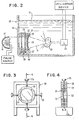
- the frame 50 for disposition within the tank 30 of fig. 2.
- the frame 50 has a lens 51, which is formed of the same material as the lens 32.
- the lens 51 has a film 52 of metal bonded thereto in the same manner as the film 33 of metal is bonded to the lens 32.
- the circumferential edge of the lens 51 is disposed within an arcuate groove 53 in each of a plurality of arcuate edge clamps 54.
- a screw 55 exerts pressure on each of the edge clamps 54.
- the lens 51 has its radius of curvature easily increased to change the effective focal length.
- the lens 51 functions in the same manner as the lens 14 or the lens 32.
- the apparatus of figs. 3 and 4 has the same low cost fabrication advantage as does the lens 32 of fig. 2. Additionally, it also has the advantage of having the effective focal length easily changed through changing the pressure on the circumference of the edge clamps 54.
- the apparatus of fig. 2 or the apparatus of figs. 3 and 4 could be disposed within the tank 10. Of course, this would require the disposition of the lens 32 or the lens 51 in alignment with the opening 17 in the same manner as the lens 14. Likewise, the apparatus of fig. 1 could be utilized with the transparent tank 30 of fig. 2 if desired.
- An advantage of this invention is that a relatively inexpensive source of thermal energy may be employed for producing detectable elastic waves. Another advantage of this invention is that an object may be tested without being damaged. A further advantage of this invention is that elastic waves of relatively large amplitude are generated.
Landscapes
- Physics & Mathematics (AREA)
- Engineering & Computer Science (AREA)
- Acoustics & Sound (AREA)
- Multimedia (AREA)
- Optics & Photonics (AREA)
- Investigating Or Analyzing Materials By The Use Of Ultrasonic Waves (AREA)
- Investigating Or Analyzing Materials Using Thermal Means (AREA)
- Ultra Sonic Daignosis Equipment (AREA)
- Apparatuses For Generation Of Mechanical Vibrations (AREA)
Claims (8)
Applications Claiming Priority (2)
| Application Number | Priority Date | Filing Date | Title |
|---|---|---|---|
| US06/040,340 US4269067A (en) | 1979-05-18 | 1979-05-18 | Method and apparatus for focusing elastic waves converted from thermal energy |
| US40340 | 1979-05-18 |
Publications (2)
| Publication Number | Publication Date |
|---|---|
| EP0019082A1 EP0019082A1 (fr) | 1980-11-26 |
| EP0019082B1 true EP0019082B1 (fr) | 1983-08-03 |
Family
ID=21910478
Family Applications (1)
| Application Number | Title | Priority Date | Filing Date |
|---|---|---|---|
| EP80101913A Expired EP0019082B1 (fr) | 1979-05-18 | 1980-04-10 | Procédé et appareil pour la focalisation d'ondes élastiques |
Country Status (4)
| Country | Link |
|---|---|
| US (1) | US4269067A (fr) |
| EP (1) | EP0019082B1 (fr) |
| JP (1) | JPS55155248A (fr) |
| DE (1) | DE3064477D1 (fr) |
Families Citing this family (35)
| Publication number | Priority date | Publication date | Assignee | Title |
|---|---|---|---|---|
| US4512197A (en) * | 1983-09-01 | 1985-04-23 | The United States Of America As Represented By The Secretary Of The Navy | Apparatus for generating a focusable and scannable ultrasonic beam for non-destructive examination |
| US4608979A (en) * | 1984-02-22 | 1986-09-02 | Washington Research Foundation | Apparatus for the noninvasive shock fragmentation of renal calculi |
| GB8612760D0 (en) * | 1986-05-27 | 1986-07-02 | Unilever Plc | Ultrasonic field generation |
| BR8807897A (pt) * | 1989-01-13 | 1991-04-02 | Fiz Tekhn I Im A F Loffe Akade | Aparelho para produzir ondas de choque focalizadas |
| GB2270159A (en) * | 1992-03-13 | 1994-03-02 | Scient Generics Ltd | Optically controlled ultrasound array |
| US8182473B2 (en) | 1999-01-08 | 2012-05-22 | Palomar Medical Technologies | Cooling system for a photocosmetic device |
| US20080294152A1 (en) * | 1996-12-02 | 2008-11-27 | Palomar Medical Technologies, Inc. | Cooling System For A Photocosmetic Device |
| US6517532B1 (en) | 1997-05-15 | 2003-02-11 | Palomar Medical Technologies, Inc. | Light energy delivery head |
| DK0991372T3 (da) | 1997-05-15 | 2004-12-06 | Palomar Medical Tech Inc | Apparat til dermatologisk behandling |
| WO1999046005A1 (fr) * | 1998-03-12 | 1999-09-16 | Palomar Medical Technologies, Inc. | Systeme d'application de rayonnement electromagnetique sur la peau |
| US6253619B1 (en) * | 1999-08-20 | 2001-07-03 | General Electric Company | Adjustable acoustic mirror |
| US20080183162A1 (en) * | 2000-12-28 | 2008-07-31 | Palomar Medical Technologies, Inc. | Methods And Devices For Fractional Ablation Of Tissue |
| US7329274B2 (en) * | 2001-11-29 | 2008-02-12 | Palomar Medical Technologies, Inc. | Conforming oral phototherapy applicator |
| US20060194164A1 (en) * | 2004-12-09 | 2006-08-31 | Palomar Medical Technologies, Inc. | Oral appliance with heat transfer mechanism |
| AU2003245573A1 (en) | 2002-06-19 | 2004-01-06 | Palomar Medical Technologies, Inc. | Method and apparatus for treatment of cutaneous and subcutaneous conditions |
| EP2522293A2 (fr) * | 2002-10-23 | 2012-11-14 | Palomar Medical Technologies, Inc. | Dispositif de phototraitement utilisable conjointement avec des substances réfrigérantes et topiques |
| EP1706793B1 (fr) | 2004-01-20 | 2010-03-03 | Carl Zeiss SMT AG | Appareil microlithographique d'insolation par projection et dispositif de mesure pour objectif de projection |
| WO2005099369A2 (fr) * | 2004-04-09 | 2005-10-27 | Palomar Medical Technologies, Inc. | Procedes et traitement pour la production de reseaux d'ilots traites par rayonnement electromagnetique dans des tissus et leurs utilisations |
| US7856985B2 (en) | 2005-04-22 | 2010-12-28 | Cynosure, Inc. | Method of treatment body tissue using a non-uniform laser beam |
| US20060272418A1 (en) * | 2005-06-03 | 2006-12-07 | Brown University | Opto-acoustic methods and apparatus for perfoming high resolution acoustic imaging and other sample probing and modification operations |
| US7624640B2 (en) * | 2005-06-03 | 2009-12-01 | Brown University | Opto-acoustic methods and apparatus for performing high resolution acoustic imaging and other sample probing and modification operations |
| WO2007035444A2 (fr) | 2005-09-15 | 2007-03-29 | Palomar Medical Technologies, Inc. | Dispositif de caractérisation optique de la peau |
| DE102006021797A1 (de) | 2006-05-09 | 2007-11-15 | Carl Zeiss Smt Ag | Optische Abbildungseinrichtung mit thermischer Dämpfung |
| US7586957B2 (en) | 2006-08-02 | 2009-09-08 | Cynosure, Inc | Picosecond laser apparatus and methods for its operation and use |
| WO2008074005A1 (fr) * | 2006-12-13 | 2008-06-19 | Palomar Medical Technologies, Inc. | Applications cosmétiques et biomédicales d'énergie ultrasonore et procédés de génération de celles-ci |
| US8302480B2 (en) * | 2007-02-05 | 2012-11-06 | Brown University | Enhanced ultra-high resolution acoustic microscope |
| WO2009108933A2 (fr) * | 2008-02-28 | 2009-09-03 | Palomar Medical Technologies, Inc. | Systèmes et procédés de traitement des tissus mous |
| US20090254076A1 (en) * | 2008-03-17 | 2009-10-08 | Palomar Medical Corporation | Method and apparatus for fractional deformation and treatment of tissue |
| WO2010115209A2 (fr) * | 2009-04-03 | 2010-10-07 | Palomar Medical Technologies, Inc. | Procédé et appareil pour le traitement d'un tissu |
| US20100298744A1 (en) * | 2009-04-30 | 2010-11-25 | Palomar Medical Technologies, Inc. | System and method of treating tissue with ultrasound energy |
| US9919168B2 (en) * | 2009-07-23 | 2018-03-20 | Palomar Medical Technologies, Inc. | Method for improvement of cellulite appearance |
| JP5550534B2 (ja) * | 2010-11-25 | 2014-07-16 | 株式会社神戸製鋼所 | 超音波顕微鏡 |
| EP2839552A4 (fr) | 2012-04-18 | 2015-12-30 | Cynosure Inc | Appareil à laser picoseconde et procédé de traitement de tissus cibles à l'aide de celui-ci |
| WO2014145707A2 (fr) | 2013-03-15 | 2014-09-18 | Cynosure, Inc. | Systèmes de rayonnement optique picoseconde et procédés d'utilisation |
| CA3092248A1 (fr) | 2018-02-26 | 2019-08-29 | Mirko Mirkov | Laser a decharge a cavite a commutation q d'ordre inferieur a la nanoseconde |
Citations (1)
| Publication number | Priority date | Publication date | Assignee | Title |
|---|---|---|---|---|
| US3259465A (en) * | 1963-02-06 | 1966-07-05 | Milton Roy Co | Chemical analysis and process control by solid filament reagent |
Family Cites Families (14)
| Publication number | Priority date | Publication date | Assignee | Title |
|---|---|---|---|---|
| DE644765C (de) * | 1937-05-15 | Johannes Gruetzmacher Dr Ing | Ultraschallsender | |
| US2912853A (en) * | 1955-04-18 | 1959-11-17 | Gen Motors Corp | Ultrasonic transmission testing method |
| US3242552A (en) * | 1961-01-26 | 1966-03-29 | Antomation Ind Inc | Electro-mechanical transducers and the fabrication thereof |
| US3269173A (en) * | 1962-03-02 | 1966-08-30 | Transformatoren & Roentgenwerk | Apparatus for ultrasonic diagnosis |
| US3322231A (en) * | 1964-12-29 | 1967-05-30 | Mobil Oil Corp | Methods and systems utilizing lasers for generating seismic energy |
| US3532181A (en) * | 1967-06-01 | 1970-10-06 | United Aircraft Corp | Laser induced acoustic generator |
| US3529465A (en) * | 1968-02-23 | 1970-09-22 | Claus Kleesattel | Fatigue testing and apparatus therefor |
| US3583212A (en) * | 1968-11-22 | 1971-06-08 | Bell Telephone Labor Inc | Apparatus for generating and utilizing frequency-swept phonons |
| US3782177A (en) * | 1972-04-20 | 1974-01-01 | Nasa | Method and apparatus for non-destructive testing |
| JPS4963401A (fr) * | 1972-10-18 | 1974-06-19 | ||
| US4028933A (en) * | 1974-02-15 | 1977-06-14 | The Board Of Trustees Of Leland Stanford Junior University | Acoustic microscope |
| US4084582A (en) * | 1976-03-11 | 1978-04-18 | New York Institute Of Technology | Ultrasonic imaging system |
| US4137991A (en) * | 1976-11-23 | 1979-02-06 | International Business Machines Corporation | Clamped acoustic elastic wave generator |
| DE2707883A1 (de) * | 1977-02-24 | 1978-08-31 | Krautkraemer Gmbh | Verfahren zur erzeugung fokussierter schallwellen durch laserimpulse |
-
1979
- 1979-05-18 US US06/040,340 patent/US4269067A/en not_active Expired - Lifetime
-
1980
- 1980-02-20 JP JP1930680A patent/JPS55155248A/ja active Pending
- 1980-04-10 EP EP80101913A patent/EP0019082B1/fr not_active Expired
- 1980-04-10 DE DE8080101913T patent/DE3064477D1/de not_active Expired
Patent Citations (1)
| Publication number | Priority date | Publication date | Assignee | Title |
|---|---|---|---|---|
| US3259465A (en) * | 1963-02-06 | 1966-07-05 | Milton Roy Co | Chemical analysis and process control by solid filament reagent |
Also Published As
| Publication number | Publication date |
|---|---|
| US4269067A (en) | 1981-05-26 |
| JPS55155248A (en) | 1980-12-03 |
| DE3064477D1 (en) | 1983-09-08 |
| EP0019082A1 (fr) | 1980-11-26 |
Similar Documents
| Publication | Publication Date | Title |
|---|---|---|
| EP0019082B1 (fr) | Procédé et appareil pour la focalisation d'ondes élastiques | |
| US3383491A (en) | Laser welding machine | |
| Sigrist et al. | Laser‐generated stress waves in liquids | |
| US4137991A (en) | Clamped acoustic elastic wave generator | |
| US4169662A (en) | Method and apparatus for producing acoustic waves by laser pulses | |
| US4512197A (en) | Apparatus for generating a focusable and scannable ultrasonic beam for non-destructive examination | |
| JP5260130B2 (ja) | 超音波検査装置、超音波検査方法および原子力プラントの非破壊検査方法 | |
| US9459138B2 (en) | Ultrasonic transducer, and ultrasonic wave generating apparatus and ultrasonic system including the same | |
| HK25787A (en) | Apparatus for measuring the thickness of thin layers | |
| DE3269124D1 (en) | Scanner for scanning an object by means of ultrasonic radiation | |
| US2505867A (en) | Apparatus for examination of materials by elastic waves | |
| WO2004057625A1 (fr) | Procede et systeme de production de particules a grande vitesse | |
| JP2984390B2 (ja) | 超音波発生方法 | |
| EP2288184A1 (fr) | Génération d'énergie acoustique | |
| Aizawa | Intense aerial ultrasound generated by shock vibration with confined laser ablation | |
| US3534326A (en) | Direct acoustical to optical conversion for underwater imaging | |
| DK1418610T3 (da) | Mikrofokus-röntgenrör | |
| Von Gutfeld et al. | Thermoelastic structures for high density ultrasonic energy | |
| KOROCHKIN et al. | Remote measurements of thickness using laser-generated shock waves | |
| SU1763973A1 (ru) | Ультразвуковое фокусирующее устройство | |
| SU533249A1 (ru) | Устройство дл измерени интенсивности пучков зар женных частиц | |
| EP0435829A3 (en) | Arrangement for the analysis of thermal waves in layered systems | |
| Rudd et al. | Laser Generation of Ultrasound. | |
| SU1576839A1 (ru) | Способ измерени обобщенной апертурной функции ультразвукового элемента сканирующего акустического микроскопа | |
| Benditskii | Opticoacoustic location as a new method of determining object coordinates |
Legal Events
| Date | Code | Title | Description |
|---|---|---|---|
| PUAI | Public reference made under article 153(3) epc to a published international application that has entered the european phase |
Free format text: ORIGINAL CODE: 0009012 |
|
| AK | Designated contracting states |
Designated state(s): DE FR GB |
|
| 17P | Request for examination filed |
Effective date: 19801023 |
|
| R17P | Request for examination filed (corrected) |
Effective date: 19801023 |
|
| GRAA | (expected) grant |
Free format text: ORIGINAL CODE: 0009210 |
|
| AK | Designated contracting states |
Designated state(s): DE FR GB |
|
| REF | Corresponds to: |
Ref document number: 3064477 Country of ref document: DE Date of ref document: 19830908 |
|
| ET | Fr: translation filed | ||
| PGFP | Annual fee paid to national office [announced via postgrant information from national office to epo] |
Ref country code: DE Payment date: 19840417 Year of fee payment: 5 |
|
| PLBE | No opposition filed within time limit |
Free format text: ORIGINAL CODE: 0009261 |
|
| STAA | Information on the status of an ep patent application or granted ep patent |
Free format text: STATUS: NO OPPOSITION FILED WITHIN TIME LIMIT |
|
| 26N | No opposition filed | ||
| GBPC | Gb: european patent ceased through non-payment of renewal fee | ||
| PG25 | Lapsed in a contracting state [announced via postgrant information from national office to epo] |
Ref country code: FR Free format text: LAPSE BECAUSE OF NON-PAYMENT OF DUE FEES Effective date: 19841228 |
|
| REG | Reference to a national code |
Ref country code: FR Ref legal event code: ST |
|
| PG25 | Lapsed in a contracting state [announced via postgrant information from national office to epo] |
Ref country code: DE Effective date: 19860101 |
|
| PG25 | Lapsed in a contracting state [announced via postgrant information from national office to epo] |
Ref country code: GB Effective date: 19881118 |
|
| ITCP | It: supplementary protection certificate |
Spc suppl protection certif: CCP 124 |