EP0018916B1 - Sub-unit for detecting liquid-metal leaks and detection device comprising several sub-units of this type - Google Patents
Sub-unit for detecting liquid-metal leaks and detection device comprising several sub-units of this type Download PDFInfo
- Publication number
- EP0018916B1 EP0018916B1 EP80400599A EP80400599A EP0018916B1 EP 0018916 B1 EP0018916 B1 EP 0018916B1 EP 80400599 A EP80400599 A EP 80400599A EP 80400599 A EP80400599 A EP 80400599A EP 0018916 B1 EP0018916 B1 EP 0018916B1
- Authority
- EP
- European Patent Office
- Prior art keywords
- sub
- conductive elements
- electrically conductive
- grooves
- shell
- Prior art date
- Legal status (The legal status is an assumption and is not a legal conclusion. Google has not performed a legal analysis and makes no representation as to the accuracy of the status listed.)
- Expired
Links
Images

Classifications
-
- G—PHYSICS
- G01—MEASURING; TESTING
- G01M—TESTING STATIC OR DYNAMIC BALANCE OF MACHINES OR STRUCTURES; TESTING OF STRUCTURES OR APPARATUS, NOT OTHERWISE PROVIDED FOR
- G01M3/00—Investigating fluid-tightness of structures
- G01M3/02—Investigating fluid-tightness of structures by using fluid or vacuum
- G01M3/04—Investigating fluid-tightness of structures by using fluid or vacuum by detecting the presence of fluid at the leakage point
- G01M3/16—Investigating fluid-tightness of structures by using fluid or vacuum by detecting the presence of fluid at the leakage point using electric detection means
- G01M3/18—Investigating fluid-tightness of structures by using fluid or vacuum by detecting the presence of fluid at the leakage point using electric detection means for pipes, cables or tubes; for pipe joints or seals; for valves; for welds; for containers, e.g. radiators
-
- G—PHYSICS
- G21—NUCLEAR PHYSICS; NUCLEAR ENGINEERING
- G21C—NUCLEAR REACTORS
- G21C17/00—Monitoring; Testing ; Maintaining
- G21C17/002—Detection of leaks
-
- Y—GENERAL TAGGING OF NEW TECHNOLOGICAL DEVELOPMENTS; GENERAL TAGGING OF CROSS-SECTIONAL TECHNOLOGIES SPANNING OVER SEVERAL SECTIONS OF THE IPC; TECHNICAL SUBJECTS COVERED BY FORMER USPC CROSS-REFERENCE ART COLLECTIONS [XRACs] AND DIGESTS
- Y02—TECHNOLOGIES OR APPLICATIONS FOR MITIGATION OR ADAPTATION AGAINST CLIMATE CHANGE
- Y02E—REDUCTION OF GREENHOUSE GAS [GHG] EMISSIONS, RELATED TO ENERGY GENERATION, TRANSMISSION OR DISTRIBUTION
- Y02E30/00—Energy generation of nuclear origin
- Y02E30/30—Nuclear fission reactors
Definitions
- the invention relates to a subassembly for detecting leaks of a liquid metal circulating in a member of a circuit such as a pipe or a valve or contained in a storage member such as a tank, as well as a detection device comprising several subsets of this type.
- a liquid metal such as molten sodium circulates in circuits.
- the liquid metal consists of sodium, it is necessary to be able to quickly and precisely detect the existence of leaks of this metal along the circuit or of a tank which contains it .
- These devices comprise for the most part electrically conductive elements, being for example in the form of wires, plates or grids, associated with an electrically insulating support material interposed between these electrically conductive elements and the pipe in which the liquid metal circulates.
- the support of insulating material can be constituted for example by a fabric of silica threads or by a layer of permeable felt.
- document FR-A-2 382 685 describes a leak detector for a pipe containing liquid metal and surrounded at a distance from an envelope.
- This envelope has at its lowest point a channel containing wires isolated from each other and from the envelope, the insulation of the wires being interrupted in such a way that liquid metal escapes from the pipe and is secured in the channel, establish an electrical connection between the wires.
- the object of the invention is to produce a device for detecting leaks of a liquid metal which does not have the faults of known devices and which is characterized in particular by a particularly short response time and by extremely easy handling.
- a sub-assembly for detecting leaks of a liquid metal circulating in a member of a circuit such as a pipe or a valve or contained in a storage member such as a reservoir, comprising electrically conductive elements arranged inside an electrically insulating material, characterized in that said insulating material consists of a rigid shell whose internal face matches the external face of said member, open grooves being formed on the internal face of the shell for receiving said electrically conductive elements, the grooves having in section an enlarged part, distant from the internal face of the shell, receiving the electrically conductive elements, and a part of reduced width, located between the enlarged part and the internal face of the shell and maintaining the electrically conductive elements spaced from said internal face.
- the enlarged part of the grooves has in section a shape complementary to the external envelope of the electrically conductive elements.
- the electrically conductive elements are metal wires wound in a helix inside the grooves.
- the electrically conductive elements are metal strips forming corrugations inside the grooves.
- the rigid shell is made of a material comprising fibers embedded in a stiffened reinforcing binder.
- such a subset for the detection of leaks of liquid metal circulating in a conduit is characterized in that L e q rigid shell is in the shape of a half -hollow cylinder, the grooves being helical, parallel to each other and regularly spaced.
- the grooves are then inclined substantially at 45 ° relative to the axis of the shell, which makes it possible to arrange the sub-assembly as well on a vertical pipe as on a horizontal or oblique pipe.
- a sub-assembly for the detection of leaks of a liquid metal flowing in a pipe is characterized in that the rigid shell is in the form of a half-cylinder hollow, the grooves being parallel to the axis of the half-cylinder and regularly spaced.
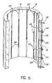
- the electrically conductive elements can then be arranged in the grooves over lengths and / or with different intervals, so as to define transverse zones electrically identifiable with respect to each other. It is thus possible to carry out a real electrical coding of the sub-assembly making it possible to locate with precision a leak of the liquid metal inside a relatively long sub-assembly.
- each of the electrically conductive elements is electrically connected by its two ends to terminals opening onto the external face of the shell.
- electrically conductive bars can be placed on the external face of the shell between some of said terminals so as to electrically connect several electrically conductive elements in series.
- the invention also relates to a device for detecting leaks of a liquid metal circulating in a circuit
- a device for detecting leaks of a liquid metal circulating in a circuit comprising one or more members such as a pipe or a valve, characterized in that it comprises several sub-assemblies assembled in pairs so surrounding the circuit and means for detecting a short circuit between the circuit and any of the electrically conductive elements.
- the latter can then define heating resistors capable of being connected to an appropriate current source for heating the circuit.
- the electrically conductive elements received in the grooves formed in one or more of the rigid shells are connected together to form neighboring loops connected to said means for detecting a short circuit and, possibly, at the source of voltage for heating the pipe.
- electrically conductive bars are arranged on the face external shells between some of said terminals of two neighboring sub-assemblies, so as to electrically connect in series electrically conductive elements of these sub-assemblies.
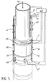
- a tubular and vertical pipe 10 has been shown in which a liquid metal circulates, for example in the direction of the arrow 12.
- the pipe 10 may constitute part of the secondary circuit of a breeder nuclear reactor, the liquid metal being then consisting of sodium.
- the pipe 10 is surrounded by a leak detection device designated by the general reference 14, comprising a number of sub-assemblies 16, one of which is shown in isolation in FIG. 2.
- Each sub-assembly 16 comprises a rigid shell 18 which is in the form of a hollow half-cylinder whose internal face is complementary to the external face of the pipe 10.
- the shell 18 is made of an electrically insulating material and rigid as it is, for example, fibers of a silico-aluminate (mineral wool) embedded in a stiffened reinforcement binder (suspension of colloidal silica and sodium silicate).
- the rigid shell 18 can be obtained either by drying, then baking the fibrous material preimpregnated with! E reinforcing binder in liquid form, or by sedimentation, the fibers then being suspended in a reinforcing liquid, then deposited by sedimentation. or by suction on a porous wall such as a canvas.
- the specific weight of the material constituting the shells is between 250 kg / m3 and 350 kg / m3. Dry rupture tests carried out on test pieces of width b (in cm) and thickness d (in cm) resting on two supports placed at a distance 1 (in cm) and the rupture of which is caused by a load W ( in kg) made it possible to determine that the dry rupture modulus of this material, defined by the , is between 50 kg / cm2 and 100 kg / cm2.
- open grooves 20 are formed on the inner face of the shell 18.
- the grooves 20 are helical, mutually parallel and regularly spaced and define an angle of about 45 ° relative to the axis of the shell 18.
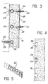
- Each of the grooves 20 receives an electrically conductive element 22 which can be constituted either by an electric wire wound in a helix as illustrated in FIG. 3, or by a metallic ribbon forming undulations as illustrated in FIGS. 4 and 5.
- the electrically conductive elements 22 are held in the grooves 20 by retaining means preferably constituted by a reduced width part 24 of the grooves, this part 24 being located between the internal face of the shell 18 and an enlarged part 26, in which the elements 22 are received.
- the grooves 20 may have in section a dovetail shape as illustrated in FIGS. 1 and 2.
- the part 26 receiving the elements 22 preferably has in section a shape complementary to the external envelope of these elements, so that the grooves 20 then have the shape shown in FIG. 3 when the elements 22 are son wound in a spiral, or a form of mortise as illustrated in fig.4 when the elements 22 are ribbons having undulations.
- each of the conductive elements 22 is electrically connected by its two ends to terminals 28 constituted by rods passing through suitable passages formed between the bottom of the grooves 20 and the external face of the shell 18.
- the rods 28 terminate at the outside of the shell 18 by threaded parts 30 allowing them to be connected at will with a neighboring rod or with a suitable external device.
- two neighboring rods 28 can be connected together by means of a conductive bar 32 fixed by nuts 34 screwed onto the threaded parts 30.
- the bars 32 can exclusively connect the adjacent rods 28 of a single sub-assembly 16, so as to define thereon two or more electrically conductive circuits capable of being connected by terminals 28 such as terminals 1- 2, 1'-2 'and 1 "-2" to means for detecting (not shown) a possible short circuit between the line 10 and each of these circuits.
- the operating principle of system 33 is based on the measurement of the insulation resistance by the conventional Wheatstone bridge method.
- a zero comparator circuit detects the tilting of the polarity when the insulation resistance produced by the grounding of a circuit leading to the terminals 28 by sodium is lowered.
- a potentiometer makes it possible to choose the detection threshold by moving the equilibrium point of the Wheatstone measuring bridge, for example between a few hundred ohms and 10,000 ohms.
- Each circuit or loop is tested in turn by means of a scanning device which triggers an alarm when the corresponding loop is faulty. This principle makes it possible to limit false alarms by eliminating transient parasitic faults. When the alarm is triggered, it remains maintained until the manual reset intervention even if the fault disappears.
- the terminals 1, 2 of each of the electrical circuits defined by this device are also connected to an appropriate current source (not shown) allowing d '' preheating the line 10 and heating the line and sodium in case of prolonged shutdown of the reactor.
- This heating is obtained by the Joule effect inside the electrically conductive elements 22 which also define heating resistors.
- the sub-assemblies 16 constituting the device 14 are assembled in pairs around the pipe 10, for example by means of straps 36 or by means of conductive or insulating bars 32 according to the configuration of the electrical circuits which it is desired to obtain .
- the sub-assemblies 16 successively disposed along the pipe 10 can also be connected to each other for example by means of conductive or insulating bars 32.
- the electrically conductive elements 22 are arranged in the grooves 20 on different lengths from one groove to another and / or with different intervals, so as to define coded transverse zones, and therefore electrically identifiable with respect to the other.
- the coded zones are produced by dividing the electrically conductive elements 22, as illustrated by way of example in FIG. 6, these elements being electrically connected together in series by means of rods 28 and conductive bars 32 of the same type as those which have been described above with reference to FIGS. 1 to 3.
- the zones thus defined on each of the sub-seeds 16 are all of the same length, which means that the lengths of the elements 22 and the intervals between two elements located in the same groove 20 or between an element and the end of the shell 18 are all multiples and submultiples of each other.
- the configuration of the electrical detection circuits constituted by the installation of the conductive bars 32 has preferably been defined taking into account the dimensions of each of the sub-assemblies 16, in order to allow as precise a location as possible of a leak possible occurring in the pipe 10.
- an electrical circuit limited to this sub-assembly will allow a relatively precise detection of the leak requiring the dismantling of this sub-assembly alone or the sub-assembly with which it surrounds the pipe 10.
- the length of the sub-assemblies 16 is one meter, an electrical circuit extending over two consecutive sub-assemblies 16 will make it possible to locate a possible leak with the same precision than in the previous hypothesis.
- the location of the leak can be made by coding, so that the configuration of the electrical circuits is less important.
- the subassemblies then preferably being intended horizontal pipes, or in the case of annular grooves, the subassemblies then preferably being intended for vertical pipes.
- Terminals 1 - 2, 1'-2 'or 1 "-2" being connected to the short-circuit detection system 33 between line 10 and each of these circuits, an alarm system such as a warning light or a audible alert is triggered and makes it possible to quickly locate the leak by knowing the circuit (s) concerned.
- terminals 1-2, 1'-2 ', etc. of each of the circuits formed by the electrically conductive elements 22 possibly connected by bars 32 are connected to a current source making it possible to heat the pipe 10 by Joule effect using the electrically conductive elements 22 as heating resistors, that these elements are present in the form of a wire wound in a helix as illustrated in fig. 3 or a metallic ribbon having undulations as illustrated in FIGS. 4 and 5.
- the invention is not limited to the embodiments which have just been described by way of examples, but incorporates all the variants.
- the invention also makes it possible to detect leaks from any other liquid metal.
- the shape and dimensions of the sub-assemblies 16 can be modified as a function of the shape and dimensions of the member of the circuit in which the liquid metal circulates, this member possibly being a pipe, a valve, etc., and can also be adapted to detect leaks of liquid metal contained in a storage member such as a tank.
- the electrically conductive elements can be kept spaced from the pipe or the tank by any retaining means other than making a part of reduced width on the open grooves, provided that this means does not obstruct the passage of the liquid metal. to the conductive elements in the event of a leak.
Description
L'invention concerne un sous-ensemble pour la détection de fuites d'un métal liquide circulant dans un organe d'un circuit tel qu'une conduite ou une vanne ou contenu dans un organe de stockage tel qu'un réservoir, ainsi qu'un dispositif de détection comprenant plusieurs sous-ensembles de ce type.The invention relates to a subassembly for detecting leaks of a liquid metal circulating in a member of a circuit such as a pipe or a valve or contained in a storage member such as a tank, as well as a detection device comprising several subsets of this type.
Dans certaines applications, et notamment dans les réacteurs nucléaires surrégénérateurs, un métal liquide tel que du sodium fondu circule dans des circuits. Pour des raisons de sécurite évidentes, en particulier lorsque le métal liquide est constitué par du sodium, il est nécessaire de pouvoir détecter rapidement et de façon précise l'existence de fuites de ce métal le long du circuit ou d'un réservoir qui le contient.In certain applications, and in particular in breeder nuclear reactors, a liquid metal such as molten sodium circulates in circuits. For obvious safety reasons, in particular when the liquid metal consists of sodium, it is necessary to be able to quickly and precisely detect the existence of leaks of this metal along the circuit or of a tank which contains it .
Afin de réaliser une telle détection, on a proposé un certain nombre de dispositifs. Ces dispositifs comprennent pour la plupart des éléments électriquement conducteurs, se présentant par exemple sous la forme de fils, de plaques ou de grilles, associés à un matériau support électriquement isolant interposé entre ces éléments électriquement conducteurs et la conduite dans laquelle circule le métal liquide. Le support en matériau isolant peut être constitué par exemple par un tissu de fils de silice ou par une couche de feutre perméable. Selon les dispositifs, la fuite du métal liquide est détectée, soit par l'établissement d'un contact électrique entre deux éléments électriquement conducteurs voisins, soit par l'établissement d'un contact électrique entre un ou plusieurs de ces éléments électriquement conducteurs et la conduite. Dans tous les cas, la détection n'intervient que lorsque le métal liquide provenant de la fuite a traversé le support en matériau électriquement isolant, ce qui n'est réalisé généralement qu'au bout d'un temps relativement long pouvant atteindre plusieurs minutes. Ce temps de réponse n'est évidemment pas satisfaisant, notamment lorsque le métal liquide est constitué par du sodium, en raison du risque d'incendie créé par l'existence d'une fuite. En outre, ces dispositifs connus sont fragiles et d'un maniement délicat, surtout lorsqu'ils travaillant à une température relativement élevée comme cela est le cas lorsqu'ils entourent des conduites dans lesquelles circule du sodium liquide.In order to carry out such detection, a number of devices have been proposed. These devices comprise for the most part electrically conductive elements, being for example in the form of wires, plates or grids, associated with an electrically insulating support material interposed between these electrically conductive elements and the pipe in which the liquid metal circulates. The support of insulating material can be constituted for example by a fabric of silica threads or by a layer of permeable felt. According to the devices, the leakage of the liquid metal is detected, either by the establishment of an electrical contact between two neighboring electrically conductive elements, or by the establishment of an electrical contact between one or more of these electrically conductive elements and the conduct. In all cases, detection takes place only when the liquid metal coming from the leak has passed through the support made of electrically insulating material, which is generally not achieved until after a relatively long time which can reach several minutes. This response time is obviously not satisfactory, especially when the liquid metal consists of sodium, due to the risk of fire created by the existence of a leak. In addition, these known devices are fragile and difficult to handle, especially when working at a relatively high temperature as is the case when they surround pipes in which liquid sodium circulates.
En outre, le document FR-A-2 382 685 décrit un détecteur de fuites pour une canalisation contenant du métal liquide et entourée à distance d'une enveloppe. Cette enveloppe comporte à son poùnt le plus bas une rigole renfermant des fils isolés les une des autres et de l'enveloppe, l'isolation des fils étant interrompue de.telle manière que de métal liquide s'echap- pant de la canalisation et secuilli dans la rigole, établisse une liaison électrique entre les fils.In addition, document FR-A-2 382 685 describes a leak detector for a pipe containing liquid metal and surrounded at a distance from an envelope. This envelope has at its lowest point a channel containing wires isolated from each other and from the envelope, the insulation of the wires being interrupted in such a way that liquid metal escapes from the pipe and is secured in the channel, establish an electrical connection between the wires.
L'invention a pour but la réalisation d'un dispositif de détection de fuites d'un métal liquide ne présentant pas les défauts des dispositifs connus et se caractérisant notamment par un temps de réponse particulièrement court et par un maniement extrêmement facile.The object of the invention is to produce a device for detecting leaks of a liquid metal which does not have the faults of known devices and which is characterized in particular by a particularly short response time and by extremely easy handling.
Dans ce but, il est proposé un sous-ensemble pour la détection de fuites d'un métal liquide circulant dans un organe d'un circuit tel qu'une conduite ou une vanne ou contenu dans un organe de stockage tel qu'un réservoir, comprenant des éléments électriquement conducteurs disposés à l'intérieur d'un matériau électriquement isolant, caractérisé en ce que ledit matériau isolant est constitué par une coquille rigide dont la face interne épouse la face externe dudit organe, des rainures ouvertes étant formées sur la face interne de la coquille pour recevoir lesdits éléments électriquement conducteurs, les rainures présentant en section une partie élargie, éloignée de la face interne de la coquille, recevant les éléments électriquement conducteurs, et une partie de largeur réduite, située entre la partie élargie et la face interne de la coquille et maintenant les éléments électriquement conducteurs espacés de ladite face interne.For this purpose, a sub-assembly is proposed for detecting leaks of a liquid metal circulating in a member of a circuit such as a pipe or a valve or contained in a storage member such as a reservoir, comprising electrically conductive elements arranged inside an electrically insulating material, characterized in that said insulating material consists of a rigid shell whose internal face matches the external face of said member, open grooves being formed on the internal face of the shell for receiving said electrically conductive elements, the grooves having in section an enlarged part, distant from the internal face of the shell, receiving the electrically conductive elements, and a part of reduced width, located between the enlarged part and the internal face of the shell and maintaining the electrically conductive elements spaced from said internal face.
En raison de la disposition des éléments électriquement conducteurs dans des rainures ouvertes en vis-à-vis de la conduite, il est clair que toute fuite de métal liquide se produisant sur celle-ci aura pour conséquence immédiate la mise en contact électrique par ce métal de l'un au moins des éléments électriquement conducteurs et de la conduite. En outre, la réalisation du dispositif sous forme de coquille rigide permet une manutention, un transport et un assemblage de ces sous-ensembles beaucoup plus facile que pour les dispositifs antérieurs connus.Due to the arrangement of the electrically conductive elements in open grooves opposite the pipe, it is clear that any leakage of liquid metal occurring on the latter will have the immediate consequence of electrical contact by this metal at least one of the electrically conductive elements and the pipe. In addition, the realization of the device in the form of a rigid shell allows handling, transport and assembly of these subassemblies much easier than for known prior devices.
Selon une autre caractéristique de l'invention, la partie élargie des rainures présente en section une forme complémentaire de l'enveloppe externe des éléments électriquement conducteurs.According to another characteristic of the invention, the enlarged part of the grooves has in section a shape complementary to the external envelope of the electrically conductive elements.
Selon une première variante de l'invention, les éléments électriquement conducteurs sont des fils métalliques enroulés en hélice à l'intérieur des rainures.According to a first variant of the invention, the electrically conductive elements are metal wires wound in a helix inside the grooves.
Selon une seconde variante, les éléments électriquement conducteurs sont des rubans métalliques formant des ondulations à l'intérieur des rainures.According to a second variant, the electrically conductive elements are metal strips forming corrugations inside the grooves.
Conformément à une autre caractéristique secondaire de l'invention, la coquille rigide est réalisée en un matériau comprenant des fibres noyées dans un liant de renforcement rigidifié.According to another secondary characteristic of the invention, the rigid shell is made of a material comprising fibers embedded in a stiffened reinforcing binder.
Conformément à un mode de réalisation particulier de l'invention, un tel sous-ensemble pour la détection de fuites d'un métal liquide circulant dans une conduite est caractérisé en ce qLe la coquille rigide se présente sous la forme d'un demï-cylindre creux, les rainures étant hélicoidales, parallèles entre elles et régulièrement espacées. De préférence, les rainures sont alors inclinées sensiblement à 45° par rapport à l'axe de la coquille, ce qui permet de disposer le sous-ensemble aussi bien sur une conduite verticale que sur une conduite horizontale ou oblique.According to a particular embodiment of the invention, such a subset for the detection of leaks of liquid metal circulating in a conduit is characterized in that L e q rigid shell is in the shape of a half -hollow cylinder, the grooves being helical, parallel to each other and regularly spaced. Preferably, the grooves are then inclined substantially at 45 ° relative to the axis of the shell, which makes it possible to arrange the sub-assembly as well on a vertical pipe as on a horizontal or oblique pipe.
Conformément à un autre mode de réalisation de l'invention, un sous-ensemble pour la détection de fuites d'un métal liquide circulant dans une conduite, est caractérisé en ce que la coquille rigide se présente sous la forme d'un demi-cylindre creux, les rainures étant parallèles à l'axe du demi-cylindre et régulièrement espacées. Les éléments électriquement conducteurs peuvent alors être disposés dans les rainures sur des longueurs et/ou avec des intervalles différents, de façon à définir des zones transversales identifiables électriquement les unes par rapport aux autres. Il est ainsi possible de réaliser un véritable codage électrique du sous-ensemble permettant de localiser avec précision une fuite du métal liquide à l'intérieur d'un sous-ensemble relativement long.According to another embodiment of the invention, a sub-assembly for the detection of leaks of a liquid metal flowing in a pipe, is characterized in that the rigid shell is in the form of a half-cylinder hollow, the grooves being parallel to the axis of the half-cylinder and regularly spaced. The electrically conductive elements can then be arranged in the grooves over lengths and / or with different intervals, so as to define transverse zones electrically identifiable with respect to each other. It is thus possible to carry out a real electrical coding of the sub-assembly making it possible to locate with precision a leak of the liquid metal inside a relatively long sub-assembly.
Selon une autre caractéristique de l'invention, chacun des éléments électriquement conducteurs est connecté électriquement par ses deux extrémités à des bornes débouchant sur la face externe de la coquille. Dans ce cas, des barrettes électriquement conductrices peuvent être disposées sur la face externe de la coquille entre certaines desdites bornes de façon à raccorder électriquement en série plusieurs éléments électriquement conducteurs.According to another characteristic of the invention, each of the electrically conductive elements is electrically connected by its two ends to terminals opening onto the external face of the shell. In this case, electrically conductive bars can be placed on the external face of the shell between some of said terminals so as to electrically connect several electrically conductive elements in series.
L'invention concerne également un dispositif de détection de fuites d'un métal liquide circulant dans un circuit comprenant un ou plusieurs organes tels qu'une conduite ou une vanne, caractérisé en ce qu'il comprend plusieurs sous-ensembles assemblés par paires de façon à entourer le circuit et des moyens pour détecter un courtcircuit entre le circuit et l'un quelconque des éléments électriquement conducteurs. Ces derniers peuvent alors définir des résistances chauffantes susceptibles d'être connectées à une source de courant appropriée pour assurer le chauffage du circuit. Cette caractéristique permet d'éviter d'avoir recours à deux dispositifs séparés, notamment dans les réacteurs nucléaires surrégénateurs refroidis par du sodium liquide, pour détecter les fuites de sodium et pour assurer le préchauffage du circuit ou le chauffage du circuit et du sodium dans le cas où celui-ci se serait solidifié par suite d'un arrêt prolongé du réacteur.The invention also relates to a device for detecting leaks of a liquid metal circulating in a circuit comprising one or more members such as a pipe or a valve, characterized in that it comprises several sub-assemblies assembled in pairs so surrounding the circuit and means for detecting a short circuit between the circuit and any of the electrically conductive elements. The latter can then define heating resistors capable of being connected to an appropriate current source for heating the circuit. This feature makes it possible to avoid having to use two separate devices, in particular in nuclear reactors cooled by liquid sodium, to detect sodium leaks and to ensure the preheating of the circuit or the heating of the circuit and sodium in the case it would have solidified due to a prolonged shutdown of the reactor.
Conformément à une autre caractéristique de l'invention, les éléments électriquement conducteurs reçus dans les rainures formées dans une ou plusieurs des coquilles rigides sont raccordés entre eux pour former des boucles voisines connectées auxdits moyens pour détecter un courtcircuit et, éventuellement, à la source de tension permettant d'assurer le chauffage de la conduite.According to another characteristic of the invention, the electrically conductive elements received in the grooves formed in one or more of the rigid shells are connected together to form neighboring loops connected to said means for detecting a short circuit and, possibly, at the source of voltage for heating the pipe.
Selon une variante de l'invention, lorsque chacun des éléments électriquement conducteurs d'un même sous-ensemble est connecté électriquement par ses deux extrémités à des bornes débouchant sur la face externe de la coquille correspondante, des barrettes électriquement conductrices sont disposées sur la face externe des coquilles entre certaines desdites bornes de deux sous-ensembles voisins, de façon à raccorder électriquement en série des éléments électriquement conducteurs de ces sous-ensembles.According to a variant of the invention, when each of the electrically conductive elements of the same subassembly is electrically connected by its two ends to terminals opening onto the external face of the corresponding shell, electrically conductive bars are arranged on the face external shells between some of said terminals of two neighboring sub-assemblies, so as to electrically connect in series electrically conductive elements of these sub-assemblies.
On décrira maintenant, à titre d'exemple non limitatif, un mode de réalisation particulier de l'invention en se référant aux dessins annexés dans lasquels:
- - la fig. 1 est une vue en perspective illustrant un dispositif de détection de fuites d'un métal liquide circulant dans une conduite, ce dispositif comprenant plusieurs sous-ensembles réalisés conformément à l'invention,
- - la fig. 2 est une vue en perspective éclatée de l'un des sous-ensembles constituant le dispositif représenté sur la fig. 1, montrant notamment la face interne de ce sous-ensemble,
- - la fig. 3 est une vue en coupe longitudinale du sous-ensemble représenté sur la fig. 2 illustrant une première variante de l'invention, dans laquelle les éléments électriquement conducteurs sont constitués par des fils enroulés en hélice,
- - la fig. 4 est une vue en coupe comparable à la fig. 3 illustrant une seconde variante de l'invention, dans laquelle les éléments électriquement conducteurs sont constitués par des rubans métalliques formant des ondulations,
- - la fig. 5 est une vue en perspective représentant isolément l'un des éléments électriquement conducteurs de la variante de la fig. 4, et
- - la fig. 6 est une vue en perspective éclatée représentant un sous-ensemble dont les éléments électriquement conducteurs sont . disposés de façon à réaliser un codage électrique.
- - fig. 1 is a perspective view illustrating a device for detecting leaks of a liquid metal flowing in a pipe, this device comprising several sub-assemblies produced in accordance with the invention,
- - fig. 2 is an exploded perspective view of one of the sub-assemblies constituting the device shown in FIG. 1, showing in particular the internal face of this sub-assembly,
- - fig. 3 is a view in longitudinal section of the sub-assembly shown in FIG. 2 illustrating a first variant of the invention, in which the electrically conductive elements consist of wires wound in a helix,
- - fig. 4 is a sectional view comparable to FIG. 3 illustrating a second variant of the invention, in which the electrically conductive elements consist of metal strips forming corrugations,
- - fig. 5 is a perspective view in isolation representing one of the electrically conductive elements of the variant of FIG. 4, and
- - fig. 6 is an exploded perspective view showing a sub-assembly whose electrically conductive elements are. arranged to perform electrical coding.
Sur la fig. 1, on a représenté une conduite tubulaire et verticale 10 dans laquelle circule un métal liquide, par exemple dans le sens de la- flèche 12. La conduite 10 peut constituer une partie du circuit secondaire d'un réacteur nucléaire surrégénérateur, le métal liquide étant alors constitué par du sodium.In fig. 1, a tubular and
Conformément à l'invention, la conduite 10 est entourée par un dispositif de détection de fuites désigné par la référence générale 14, comprenant un certain nombre de sous-ensembles 16 dont l'un est représenté isolément sur la fig. 2. Chaque sous-ensemble 16 comprend une coquille rigide 18 qui se présente sous la forme d'un demi-cylindre creux dont la face interne est complémentaire de la face externe de la conduite 10. La coquille 18 est réalisée en un matériau électriquement isolant et rigide telque, par exemple, des fibres d'un silico-aluminate (laine minérale) noyées dans un liant de renforcement rigidifié (suspension de silice colloïdale et de silicate de soude). Dans ce cas, la coquille rigide 18 peut être obtenue soit par séchage, puis cuisson du matériau fibreux préimprégné par !e liant de renforcement sous forme liquide, soit par sédimentation, les fibres étant alors suspendues dans un liquides de renforcement, puis déposées par sédimentation ou par aspiration sur une paroi poreuse telle qu'une toile.According to the invention, the
A titre d'information, on notera que le poids spécifique du matériau constituant les coquilles est compris entre 250 kg/m3 et 350 kg/m3. Des essais de rupture à sec effectués sur des éprouvettes de largeur b (en cm) et d'épaisseur d (en cm) reposant sur deux supports placés à une distance 1 (en cm) et dont la rupture est provoquée par une charge W (en kg) ont permis de déterminer que le module de rupture à sec de ce matériau, défini par la formulare ![]()
![]()
Comme le montre en particulier la fig. 2, des rainures ouvertes 20 sont formées sur la face interne de la coquille 18. De préférence, les rainures 20 sont hélicdidales, parallèles entre elles et régulièrement espacées et définissent un angle d'environ 45° par rapport à l'axe de la coquille 18. Chacune des rainures 20 reçoit un élément électriquement conducteur 22 qui peut être constitué, soit par un fil électrique enroulé en hélice comme l'illustre la fig. 3, soit par un ruban métallique formant des ondulations comme l'illustrent les fig. 4 et 5. Les éléments électriquement conducteurs 22 sont maintenus dans les rainures 20 par des moyens de retenue constitués de préférence par une partie de largeur réduits 24 des rainures, cette partie 24 étant située entre la face interne de la coquille 18 et une partie élargie 26, dans laquelle sont reçus les éléments 22. Les rainures 20 peuvent présenter en section une forme de queue d'aronde comme l'illustrent les fig. 1 et 2. Cependant, la partie 26 recevant les éléments 22 présente de préférence en section une forme complémentaire de l'enveloppe externe de ces éléments, de sorte que les rainures 20 présentent alors la forme représentée sur la fig. 3 lorsque les éléments 22 sont des fils enroulés en spirale, ou une forme de mortaise comme l'illustre la fig.4 lorsque les éléments 22 sont des rubans présentant des ondulations.As shown in particular in fig. 2,
Comme l'illustre notamment la fig. 2, chacun des éléments conducteurs 22 est connecté électriquement par ses deux extrémités à des bornes 28 constituées par des tiges traversant des passages appropriés formés entre le fond des rainures 20 et la face externe de la coquille 18. Les tiges 28 se terminent à l'extérieur de la coquille 18 par des parties filetées 30 permettant de les raccorder à volonté avec une tige voisine ou avec un dispositif externe approprié. Ainsi, deux tiges 28 voisines peuvent être raccordées entre elles au moyen d'une barrette conductrice 32 fixée par des écrous 34 vissés sur les parties filetées 30.As illustrated in particular in FIG. 2, each of the
Comme l'illustre la fig. 2, les barrettes 32 peuvent relier exclusivement les tiges 28 adjacentes d'un seul sous-ensemble 16, de façon à définir sur celui-ci deux ou plusieurs circuits électriquement conducteurs susceptibles d'être raccordés par des bornes 28 telles que les bornes 1-2, 1'-2' et 1"-2" à des moyens de détection (non représentés) d'un court-circuit éventuel entre la conduite 10 et chacun de ces circuits.As illustrated in fig. 2, the
Bien entendu, et comme l'illustre la fig. 1, les barrettes 32 peuvent également être utilisées pour raccorder électriquement les éléments électriquement conducteurs de deux sous-ensembles 16 voisins, et pour relier mécaniquement ces sous-ensembles entre eux. Des circuits très variés peuvent ainsi être constitués au moyen des éléments électriquement conducteurs 22 et des barretts 32 selon la structure particulière du circuit à surveiller. Ainsi, les éléments électriquement conducteurs d'un sous-ensemble 16 ou de plusieurs sous-ensembles successifs peuvent être connectés deux par deux en forme de boucles, de telle sorte que les bornes 28, telles que les bornes 1-2, 1'-2' et 1"-2" sur la fig. 1, des circuits ainsi formés, se trouvent situés à la même extrémité de l'un des sous-ensembles 16 ou sur un même côté de celui-ci. Quels que soient les circuits électriques ainsi constitués à l'intérieur du dispositif 14, les bornes 28 de ces circuits, telles que 1-2, 1'-2' ou 1"-2" sur la fig. 1, sont raccordées à un système de détection de défauts d'isolement 33 qui est également en contact électrique avec la conduite 10, de façon à détecter un éventuel courtcircuit entre cette conduite et l'un quelconque des circuits. La surveillance peut ainsi être effectuée soit en continu, soit par balayage. Le système de détection électronique 33 assure les fonctions suivantes:
- - vérification de la continuité de chacun des circuits aboutissent aux bornes 28,
- - surveillance de l'isolement de chaque circuit par rapport à la conduite 10,
- - déclenchement d'une alarme en cas de défaut.
- - verification of the continuity of each of the circuits leads to
terminals 28, - - monitoring of the insulation of each circuit with respect to
line 10, - - triggering of an alarm in the event of a fault.
Le principe de fonctionnement du système 33 est basé sur la mesure, de la résistance d'isolement par la méthode classique du pont de Wheatstone. Un circuit comparateur de zéro détecte le basculement de la polarité lors de l'abaissement de la résistance d'isolement produit par la mise à la masse d'un circuit aboutissant aux bornes 28 par le sodium. Un potentiomètre permet de choisir le seuil de détection par déplacement du point d'équilibre du pont de mesure de Wheatstone, par exemple entre quelques centaines d'ohms et 10 000 ohms. Chaque circuit ou boucle est testé à tour de rôle au moyen d'un dispositif de balayage qui déclenche une alarme lorsque la boucle correspondante est en défaut. Ce principe permet de limiter les fausses alarmes en éliminant les défauts transitoires de type parasite. Lorsque l'alarme est déclenchée, elle reste maintenue jusqu'à l'intervention manuelle de réarmement même si le défaut disparaît. Simultanément, lorsque le dispositif de détection 14 est monté sur une conduite 10 dans laquelle circule du sodium liquide, les bornes 1, 2 de chacun des circuits électriques définis par ce dispositif sont également raccordées à une source de courant appropriée (non représentée) permettant d'assurer le préchauffage de la conduite 10 et le chauffage de la conduite et du sodium en cas d'arrêt prolongé du réacteur. Ce chauffage est obtenu par effet Joule à l'intérieur des éléments électriquement conducteurs 22 qui définissent également des résistances chauffantes.The operating principle of
Comme l'illustre en particulier la fig. 1, les sous-ensembles 16 constituant le dispositif 14 sont assemblés deux à deux autour de la conduite 10, par exemple au moyen de cerclages 36 ou au moyen de barrettes 32 conductrices ou isolantes selon la configuration des circuits électriques que l'on désire obtenir. De même, les sous-ensembles 16 disposés successivement le long de la conduite 10 peuvent également être raccordés les uns aux autres par exemple au moyen de barrettes 32 conductrices ou isolantes.As illustrated in particular in fig. 1, the
Dans le mode de réalisation de la fig. 6, les rainures ouvertes 20 formées dans les sous-ensembles 16, dont l'un est représenté en coupe le long d'une des rainures, s'étendent parallèlement à l'axe du demi-cylindre défini par les coquilles 18. En outre, les éléments électriquement conducteurs 22 sont disposés dans les rainures 20 sur des longueurs différentes d'une rainure à l'autre et/ou avec des intervalles différents, de façon à définir des zones transversales codées, et donc identifiables électriquement les unes par rapport aux autres. Ainsi, si une fuite de sodium se produit dans la conduite au niveau de l'une ou de plusieurs de ces zones, un contact électrique s'établit entre la conduite et les éléments conducteurs 22 situés dans ces zones, de sorte que la détection des contacts électriques ainsi établis permet, connaissant le schéma de répartition des zones codées le long de la conduite, de localiser avec toute la précision souhaitée la fuite ainsi détectée. Pratiquement, les zones codées sont réalisées en fractionnant les éléments électriquement conducteurs 22, comme l'illustre à titre d'exemple la fig. 6, ces éléments étant reliés électriquement entre eux en série au moyen de tiges 28 et de barrettes conductrices 32 du même type que celles qui ont été décrites précédemment en se référant aux fig. 1 à 3. De préférence, les zones ainsi définies sur chacun des sousen- sembles 16 sont toutes de même longueur, ce qui signifie que les longueurs des éléments 22 et les intervalles entre deux éléments situés dans une même rainure 20 ou entre un élément et l'extrémité de la coquille 18 sont tous des multiples et des sous-multiples les uns des autres.In the embodiment of FIG. 6, the
Le dispositif qui vient d'être décrit en se référant aux fig. 1 à 6 fonctionne de la façon suivante.The device which has just been described with reference to FIGS. 1 to 6 works as follows.
Lorsque les sous-ensembles 16 ont été assemblés et montés sur la conduite 10, comme l'illustre la fig. 1, la configuration des circuits électriques de détection constitués par la mise en place des barrettes conductrices 32 a été de préférence définie en tenant compte des dimensions de chacun des sous-ensembles 16, afin de permettre une localisation aussi précise que possible d'une fuite éventuelle se produisant dans la conduite 10. Ainsi, si la longueur de chacun des sous-ensembles 16 est de deux mètres, un circuit électrique limité à ce sous-ensemble permettra une détection relativement précise de la fuite nécessitant le démontage de ce sous-ensemble seul ou du sous-ensemble avec lequel il entoure la conduite 10. Si la longueur des sous-ensembles 16 est d'un mètre, un circuit électrique s'étendant sur deux sous-ensembles 16 consécutifs permettra de localiser une fuite éventuelle avec la même précision que dans l'hypothèse précédente. Bien entendu, dans le cas de la fig. 6, la localisation de la fuite peut être faite grâce au codage, de sorte que la configuration des circuits électriques est moins importante.When the sub-assemblies 16 have been assembled and mounted on the
Lorsqu'une fuite de métal liquide se produit dans la conduite 10, en raison de la disposition des éléments conducteurs 22 dans les rainures ouvertes 20, le métal liquide qui s'échappe de la fuite vient presque instantanément en contact avec l'un des éléments 22, pourvu que ces éléments soient suffisamment rapprochés. En outre, la configuration hélicôidale des rainures 20 (fig. 21) permet, en raison des forces de gravité agissant sur le métal liquide qui s'échappe de la fuite, de garantir une détection rapide de celle-ci aussi bien sur une conduite horizontale que sur une conduite verticale ou oblique. Cependant, il va de soi que l'invention n'est pas limitée à ce mode de réalisation particulier et s'applique, par exemple, également au cas de rainures longitudinales (fig. 6), les sous-ensembles étant alors destinés de préférence à des conduites horizontales, ou au cas de rainures annulaires, les sous-ensembles étant alors destinés de préférence à des conduites verticales. Dans tous les cas, étant donné que le métal liquide n'a pas-à traverser de couches isolantes avant de venir en contact avec les éléments électriquement conducteurs 22, le contact électrique entre la conduite 10 et ces éléments s'établit en quelques secondes. Les bornes 1 - 2, 1'-2' ou 1"-2" étant raccordées au système de détection de court-circuit 33 entre la conduite 10 et chacun de ces circuits, un système d'alarme tel qu'un voyant ou une alerte sonore se déclenche et permet de localiser rapidement la fuite par la connaissance du ou des circuits concernés.When a liquid metal leak occurs in the
Simultanément, et comme il a été mentionné précédemment, les bornes 1-2, 1'-2', etc. de chacun des circuits constitués par les éléments électriquement conducteurs 22 reliés éventuellement par des barrettes 32 sont connectées à une source de courant permettant de chauffer la conduite 10 par effet Joule en utilisant les éléments électriquement conducteurs 22 comme des résistances chauffantes, que ces éléments se présentent sous la forme d'un fil métallique enroulé en hélice comme l'illustre la fig. 3 ou d'un ruban métallique présentant des ondulations comme l'illustrent les fig. 4 et 5.At the same time, and as mentioned previously, terminals 1-2, 1'-2 ', etc. of each of the circuits formed by the electrically
Bien entendu, l'invention n'est pas limitée aux modes de réalisation qui viennent d'être décrits à titre d'exemples, mais en incorpore toutes les variantes. Ainsi, et bien qu'elle soit particulièrement adaptée à la détection des fuites de sodium, l'invention permet également de détecter les fuites de tout autre métal liquide. De même, la forme et les dimensions des sous-ensembles 16 peuvent être modifiées en fonction de la forme et des dimensions de l'organe du circuit dans lequel circule le métal liquide, cet organe pouvant être une conduite, une vanne, etc., et peuvent également être adaptées pour détecter des fuites de métal liquide contenues dans un organe de stockage tel qu'un réservoir. Enfin, les éléments électriquement conducteurs peuvent être maintenus espacés de la conduite ou du réservoir par tout moyen de retenue autre que la réalisation d'une partie de largeur réduite sur les rainures ouvertes, pourvu que ce moyen n'entrave pas le passage du métal liquide jusqu'aux éléments conducteurs en cas de fuite.Of course, the invention is not limited to the embodiments which have just been described by way of examples, but incorporates all the variants. Thus, and although it is particularly suitable for detecting sodium leaks, the invention also makes it possible to detect leaks from any other liquid metal. Similarly, the shape and dimensions of the
Claims (15)
Applications Claiming Priority (2)
| Application Number | Priority Date | Filing Date | Title |
|---|---|---|---|
| FR7911142A FR2455707A1 (en) | 1979-05-03 | 1979-05-03 | SUB-ASSEMBLY FOR THE DETECTION OF LEAKS OF A LIQUID METAL AND DETECTION DEVICE COMPRISING SEVERAL SUB-ASSEMBLIES OF THIS TYPE |
| FR7911142 | 1979-05-03 |
Publications (2)
| Publication Number | Publication Date |
|---|---|
| EP0018916A1 EP0018916A1 (en) | 1980-11-12 |
| EP0018916B1 true EP0018916B1 (en) | 1982-12-08 |
Family
ID=9224967
Family Applications (1)
| Application Number | Title | Priority Date | Filing Date |
|---|---|---|---|
| EP80400599A Expired EP0018916B1 (en) | 1979-05-03 | 1980-04-30 | Sub-unit for detecting liquid-metal leaks and detection device comprising several sub-units of this type |
Country Status (6)
| Country | Link |
|---|---|
| US (1) | US4332170A (en) |
| EP (1) | EP0018916B1 (en) |
| JP (1) | JPS5612531A (en) |
| DE (1) | DE3061257D1 (en) |
| ES (1) | ES8200754A1 (en) |
| FR (1) | FR2455707A1 (en) |
Families Citing this family (27)
| Publication number | Priority date | Publication date | Assignee | Title |
|---|---|---|---|---|
| JPS5713397A (en) * | 1980-06-30 | 1982-01-23 | Tokyo Shibaura Electric Co | Lining tank and its manufacture |
| DE3045257A1 (en) * | 1980-12-01 | 1982-06-03 | Friedhelm 5893 Kierspe Schmitz | CONTROL SYSTEM FOR LEAK DETECTING PIPELINES |
| JPS57197456A (en) * | 1981-05-29 | 1982-12-03 | Toshiba Corp | Metallic ion detector |
| US4673652A (en) * | 1982-10-12 | 1987-06-16 | Baker Oil Tools, Inc. | Method of testing and reconditioning insulating tubular conduits |
| US4673926A (en) * | 1985-02-12 | 1987-06-16 | Gorman Walter T | Liquid containment and leak detection system |
| GB9000389D0 (en) * | 1990-01-08 | 1990-03-07 | Ici Plc | Steam reforming |
| US5072622A (en) * | 1990-06-04 | 1991-12-17 | Roach Max J | Pipeline monitoring and leak containment system and apparatus therefor |
| US5190069A (en) * | 1992-04-27 | 1993-03-02 | Richards Raymond C | Apparatus and method for detecting leaks |
| US5440917A (en) * | 1994-04-28 | 1995-08-15 | Glenn Smith | Leak detector |
| US5561418A (en) * | 1994-09-22 | 1996-10-01 | United States Of America As Represented By The Secretary Of The Navy | Leak detector for conductive liquid boiler |
| US6112579A (en) * | 1997-08-25 | 2000-09-05 | Tryba; Stephen A. | Fluid leakage sensors |
| US6634388B1 (en) | 1998-07-22 | 2003-10-21 | Safetyliner Systems, Llc | Annular fluid manipulation in lined tubular systems |
| US6523574B1 (en) | 1998-07-29 | 2003-02-25 | Safetyliner Systems, Llc | Insertion of liners into host tubulars by fluid injection |
| FR2826726B1 (en) * | 2001-06-29 | 2004-01-16 | Ttk | DIGITAL DEVICE FOR DETECTING AND LOCATING LIQUID LEAKS |
| KR20030074855A (en) * | 2002-03-14 | 2003-09-22 | (주)와콘 | Liquid pipe for detecting water leakage and establishing method |
| JP5499395B2 (en) * | 2009-03-09 | 2014-05-21 | 学校法人日本大学 | Leak detection pipe and leak detection device |
| FR2953270B1 (en) * | 2009-11-30 | 2013-02-22 | Areva | TUBULAR CANALIZATION FOR TRANSPORTING SODIUM LIQUID |
| US8371747B2 (en) * | 2010-07-16 | 2013-02-12 | Petroleum Analyzer Company, Lp | Detecting a short in an apparatus and method for determining the thermal stability of fluids |
| FR2964456B1 (en) * | 2010-09-08 | 2013-05-10 | Commissariat Energie Atomique | DEVICE FOR DETECTING LEAKAGE AND COATING OF TRANSPORTATION MEMBER OR STORAGE OF FLUID COMPRISING SAID DETECTION DEVICE |
| US20130333447A1 (en) * | 2012-06-15 | 2013-12-19 | Thomas Arthur White | Leakage detection |
| US9671068B2 (en) * | 2013-11-18 | 2017-06-06 | Mohammed Zulfiquar | Pipeline leakage protection vault system |
| US10268165B2 (en) * | 2014-11-05 | 2019-04-23 | The Trustees Of Princeton University | Electrical detector for liquid metal leaks |
| RU2599403C1 (en) * | 2015-06-04 | 2016-10-10 | Акционерное Общество "Атомэнергопроект" | Device for detecting leakage in pipelines |
| TWM573429U (en) * | 2017-10-11 | 2019-01-21 | 訊凱國際股份有限公司 | Fluid leak detector |
| CN109887626A (en) * | 2019-01-09 | 2019-06-14 | 中国原子能科学研究院 | A kind of detachable heat insulating block of integrated sodium leakage detecting function |
| US20220112988A1 (en) * | 2020-10-08 | 2022-04-14 | Saudi Arabian Oil Company | Hydrocarbon leak detecting devices and methods of detecting hydrocarbon leaks |
| CN113739083B (en) * | 2021-10-18 | 2023-03-14 | 湖南桂阳金煌管道燃气有限公司 | Detection apparatus for gas pipeline breaks gas leakage |
Family Cites Families (15)
| Publication number | Priority date | Publication date | Assignee | Title |
|---|---|---|---|---|
| DE579184C (en) * | 1931-04-08 | 1933-06-22 | Berthold Jenewein Dr Ing | Moisture indicator for insulation |
| GB606284A (en) * | 1951-01-09 | 1948-08-11 | Clifford Stuart Steadman | Improvements in or relating to heat exchange devices |
| US2759175A (en) * | 1954-03-12 | 1956-08-14 | Thomas R Spalding | Leak detector for pipe joint |
| BE622516A (en) * | 1961-09-19 | |||
| FR1377519A (en) * | 1963-09-25 | 1964-11-06 | Method for detecting leaks in a liquid line and device for applying this method | |
| US3721898A (en) * | 1968-12-04 | 1973-03-20 | P Dragoumis | Apparatus for detecting leakage from or rupture of pipes and other vessels containing fluid under pressure |
| US3721970A (en) * | 1971-10-06 | 1973-03-20 | Atomic Energy Commission | Alkali metal leak detector |
| DE2304368A1 (en) * | 1973-01-26 | 1974-08-01 | Hansen Neuerburg Gmbh | PIPING WITH AN ELECTRICAL SAFETY DEVICE |
| JPS5193274A (en) * | 1975-02-14 | 1976-08-16 | ||
| JPS5222998A (en) * | 1975-08-15 | 1977-02-21 | Hitachi Ltd | Liquid metal leakage detecting device |
| JPS5357897A (en) * | 1976-11-05 | 1978-05-25 | Toshiba Corp | Leakage detector of electroconductive fluid |
| DE2709468A1 (en) * | 1977-03-04 | 1978-09-07 | Interatom | LEAK DETECTION FOR LIQUID METAL PIPING |
| US4143540A (en) * | 1977-12-27 | 1979-03-13 | Continental Oil Company | Method of preventing corrosion of joints of steel structures submerged in corrosive media |
| FR2455739A2 (en) * | 1978-05-11 | 1980-11-28 | Carbonisation Entr Ceram | Detection of leaks of liq. metal - by coded locally, electrically conductive fabric woven from refractory isolating mineral threads |
| JPS5594130A (en) * | 1979-01-10 | 1980-07-17 | Toshiba Corp | Sodium leakage detector |
-
1979
- 1979-05-03 FR FR7911142A patent/FR2455707A1/en active Granted
-
1980
- 1980-04-29 US US06/144,915 patent/US4332170A/en not_active Expired - Lifetime
- 1980-04-30 EP EP80400599A patent/EP0018916B1/en not_active Expired
- 1980-04-30 DE DE8080400599T patent/DE3061257D1/en not_active Expired
- 1980-05-02 ES ES491106A patent/ES8200754A1/en not_active Expired
- 1980-05-06 JP JP5877480A patent/JPS5612531A/en active Granted
Also Published As
| Publication number | Publication date |
|---|---|
| ES491106A0 (en) | 1981-11-01 |
| JPH0125411B2 (en) | 1989-05-17 |
| JPS5612531A (en) | 1981-02-06 |
| FR2455707A1 (en) | 1980-11-28 |
| US4332170A (en) | 1982-06-01 |
| EP0018916A1 (en) | 1980-11-12 |
| FR2455707B1 (en) | 1983-01-21 |
| DE3061257D1 (en) | 1983-01-13 |
| ES8200754A1 (en) | 1981-11-01 |
Similar Documents
| Publication | Publication Date | Title |
|---|---|---|
| EP0018916B1 (en) | Sub-unit for detecting liquid-metal leaks and detection device comprising several sub-units of this type | |
| EP3066443B1 (en) | Inflatable detecting element, modular detection cable and detection system for detecting leaks of nonconductive liquid | |
| EP0116005A1 (en) | Apparatus for protection against freezing in water meters and water taps | |
| EP0673098B1 (en) | Control and operation device for an electric metal-clad power transmission line | |
| FR2738662A1 (en) | DEVICE FOR DETECTING AND MONITORING THE PIERCING OF THE BOTTOM OF A NUCLEAR REACTOR HAVING AT LEAST ONE THERMOCOUPLE | |
| EP0082078B1 (en) | Permeable refractory element introducing a stirring-fluid into a molten-liquid metal bath | |
| FR2832798A1 (en) | Thermal flux comparator, for comparison of two thermal fluxes, comprises a device with two plane parallel input faces for receipt of the two fluxes and means for generation of an electrical signal proportional to their difference | |
| FR2529373A1 (en) | INSULATED CABLE FOR THE TRANSPORT OF ELECTRICAL ENERGY, PARTICULARLY AT HIGH VOLTAGE | |
| FR2495773A1 (en) | MARINE PLATFORM PROVIDED WITH MEANS FOR DETECTION OF POSSIBLE CRACKS | |
| FR3066272B1 (en) | CONDUCTIVE AND NON-CONDUCTING LIQUID DETECTOR CABLE | |
| FR2723677A1 (en) | De-icing cables or pipes exposed to frost and ice | |
| WO2019069161A1 (en) | Continuous monitoring device for detecting defects in a section of piping and a monitoring system fitted with at least two monitoring devices | |
| EP0112783B1 (en) | Thermal probe for detecting the presence or absence of a liquid | |
| FR2770021A1 (en) | MULTI-SHEATH SODIUM LEAK DETECTION APPARATUS | |
| FR2681481A1 (en) | PROBE-CABLE COMPRISING DERIVATIONS. | |
| EP3173761B1 (en) | Coaxial electrical cable, detection device provided with such a cable for detecting a fluid leak from a pipe and associated detection method | |
| FR2750765A1 (en) | LIQUID DETECTOR IN A SYSTEM ELEMENT AND ITS USE FOR DETECTION OF LEAKS | |
| FR3061556B1 (en) | METHOD FOR CONTROLLING AN UNDERWATER DRIVE AND DEVICE FOR IMPLEMENTING IT | |
| FR2586105A1 (en) | CONDUCTIVE CIRCUIT AND METHOD FOR MANUFACTURING THE CIRCUIT | |
| EP0024985B1 (en) | Fission product calibration device for calibrating a system that detects cladding tube ruptures in nuclear reactors | |
| FR2767925A1 (en) | Temperature detector for connecting terminals of electrical modules | |
| FR2744279A1 (en) | INTERNAL ARC DETECTION DEVICE FOR GAS INSULATED ELECTRICAL CABLE | |
| EP1191654A1 (en) | Installation conduit for an electrical cable and control process for the electrical isolation of the installed cable | |
| FR2746916A1 (en) | Liquid level sensor for cooling system of automobile engine | |
| FR2717583A1 (en) | Control and protection of armoured electricity transmission line |
Legal Events
| Date | Code | Title | Description |
|---|---|---|---|
| PUAI | Public reference made under article 153(3) epc to a published international application that has entered the european phase |
Free format text: ORIGINAL CODE: 0009012 |
|
| AK | Designated contracting states |
Designated state(s): BE DE GB IT NL |
|
| 17P | Request for examination filed |
Effective date: 19810415 |
|
| ITF | It: translation for a ep patent filed |
Owner name: JACOBACCI & PERANI S.P.A. |
|
| GRAA | (expected) grant |
Free format text: ORIGINAL CODE: 0009210 |
|
| AK | Designated contracting states |
Designated state(s): BE DE GB IT NL |
|
| REF | Corresponds to: |
Ref document number: 3061257 Country of ref document: DE Date of ref document: 19830113 |
|
| PGFP | Annual fee paid to national office [announced via postgrant information from national office to epo] |
Ref country code: BE Payment date: 19890322 Year of fee payment: 10 |
|
| ITTA | It: last paid annual fee | ||
| PG25 | Lapsed in a contracting state [announced via postgrant information from national office to epo] |
Ref country code: BE Effective date: 19900430 |
|
| PGFP | Annual fee paid to national office [announced via postgrant information from national office to epo] |
Ref country code: NL Payment date: 19900430 Year of fee payment: 11 |
|
| BERE | Be: lapsed |
Owner name: SOC. CARBONISATION ENTREPRISE ET CERAMIQUE Effective date: 19900430 Owner name: COMMISSARIAT A L'ENERGIE ATOMIQUE ETABLISSEMENT D Effective date: 19900430 |
|
| PG25 | Lapsed in a contracting state [announced via postgrant information from national office to epo] |
Ref country code: NL Effective date: 19911101 |
|
| NLV4 | Nl: lapsed or anulled due to non-payment of the annual fee | ||
| PGFP | Annual fee paid to national office [announced via postgrant information from national office to epo] |
Ref country code: DE Payment date: 19920401 Year of fee payment: 13 |
|
| PGFP | Annual fee paid to national office [announced via postgrant information from national office to epo] |
Ref country code: GB Payment date: 19920423 Year of fee payment: 13 |
|
| PG25 | Lapsed in a contracting state [announced via postgrant information from national office to epo] |
Ref country code: GB Effective date: 19930430 |
|
| PG25 | Lapsed in a contracting state [announced via postgrant information from national office to epo] |
Ref country code: DE Effective date: 19940101 |
|
| GBPC | Gb: european patent ceased through non-payment of renewal fee |
Effective date: 19930430 |
|
| PLBE | No opposition filed within time limit |
Free format text: ORIGINAL CODE: 0009261 |
|
| STAA | Information on the status of an ep patent application or granted ep patent |
Free format text: STATUS: NO OPPOSITION FILED WITHIN TIME LIMIT |