EP0018314A1 - Tunnel forming and poison depositing device for exterminating subsoil rodents - Google Patents
Tunnel forming and poison depositing device for exterminating subsoil rodents Download PDFInfo
- Publication number
- EP0018314A1 EP0018314A1 EP80810015A EP80810015A EP0018314A1 EP 0018314 A1 EP0018314 A1 EP 0018314A1 EP 80810015 A EP80810015 A EP 80810015A EP 80810015 A EP80810015 A EP 80810015A EP 0018314 A1 EP0018314 A1 EP 0018314A1
- Authority
- EP
- European Patent Office
- Prior art keywords
- coulter
- arm
- compacting
- articulation
- ground
- Prior art date
- Legal status (The legal status is an assumption and is not a legal conclusion. Google has not performed a legal analysis and makes no representation as to the accuracy of the status listed.)
- Granted
Links
Images

Classifications
-
- A—HUMAN NECESSITIES
- A01—AGRICULTURE; FORESTRY; ANIMAL HUSBANDRY; HUNTING; TRAPPING; FISHING
- A01M—CATCHING, TRAPPING OR SCARING OF ANIMALS; APPARATUS FOR THE DESTRUCTION OF NOXIOUS ANIMALS OR NOXIOUS PLANTS
- A01M17/00—Apparatus for the destruction of vermin in soil or in foodstuffs
- A01M17/002—Injection of toxic gases or fluids into the soil
-
- A—HUMAN NECESSITIES
- A01—AGRICULTURE; FORESTRY; ANIMAL HUSBANDRY; HUNTING; TRAPPING; FISHING
- A01C—PLANTING; SOWING; FERTILISING
- A01C21/00—Methods of fertilising, sowing or planting
- A01C21/002—Apparatus for sowing fertiliser; Fertiliser drill
-
- A—HUMAN NECESSITIES
- A01—AGRICULTURE; FORESTRY; ANIMAL HUSBANDRY; HUNTING; TRAPPING; FISHING
- A01C—PLANTING; SOWING; FERTILISING
- A01C23/00—Distributing devices specially adapted for liquid manure or other fertilising liquid, including ammonia, e.g. transport tanks or sprinkling wagons
- A01C23/02—Special arrangements for delivering the liquid directly into the soil
Definitions
- a burrow builder or "maker of galleries in the ground” is an agricultural machine, coupled to a tractor, which makes it possible to trace in the soil of the meadows a covered furrow or artificial gallery, which crosses the network of natural galleries built by the underground rodents (for example the ground vole). It allows toxic bait in the form of granules to be deposited on the floor of the artificial gallery to fight against ground rodents.
- Figs. 1 to 4 of the attached drawings relate to the type of machine known.
- This machine makes it possible to selectively treat meadows invaded by rodents without exposing other inhabitants of the biotope (in particular birds) to poisons which are not intended for them.
- Fig o 1 and 4 give the explanation of these behavioral faults on the ground of conventional burrow builder; because of obstacles in the ground, the mole rocket does not describe in space a line parallel to the surface of the ground, but a sinusoidal line; the amplitude of this sinusoidal is transmitted to all the elements fixedly connected to the coulter, which determines in particular for the compacting-driving wheel the loss of contact with the ground.
- the burrow builder plows and mistreats the lawn, but does not treat the meadow in the proper sense of the job.
- the poor quality of the treatment is due to the fact that the burrows or housing systems of the rodents concerned are not or only slightly provided with toxic bait.
- the present invention relates to a device for creating galleries in the ground by introducing toxic baits, which does not have the drawbacks of current burrow builder and this thanks to the articulated attachment of the device linking the tamping wheel to the coulter.
- this new type is distinguished by an essential peculiarity as to the quality of the work obtained, resulting from a better adaptation to different soil conditions.
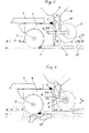
- FIGs. 5 and 6 of the accompanying drawings schematically represent an embodiment of the object of the invention.
- Fig. 5 shows in principle how the constituent parts of the new burrow builder are assembled; the frame 1 and the coulter 4, with recessed splitting disc 3, are rigidly linked together, as is the mole rocket 5 at the base of the coulter.
- the arm or frame 6, carrying the compacting-driving wheel as well as the distribution device toxic bait 8, 9, 10, is attached to the coulter by a double bond.
- the front part of the frame is fixed to the coulter by an articulation A; another point F, located behind this articulation A on the frame, is connected by a variable-length element 23 to another point C of the coulter or frame situated above the articulation A.
- the ACF connection system determines a variable triangle.
- the variable CF side of the ACF triangle constitutes the essential part of this attachment system: it is a compensating device which has a suspension-compression function of the frame carrying the compacting-driving wheel 7.
- Fig. 5 shows the relation to the ground of the burrow builder under normal working conditions, that is to say when the mole rocket is at the maximum desired depth, the latter being also determined by the maximum high position of the compacting wheel- coach (arm or frame 6 in horizontal position); this position corresponds to that which the conventional burrow builder would have.
- Fig. 6 shows the relation to the ground of the compensator burrow builder in conditions of obstacles on the ground, preventing the mole rocket from following its normal depth line.
- the disc 3 and the mole rocket push the coulter and all that is fixedly attached to it up; thanks to the articulation A and the function of the compensator CF, the compacting-driving wheel is pushed down, presses the earth above the tail of the rocket-mole, forms the roof of the gallery and continues to drive the distributor of toxic granules or baits.
- the arm 6 connecting the articulation A and the axis of the compacting wheel determines in this low position of the wheel, relative to the position it would have in rigid system (drawn in dotted lines), an angle ⁇ .
- This angle varies constantly during the work of the burrow builder depending on the soil; when it is maximum, the burrow builder is at the limit of elevation by obstacles from the ground beyond which it is no longer possible to make a satisfactory artificial gallery, the contact of the tamping wheel with the ground being interrupted as well as the distribution of toxic baits.
- An adjustment device makes it possible to correct the pressure exerted from the fixed point of the coulter C on the mobile point F of the frame of the compacting wheel.
- the compensator can be a simple mechanical element with variable tension or a hydropneumatic element with adjustable pressure.
- a tilting system can be adopted, the compensator then being placed in front of the articulation A, above or in the extension of the wheel-carrying arm.
- the solution shown in fig. 5 is however the simplest to build.
- the attachment system may possibly be non-adjustable.
Abstract
Description
Dispositif pour créer dans le sol une galerie tout en y introduisant des appâts toxiques pour combattre les rongeurs souterrainsDevice for creating a gallery in the ground while introducing toxic baits to combat underground rodents
Un burrow builder ou "faiseur de galeries dans le sol" est une machine agricole, attelée à un tracteur, qui permet de tracer dans le sol des prairies un sillon recouvert ou galerie artificielle, laquelle traverse le réseau de galeries naturelles construites par les rongeurs souterrains (par exemple le campagnol terrestre). Elle permet de déposer sur le plancher de la galerie artificielle des appâts toxiques sous forme de granulés pour lutter contre les rongeurs terricoles.A burrow builder or "maker of galleries in the ground" is an agricultural machine, coupled to a tractor, which makes it possible to trace in the soil of the meadows a covered furrow or artificial gallery, which crosses the network of natural galleries built by the underground rodents (for example the ground vole). It allows toxic bait in the form of granules to be deposited on the floor of the artificial gallery to fight against ground rodents.
Les fig. 1 à 4 des dessins ci-joints se rapportent au type de machine connu.Figs. 1 to 4 of the attached drawings relate to the type of machine known.
Cette machine comprend en général trois parties distinctes (voir fig. 1):
- 1) le
bâti 1 portant undisque fendeur 3 - 2) le
coutre 4 avec à sa base un tube profilé ou "fusée-taupe" 5 - 3) le dispositif de
distribution
- 1) the
frame 1 carrying a splittingdisc 3 - 2) coulter 4 with a profiled tube or "rocket-mole" at its
base 5 - 3) the
distribution device toxic baits 13 associated with a compacting-driving wheel 7
Dans les burrow builder conventionnels construits à ce jour, attelés au tracteur par l'intermédiaire du dispositif d'attache à trois points 2, les trois parties indiquées ci-dessus sont solidaires entre elles de manière fixe et rigide; seul le disque fendeur 3 est monté sur un axe vertical permettant l'oscillation latérale du disque. Le coutre 4 porte à sa partie arrière une ligne verticale de trous 11 permettant de fixer à différents niveaux la roue arrière tasseuse-entraîneuse 7, déterminant par là la profondeur fixe du travail de la machineo Derrière le coutre se trouve un tube profilé 12 conduisant les appâts toxiques depuis le distributeur 9, entraîné par la chaîne 10, jusqu'à la partie creuse de la fusée-taupe 5, ces appâts tombant sur le plancher de la galerie artificielle 14. La fig. 2 montre le résultat du passage de la fusée-taupe et la jonction de cette galerie 14 avec une galerie naturelle 16. 15 indique le toit de la galerie 14 fermé par la roue 7. La fig. 3 montre en coupe la fusée-taupe 5 solidaire du coutre 4.In the conventional burrow builder built to date, coupled to the tractor via the three-
Cette machine permet de traiter sélectivement les prairies envahies de rongeurs sans pour autant exposer d'autres habitants du biotope (en particulier les oiseaux) à des toxiques qui ne leur sont pas destinés.This machine makes it possible to selectively treat meadows invaded by rodents without exposing other inhabitants of the biotope (in particular birds) to poisons which are not intended for them.
Les burrow builder conventionnels travaillent correctement lorsque le sol, à la profondeur de passage de la fusée-taupe, ne contient pas d'obstacles (fig. 1), telles que grosses pierres, voire encore de la roche affleurante. Cette profondeur se situe généralement entre 13 et 15 cm en dessous de la surface. Cette condition de sol n'est que rarement réalisée dans les terres de prairies du Jura et des Préalpes, comme en général dans les reliefs montagneux; elle l'est plus facilement dans les zones de terres labourées régulièrement (terres assolées), soit en condition de plaine. Les burrow builder conventionnels sont mal adaptés aux conditions très changeantes des prairies d'altitude. Les obstacles grossiers 17 présents à la profondeur normale de travail de la fusée-taupe et du disque fendeur (fig. 4) soulèvent le burrow builder et condamnent la fonction de la roue tasseuse-entraîneuse 7. Il en résulte que la galerie artificielle est mal fermée, que les appâts toxiques ne sont plus distribués, que le traitement n'est dès lors que partiel et que son efficacité devient insuffisante. Les figo 1 et 4 donnent l'explication de ces défauts de comportement au sol des burrow builder conventionnels; à cause des obstacles dans le sol, la fusée-taupe ne décrit pas dans l'espace une ligne parallèle à la surface du sol, mais une ligne sinusoïdale; l'amplitude de cette sinusoïdale est transmise à tous les éléments reliés de manière fixe au coutre, ce qui détermine en particulier pour la roue tasseuse-entratneuse la perte de contact avec le sol.Conventional burrow builder works well when the ground, at the depth of passage of the rocket-mole, does not contain obstacles (fig. 1), such as large stones, or even flush rock. This depth is generally between 13 and 15 cm below the surface. This soil condition is only rarely achieved in the prairie lands of the Jura and Pre-Alps, as in general in mountainous reliefs; it is easier to do so in areas of land regularly plowed (land in rotation), ie in plain conditions. Conventional burrow builder is ill-suited to the very changing conditions of mountain meadows. The
Dans cette condition de travail, le burrow builder laboure et maltraite le gazon, mais ne traite pas la prairie au sens propre du travail. La mauvaise qualité du traitement tient au fait que les terriers ou systèmes d'habitation des rongeurs visés ne sont pas ou que peu pourvus en appâts toxiques.In this working condition, the burrow builder plows and mistreats the lawn, but does not treat the meadow in the proper sense of the job. The poor quality of the treatment is due to the fact that the burrows or housing systems of the rodents concerned are not or only slightly provided with toxic bait.
En analysant le comportement des burrow builder conventionnels dans les différentes conditions du sol, on a constaté que les variations d'amplitude de la sinusoïdale tracée par la fusée-taupe ne déterminent pas dans tous les cas l'incapacité de fabriquer une galerie artificielle satisfaisante; c'est le système d'attache rigide de la roue tasseuse-entratneuse, au coutre, qui détermine la perte de contact avec le sol de cette roue, d'ou l'absence de fermeture du sillon et l'absence de dépôt des appâts toxiques. D'où aussi cette galerie de traitement discontinue.By analyzing the behavior of conventional burrow builder in the different soil conditions, it was found that the variations in amplitude of the sinusoidal traced by the rocket-mole do not in all cases determine the inability to build a satisfactory artificial gallery; it is the rigid attachment system of the packer-driving wheel, with coulter, which determines the loss of contact with the ground of this wheel, hence the absence of closing of the furrow and the absence of bait deposition toxic. Hence also this discontinuous processing gallery.
La présente invention concerne un dispositif pour créer des galeries dans le sol en y introduisant des appâts toxiques, qui ne présente pas les inconvénients des burrow builder actuels et cela grâce à l'attache articulée du dispositif liant la roue tasseuse au coutre. Bien que travaillant, dans le principe général, comme les burrow builder conventionnels rigides, ce nouveau type s'en distingue par une particularité essentielle quant à la qualité du travail obtenu, résultant d'une meilleure adaptation aux différentes conditions du sol.The present invention relates to a device for creating galleries in the ground by introducing toxic baits, which does not have the drawbacks of current burrow builder and this thanks to the articulated attachment of the device linking the tamping wheel to the coulter. Although working, in general, like rigid conventional burrow builder, this new type is distinguished by an essential peculiarity as to the quality of the work obtained, resulting from a better adaptation to different soil conditions.
Les fig. 5 et 6 des dessins annexés représentent schématiquement une forme d'exécution de l'objet de l'invention.Figs. 5 and 6 of the accompanying drawings schematically represent an embodiment of the object of the invention.
La fige 5 montre dans le principe la manière dont sont assemblées les parties constituantes du nouveau burrow builder; le bâti 1 et le coutre 4, à disque fendeur encastré 3, sont liés entre eux de manière rigide, de même que la fusée-taupe 5 à la base du coutre. Par contre, le bras ou cadre 6, portant la roue tasseuse-entraîneuse ainsi que le dispositif de distribution des appâts toxiques 8, 9, 10, est rattaché au coutre par une double liaison. La partie avant du cadre est fixée au coutre par une articulation A; un autre point F, situé en arrière de cette articulation A sur le cadre, est relié par un élément à longueur variable 23 à un autre point C du coutre ou bâti situé en dessus de l'articulation A. Le système de liaison ACF détermine un triangle variable. Le côté CF, variable, du triangle ACF constitue la partie essentielle de ce système d'attache: c'est un dispositif compensateur qui a une fonction de suspension-compression du cadre portant la roue tasseuse-entratneuse 7.Fig. 5 shows in principle how the constituent parts of the new burrow builder are assembled; the
La fig. 5 montre la relation au sol du burrow builder dans les conditions normales de travail, c'est-à-dire lorsque la fusée-taupe est à la profondeur maximale désirée, cette dernière étant aussi déterminée par la position haute maximale de la roue tasseuse-entraîneuse (bras ou cadre 6 en position horizontale); cette position correspond à celle qu'aurait le burrow builder conventionnel. La fig. 6 montre la relation au sol du burrow builder à compensateur en condition d'obstacles au sol, empêchant la fusée-taupe à suivre sa ligne de profondeur normale. En s'élevant au-dessus de l'obstacle 17 dans le sol, le disque 3 et la fusée-taupe poussent le coutre et tout ce qui lui est rattaché de manière fixe vers le haut; grâce à l'articulation A et à la fonction du compensateur CF, la roue tasseuse-entraîneuse est poussée vers le bas, presse la terre en dessus de la queue de la fusée-taupe, forme le toit de la galerie et continue d'entraîner le distributeur de granulés ou appâts toxiques. Le bras 6 liant l'articulation A et l'axe de la roue tasseuse détermine dans cette position basse de la roue, par rapport à la position qu'il aurait en système rigide (dessinée en pointillé), un angle α. Cet angle varie constamment lors du travail du burrow builder en fonction du sol; lorsqu'il est maximum, le burrow builder est à la limite d'élévation par les obstacles du sol au-delà de laquelle il n'est plus possible de fabriquer une galerie artificielle satisfaisante, le contact de la roue tasseuse avec le sol étant interrompu ainsi que la distribution des appâts toxiques.Fig. 5 shows the relation to the ground of the burrow builder under normal working conditions, that is to say when the mole rocket is at the maximum desired depth, the latter being also determined by the maximum high position of the compacting wheel- coach (arm or
Cet arrêt de fonction du burrow builder intervient très tôt chez les burrow builder conventionnels. Dans le burrow builder à compensateur, cette situation ne se produit que lorsque l'angle α devient trop grand. Toutes les situations déterminant un angle α compris entre les valeurs α = O et α maximum sont maitrisées par le système compensateur. Cela permet de tracer une galerie artificielle continue, dans des conditions non extrêmes de sol, là où les burrow builder conventionnels ne traceraient déjà plus que des segments de galeries artificielles (galeries continues). Une particularité du système de compensation est de permettre la valeur limite de l'angle α ; on peut donc changer les degrés de liberté de la roue tasseuse, c'est-à-dire régler l'ampleur d'oscillation verticale de cette roue à l'intérieur de laquelle la galerie artificielle sera fabriquée de manière continue.This cessation of function of the burrow builder occurs very early in conventional burrow builder. In the compensator burrow builder, this situation only occurs when the angle α becomes too large. All the situations determining an angle α comprised between the values α = O and α maximum are mastered by the compensating system. This makes it possible to draw a continuous artificial gallery, in non-extreme soil conditions, where conventional burrow builder would already draw only segments of artificial galleries (continuous galleries). A special feature of the compensation system is that it allows the limit value of the angle α; it is therefore possible to change the degrees of freedom of the compacting wheel, that is to say to adjust the extent of vertical oscillation of this wheel inside which the artificial gallery will be manufactured continuously.
La dureté et la résistance du sol variant en fonction de sa constitution et son degré d'humidité, cela constitue un facteur de variation important du travail du compensateur; il importe que le compensateur exerce une force variable et réglable. Un dispositif de réglage permet de corriger la pression exercée depuis le point fixe du coutre C sur le point mobile F du cadre de la roue tasseuse. Le compensateur peut être un élément mécanique simple à tension variable ou encore un élément hydropneumatique à pression réglable.The hardness and resistance of the soil varying according to its constitution and its degree of humidity, this constitutes an important factor of variation in the work of the compensator; it is important that the compensator exerts a variable and adjustable force. An adjustment device makes it possible to correct the pressure exerted from the fixed point of the coulter C on the mobile point F of the frame of the compacting wheel. The compensator can be a simple mechanical element with variable tension or a hydropneumatic element with adjustable pressure.
Au lieu du système d'attache montré par la fig. 5, on peut adopter un système a bascule, le compensateur étant alors placé en avant de l'articulation A, au-dessus ou dans le prolongement du bras porte-roue. La solution démontrée par la fig. 5 est cependant la plus simple à construire. Le système d'attache peut éventuellement être non réglable.Instead of the fastening system shown in fig. 5, a tilting system can be adopted, the compensator then being placed in front of the articulation A, above or in the extension of the wheel-carrying arm. The solution shown in fig. 5 is however the simplest to build. The attachment system may possibly be non-adjustable.
Claims (5)
Priority Applications (1)
| Application Number | Priority Date | Filing Date | Title |
|---|---|---|---|
| AT80810015T ATE1164T1 (en) | 1979-03-28 | 1980-01-21 | DEVICE FOR GAIT SHAPING AND TOXIC INJECTION IN TERMINAL RODENT COMBAT. |
Applications Claiming Priority (2)
| Application Number | Priority Date | Filing Date | Title |
|---|---|---|---|
| CH2855/79 | 1979-03-28 | ||
| CH285579A CH627341A5 (en) | 1979-03-28 | 1979-03-28 | DEVICE FOR CREATING A GALLERY IN THE GROUND WHILE INSERTING TOXIC BAITS TO COMBAT UNDERGROUND RODENTS. |
Publications (2)
| Publication Number | Publication Date |
|---|---|
| EP0018314A1 true EP0018314A1 (en) | 1980-10-29 |
| EP0018314B1 EP0018314B1 (en) | 1982-06-09 |
Family
ID=4243090
Family Applications (1)
| Application Number | Title | Priority Date | Filing Date |
|---|---|---|---|
| EP80810015A Expired EP0018314B1 (en) | 1979-03-28 | 1980-01-21 | Tunnel forming and poison depositing device for exterminating subsoil rodents |
Country Status (4)
| Country | Link |
|---|---|
| EP (1) | EP0018314B1 (en) |
| AT (1) | ATE1164T1 (en) |
| CH (1) | CH627341A5 (en) |
| DE (1) | DE3060507D1 (en) |
Cited By (5)
| Publication number | Priority date | Publication date | Assignee | Title |
|---|---|---|---|---|
| AT381834B (en) * | 1984-05-07 | 1986-12-10 | Franz Kaiser Fa | DEVICE FOR FIGHTING UNDERBODY PLANTS IN AGRICULTURAL PEST |
| FR2619670A1 (en) * | 1987-08-25 | 1989-03-03 | Delos Ets | Device for injecting into the ground fluid or material in a divided form, particularly liquid or gaseous fertiliser |
| FR2644674A1 (en) * | 1989-03-23 | 1990-09-28 | Xaintois Equipement Agricole | Towed device making it possible to form a tunnel in the ground and to insert a product therein |
| FR2799612A1 (en) * | 1999-10-19 | 2001-04-20 | Sarl Decouzon | Soil fumigation machine which diffuses inter-reactive substances into soil has two reservoirs for reactants each fitted with feed pipes and pumps which feed reactants to a single dispensing tube mounted on plow blade |
| CZ308858B6 (en) * | 2020-06-24 | 2021-07-14 | Výzkumný ústav rostlinné výroby v.v.i. | Equipment for laying rodent bait in the soil |
Families Citing this family (1)
| Publication number | Priority date | Publication date | Assignee | Title |
|---|---|---|---|---|
| DE29722383U1 (en) * | 1997-12-18 | 1998-04-09 | Huelso Hans | Sauerkerr |
Citations (3)
| Publication number | Priority date | Publication date | Assignee | Title |
|---|---|---|---|---|
| DE6900899U (en) * | 1968-01-12 | 1969-04-30 | Mechanox N V | DEVICE FOR INTRODUCING MEANS FOR IMPROVING SOIL QUALITY INTO THE SOIL |
| DE7420796U (en) * | 1974-11-07 | Chemische Fabrik Wuelfel Just & Dittmar | Mobile device for introducing granular material into the ground | |
| DE2752646A1 (en) * | 1977-11-25 | 1979-06-07 | Bertram Henry Norbury | DEVICE FOR LIFTING THE GROUND WITHOUT TURNING |
-
1979
- 1979-03-28 CH CH285579A patent/CH627341A5/en not_active IP Right Cessation
-
1980
- 1980-01-21 EP EP80810015A patent/EP0018314B1/en not_active Expired
- 1980-01-21 DE DE8080810015T patent/DE3060507D1/en not_active Expired
- 1980-01-21 AT AT80810015T patent/ATE1164T1/en not_active IP Right Cessation
Patent Citations (3)
| Publication number | Priority date | Publication date | Assignee | Title |
|---|---|---|---|---|
| DE7420796U (en) * | 1974-11-07 | Chemische Fabrik Wuelfel Just & Dittmar | Mobile device for introducing granular material into the ground | |
| DE6900899U (en) * | 1968-01-12 | 1969-04-30 | Mechanox N V | DEVICE FOR INTRODUCING MEANS FOR IMPROVING SOIL QUALITY INTO THE SOIL |
| DE2752646A1 (en) * | 1977-11-25 | 1979-06-07 | Bertram Henry Norbury | DEVICE FOR LIFTING THE GROUND WITHOUT TURNING |
Cited By (7)
| Publication number | Priority date | Publication date | Assignee | Title |
|---|---|---|---|---|
| AT381834B (en) * | 1984-05-07 | 1986-12-10 | Franz Kaiser Fa | DEVICE FOR FIGHTING UNDERBODY PLANTS IN AGRICULTURAL PEST |
| FR2619670A1 (en) * | 1987-08-25 | 1989-03-03 | Delos Ets | Device for injecting into the ground fluid or material in a divided form, particularly liquid or gaseous fertiliser |
| FR2644674A1 (en) * | 1989-03-23 | 1990-09-28 | Xaintois Equipement Agricole | Towed device making it possible to form a tunnel in the ground and to insert a product therein |
| FR2799612A1 (en) * | 1999-10-19 | 2001-04-20 | Sarl Decouzon | Soil fumigation machine which diffuses inter-reactive substances into soil has two reservoirs for reactants each fitted with feed pipes and pumps which feed reactants to a single dispensing tube mounted on plow blade |
| WO2001028323A1 (en) * | 1999-10-19 | 2001-04-26 | Calliope | Device for diffusing in the soil volatile treating products |
| US6698367B1 (en) | 1999-10-19 | 2004-03-02 | Calliope | Device for diffusing in the soil volatile treating products |
| CZ308858B6 (en) * | 2020-06-24 | 2021-07-14 | Výzkumný ústav rostlinné výroby v.v.i. | Equipment for laying rodent bait in the soil |
Also Published As
| Publication number | Publication date |
|---|---|
| EP0018314B1 (en) | 1982-06-09 |
| ATE1164T1 (en) | 1982-06-15 |
| DE3060507D1 (en) | 1982-07-29 |
| CH627341A5 (en) | 1982-01-15 |
Similar Documents
| Publication | Publication Date | Title |
|---|---|---|
| US5443023A (en) | Seed furrow closing apparatus for agricultural planters | |
| US4762075A (en) | Seed/fertilizer minimum tillage planter | |
| US4187916A (en) | Soil conditioning and seed bed preparing apparatus | |
| US4090456A (en) | Furrow opener and apparatus for no-tillage transplanters and planters | |
| EP1345487B1 (en) | Precision disc tiller with incorporated sowing elements | |
| US4244306A (en) | Minimum tillage planter | |
| US20020078869A1 (en) | Apparatus and method for clearing trash from furrow opener path | |
| US2713836A (en) | Apparatus for depth placement of seeds and fertilizer | |
| FR2461437A1 (en) | MECHANICAL MACHINE WITH DISC SOCKETS | |
| EP0052641A1 (en) | Furrow forming apparatus for a seed planter. | |
| US4345531A (en) | Apparatus and method for cultivating land | |
| US6095065A (en) | Apparatus for high speed application of liquid or dry fertilizer | |
| EP1976367B2 (en) | Machine for working the soil, such as a disc tiller | |
| USRE25237E (en) | Mulcher | |
| EP0018314B1 (en) | Tunnel forming and poison depositing device for exterminating subsoil rodents | |
| US5461994A (en) | Seed drill planting assembly | |
| EP0117745A1 (en) | Coulter seeder apparatus | |
| AU2004226690B2 (en) | Improved seed drill | |
| US4964351A (en) | Dry soil spreader for disk furrow opener | |
| CA2298395A1 (en) | Quick set variable scraper pressure coulter assembly | |
| EP0127549B1 (en) | Method of constructing sports grounds, and apparatus for carrrying out this method | |
| US11375657B2 (en) | Furrow cutting and press wheel assembly with adjacent seeding unit | |
| FR2866195A1 (en) | Agrarian vehicle for entry of e.g. seed, has blade loosening soil by slicing and lifting soil without returning cut slice, and driver seat permitting supervision of work performed by disk and blade | |
| EP0342065B1 (en) | Implement for treating ploughed land | |
| US4860672A (en) | Trip mechanism for drill seed boot |
Legal Events
| Date | Code | Title | Description |
|---|---|---|---|
| PUAI | Public reference made under article 153(3) epc to a published international application that has entered the european phase |
Free format text: ORIGINAL CODE: 0009012 |
|
| AK | Designated contracting states |
Designated state(s): AT BE DE FR GB IT LU NL SE |
|
| 17P | Request for examination filed |
Effective date: 19801106 |
|
| ITF | It: translation for a ep patent filed |
Owner name: ORGANIZZAZIONE D'AGOSTINI |
|
| GRAA | (expected) grant |
Free format text: ORIGINAL CODE: 0009210 |
|
| AK | Designated contracting states |
Designated state(s): AT BE DE FR GB IT LU NL SE |
|
| REF | Corresponds to: |
Ref document number: 1164 Country of ref document: AT Date of ref document: 19820615 Kind code of ref document: T |
|
| REF | Corresponds to: |
Ref document number: 3060507 Country of ref document: DE Date of ref document: 19820729 |
|
| PG25 | Lapsed in a contracting state [announced via postgrant information from national office to epo] |
Ref country code: LU Free format text: LAPSE BECAUSE OF NON-PAYMENT OF DUE FEES Effective date: 19830131 |
|
| PGFP | Annual fee paid to national office [announced via postgrant information from national office to epo] |
Ref country code: LU Payment date: 19831207 Year of fee payment: 5 |
|
| PGFP | Annual fee paid to national office [announced via postgrant information from national office to epo] |
Ref country code: AT Payment date: 19841227 Year of fee payment: 6 |
|
| PGFP | Annual fee paid to national office [announced via postgrant information from national office to epo] |
Ref country code: FR Payment date: 19841228 Year of fee payment: 6 |
|
| PGFP | Annual fee paid to national office [announced via postgrant information from national office to epo] |
Ref country code: SE Payment date: 19841231 Year of fee payment: 6 Ref country code: BE Payment date: 19841231 Year of fee payment: 6 |
|
| PGFP | Annual fee paid to national office [announced via postgrant information from national office to epo] |
Ref country code: NL Payment date: 19850131 Year of fee payment: 6 |
|
| PGFP | Annual fee paid to national office [announced via postgrant information from national office to epo] |
Ref country code: DE Payment date: 19850308 Year of fee payment: 6 |
|
| PG25 | Lapsed in a contracting state [announced via postgrant information from national office to epo] |
Ref country code: AT Effective date: 19860121 |
|
| PG25 | Lapsed in a contracting state [announced via postgrant information from national office to epo] |
Ref country code: SE Effective date: 19860122 |
|
| PG25 | Lapsed in a contracting state [announced via postgrant information from national office to epo] |
Ref country code: BE Effective date: 19860131 |
|
| BERE | Be: lapsed |
Owner name: SOC CANTONALE NEUCHATELOISE D'AGRICULTURE ET DE V Effective date: 19860131 |
|
| PG25 | Lapsed in a contracting state [announced via postgrant information from national office to epo] |
Ref country code: NL Effective date: 19860801 |
|
| GBPC | Gb: european patent ceased through non-payment of renewal fee | ||
| NLV4 | Nl: lapsed or anulled due to non-payment of the annual fee | ||
| PG25 | Lapsed in a contracting state [announced via postgrant information from national office to epo] |
Ref country code: FR Free format text: LAPSE BECAUSE OF NON-PAYMENT OF DUE FEES Effective date: 19860930 |
|
| PG25 | Lapsed in a contracting state [announced via postgrant information from national office to epo] |
Ref country code: DE Effective date: 19861001 |
|
| REG | Reference to a national code |
Ref country code: FR Ref legal event code: ST |
|
| PG25 | Lapsed in a contracting state [announced via postgrant information from national office to epo] |
Ref country code: GB Effective date: 19881118 |
|
| EUG | Se: european patent has lapsed |
Ref document number: 80810015.0 Effective date: 19861023 |
|
| PLBE | No opposition filed within time limit |
Free format text: ORIGINAL CODE: 0009261 |
|
| STAA | Information on the status of an ep patent application or granted ep patent |
Free format text: STATUS: NO OPPOSITION FILED WITHIN TIME LIMIT |