EP0018290B1 - Procédé de contrôle de crayons combustibles destinés à des assemblages pour réacteur nucléaire et dispositif correspondant - Google Patents
Procédé de contrôle de crayons combustibles destinés à des assemblages pour réacteur nucléaire et dispositif correspondant Download PDFInfo
- Publication number
- EP0018290B1 EP0018290B1 EP80400526A EP80400526A EP0018290B1 EP 0018290 B1 EP0018290 B1 EP 0018290B1 EP 80400526 A EP80400526 A EP 80400526A EP 80400526 A EP80400526 A EP 80400526A EP 0018290 B1 EP0018290 B1 EP 0018290B1
- Authority
- EP
- European Patent Office
- Prior art keywords
- waves
- fuel rod
- tube
- fuel
- sheath
- Prior art date
- Legal status (The legal status is an assumption and is not a legal conclusion. Google has not performed a legal analysis and makes no representation as to the accuracy of the status listed.)
- Expired
Links
- 239000000446 fuel Substances 0.000 title claims description 76
- 238000000034 method Methods 0.000 title claims description 36
- 230000000712 assembly Effects 0.000 title claims description 10
- 238000000429 assembly Methods 0.000 title claims description 10
- 235000019687 Lamb Nutrition 0.000 claims description 21
- XLYOFNOQVPJJNP-UHFFFAOYSA-N water Substances O XLYOFNOQVPJJNP-UHFFFAOYSA-N 0.000 claims description 18
- 239000000463 material Substances 0.000 claims description 9
- 238000004519 manufacturing process Methods 0.000 claims description 7
- 230000005540 biological transmission Effects 0.000 claims description 5
- 238000006073 displacement reaction Methods 0.000 claims 1
- 244000045947 parasite Species 0.000 claims 1
- 238000005253 cladding Methods 0.000 description 34
- 238000002604 ultrasonography Methods 0.000 description 12
- 230000007547 defect Effects 0.000 description 9
- 230000002950 deficient Effects 0.000 description 9
- 229920005372 Plexiglas® Polymers 0.000 description 8
- 239000004926 polymethyl methacrylate Substances 0.000 description 7
- 238000005259 measurement Methods 0.000 description 6
- 238000001514 detection method Methods 0.000 description 4
- 230000003071 parasitic effect Effects 0.000 description 3
- 238000003466 welding Methods 0.000 description 3
- 230000000052 comparative effect Effects 0.000 description 2
- 239000007789 gas Substances 0.000 description 2
- 239000001307 helium Substances 0.000 description 2
- 229910052734 helium Inorganic materials 0.000 description 2
- SWQJXJOGLNCZEY-UHFFFAOYSA-N helium atom Chemical compound [He] SWQJXJOGLNCZEY-UHFFFAOYSA-N 0.000 description 2
- 239000002184 metal Substances 0.000 description 2
- 239000003758 nuclear fuel Substances 0.000 description 2
- 239000008188 pellet Substances 0.000 description 2
- 230000001902 propagating effect Effects 0.000 description 2
- 230000002285 radioactive effect Effects 0.000 description 2
- 238000007789 sealing Methods 0.000 description 2
- 230000035945 sensitivity Effects 0.000 description 2
- VVQNEPGJFQJSBK-UHFFFAOYSA-N Methyl methacrylate Chemical compound COC(=O)C(C)=C VVQNEPGJFQJSBK-UHFFFAOYSA-N 0.000 description 1
- 230000002159 abnormal effect Effects 0.000 description 1
- 230000002238 attenuated effect Effects 0.000 description 1
- 230000015572 biosynthetic process Effects 0.000 description 1
- 238000006243 chemical reaction Methods 0.000 description 1
- 238000009833 condensation Methods 0.000 description 1
- 230000005494 condensation Effects 0.000 description 1
- 239000002826 coolant Substances 0.000 description 1
- 239000000498 cooling water Substances 0.000 description 1
- 230000008878 coupling Effects 0.000 description 1
- 238000010168 coupling process Methods 0.000 description 1
- 238000005859 coupling reaction Methods 0.000 description 1
- 239000011261 inert gas Substances 0.000 description 1
- 238000012986 modification Methods 0.000 description 1
- 230000004048 modification Effects 0.000 description 1
- 235000010603 pastilles Nutrition 0.000 description 1
- 229910000679 solder Inorganic materials 0.000 description 1
Images
Classifications
-
- G—PHYSICS
- G21—NUCLEAR PHYSICS; NUCLEAR ENGINEERING
- G21C—NUCLEAR REACTORS
- G21C17/00—Monitoring; Testing ; Maintaining
- G21C17/06—Devices or arrangements for monitoring or testing fuel or fuel elements outside the reactor core, e.g. for burn-up, for contamination
-
- G—PHYSICS
- G01—MEASURING; TESTING
- G01N—INVESTIGATING OR ANALYSING MATERIALS BY DETERMINING THEIR CHEMICAL OR PHYSICAL PROPERTIES
- G01N29/00—Investigating or analysing materials by the use of ultrasonic, sonic or infrasonic waves; Visualisation of the interior of objects by transmitting ultrasonic or sonic waves through the object
- G01N29/04—Analysing solids
- G01N29/041—Analysing solids on the surface of the material, e.g. using Lamb, Rayleigh or shear waves
-
- G—PHYSICS
- G01—MEASURING; TESTING
- G01N—INVESTIGATING OR ANALYSING MATERIALS BY DETERMINING THEIR CHEMICAL OR PHYSICAL PROPERTIES
- G01N29/00—Investigating or analysing materials by the use of ultrasonic, sonic or infrasonic waves; Visualisation of the interior of objects by transmitting ultrasonic or sonic waves through the object
- G01N29/34—Generating the ultrasonic, sonic or infrasonic waves, e.g. electronic circuits specially adapted therefor
- G01N29/348—Generating the ultrasonic, sonic or infrasonic waves, e.g. electronic circuits specially adapted therefor with frequency characteristics, e.g. single frequency signals, chirp signals
-
- G—PHYSICS
- G01—MEASURING; TESTING
- G01N—INVESTIGATING OR ANALYSING MATERIALS BY DETERMINING THEIR CHEMICAL OR PHYSICAL PROPERTIES
- G01N2291/00—Indexing codes associated with group G01N29/00
- G01N2291/02—Indexing codes associated with the analysed material
- G01N2291/028—Material parameters
- G01N2291/02845—Humidity, wetness
-
- G—PHYSICS
- G01—MEASURING; TESTING
- G01N—INVESTIGATING OR ANALYSING MATERIALS BY DETERMINING THEIR CHEMICAL OR PHYSICAL PROPERTIES
- G01N2291/00—Indexing codes associated with group G01N29/00
- G01N2291/04—Wave modes and trajectories
- G01N2291/042—Wave modes
- G01N2291/0427—Flexural waves, plate waves, e.g. Lamb waves, tuning fork, cantilever
-
- G—PHYSICS
- G01—MEASURING; TESTING
- G01N—INVESTIGATING OR ANALYSING MATERIALS BY DETERMINING THEIR CHEMICAL OR PHYSICAL PROPERTIES
- G01N2291/00—Indexing codes associated with group G01N29/00
- G01N2291/10—Number of transducers
- G01N2291/102—Number of transducers one emitter, one receiver
-
- Y—GENERAL TAGGING OF NEW TECHNOLOGICAL DEVELOPMENTS; GENERAL TAGGING OF CROSS-SECTIONAL TECHNOLOGIES SPANNING OVER SEVERAL SECTIONS OF THE IPC; TECHNICAL SUBJECTS COVERED BY FORMER USPC CROSS-REFERENCE ART COLLECTIONS [XRACs] AND DIGESTS
- Y02—TECHNOLOGIES OR APPLICATIONS FOR MITIGATION OR ADAPTATION AGAINST CLIMATE CHANGE
- Y02E—REDUCTION OF GREENHOUSE GAS [GHG] EMISSIONS, RELATED TO ENERGY GENERATION, TRANSMISSION OR DISTRIBUTION
- Y02E30/00—Energy generation of nuclear origin
- Y02E30/30—Nuclear fission reactors
Definitions
- the invention relates to a method for checking fuel rods intended for assemblies for a nuclear reactor, obtained by introducing fuel into a tubular sheath, filling with a gas under pressure and sealing off this sheath, this process aiming to detect traces of moisture possibly introduced into the pencil during its manufacture.
- the invention also relates to a device for implementing this method of controlling fuel rods.
- fuel pellets are introduced into a metal tube called a cladding and this tube is closed at each of its ends by plugs tightly welded to the ends of the tube after having evacuated the air from inside the tube and introduced helium under sufficient pressure.
- the closed fuel rod therefore contains an inert gas under pressure which remains inside the cladding throughout the life of the fuel rod. This avoids the presence inside the fuel rod of aggressive materials with respect to nuclear fuel or cladding material or of materials liable to undergo nuclear reactions leading to the production of dangerous radioactive products.
- the fuel rods are assembled in the form of parallel bundles by means of connecting structures allowing the constitution of the assemblies which will be introduced into the core of the nuclear reactor. If moisture was introduced inside the fuel rod during its manufacture, the cladding of this rod is liable to be hydrided during the operation of the reactor.
- This control must be done from the outside of a fuel rod sealed and with very good sensitivity.
- the introduction of the cooling water inside the fuel rods also causes an attenuation of the extremely sensitive ultrasonic signal because of the relatively large amounts of water introduced into the fuel rod by the cracks in its cladding.
- the propagation of ultrasound in the sheath of the fuel element takes place from an accessible area of the fuel rod in the assembly, that is to say from the plug of this combustible element or from the area immediately adjacent to the plug.
- the rest of the fuel rod is not accessible on the assembly from which the end plates have been removed, except as regards the fuel rods disposed at the periphery of the assembly.
- the object of the invention is therefore to propose a method for controlling new fuel rods intended for assemblies for a nuclear reactor, obtained by introducing the fuel into a tubular sheath, filling with gas under pressure and sealing this sheath with plugs. tightly fixed to the sheath and constituting the ends of the fuel rod, to detect traces of moisture possibly introduced into the rod during its manufacture, this process having to allow the detection of extremely small amounts of humidity inside the rod and an exploration of the entire length of this fuel rod.
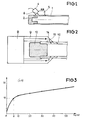
- ultrasonic waves are emitted in the cladding tube of the fuel element placed in the open air with an oblique incidence relative to the axis of the tube, from an area of the side wall of the tube, these waves producing, by reflection on the walls of the sheathing tube, waves of plates or Lamb waves; these Lamb waves are captured after a certain distance along the length of the cladding tube and the attenuation undergone by these Lamb waves is measured to deduce therefrom, by comparison with attenuation results obtained on another part of the length of the tube or on a standard tube, information on the possible presence of moisture in the fuel rod.
- the device for transmitting and receiving ultrasound comprises a transceiver 4 and a Plexiglas block 5 attached by its face 6 inclined by 45 ° relative to the axis of the fuel rod to the face of transmission and receiving the transducer 4.
- the Plexiglas wedge ensures good coupling between the transducer and the cladding tube 1 and for this has a cylindrical recess on its bearing face in contact with the cladding tube 1.
- the ultrasonic waves emitted by the transducer 4 are sent thanks to the Plexiglas wedge in the cladding tube 1 with an angle of incidence close to 45 ° relative to the axis of the tube.
- the preferential mode generally generated is the S o mode.
- the transducer 4 and the shim 5 are chosen so as to emit and to receive in a preferential way a mode of waves of Lamb which allows a propagation in the tube with weak attenuation and negligible parasitic signals in the case of a tube does not showing no defect and humidity.
- the ultrasonic transmitter and receiver device 8 is coupled to a connecting piece 9, the contact face 11 of which surrounds the external surface of the cladding tube 10 on its part close to the plug 12 .
- the ultrasonic waves reflected on the face 14 of the Plexiglas shim 9 are reflected towards the lateral surface of the tube 10 to penetrate this tube with an incidence close to 45 °.
- the waves reflected by the internal and external surfaces of the tube 10 give rise to Lamb waves propagating in the axial direction of the tube and do not undergo any reflection due to the plug 12 during their propagation towards the opposite end of the cladding tube .
- the transmitter-receiver device 4 or 8 makes it possible to collect the echo signal, to record this signal and to measure the attenuation due to the path in the tube.
- the attenuation is extremely low in all cases where the tube does not contain any moisture, except obviously the cases where accidentally the sheathing tube has a crack coming from a defect of manufacturing and where the solder between the cladding tube and the plug on which the reflection of the waves takes place is defective.
- the attenuation of the signal makes it possible to know the quantity of water being in the tube when a curve such as that shown in FIG. 3 has been drawn.
- a curve is obtained by carrying out attenuation measurements on standard cladding tubes containing metered quantities of water and plotting them on a graph as shown in FIG. 3.
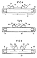
- the device 23, 25 is a device emitting ultrasonic waves and the device 24, 26 is a device receiving these waves after yp certain path of length 1 inside the tubular wall of the sheath 20.
- the distance 1 between the two transducers is obviously less than the length of the fuel rod so that it is possible to explore the entire surface of the fuel rod by moving the assembly of the emitter and the receiver separated by a length 1.
- the transmitter and the receiver of ultrasound can be made integral with the aid of a common frame which makes it possible to maintain the spacing 1 of these two transducers.
- the attenuation of the Lamb waves generated in the tube by the incident ultrasonic waves is measured with an angle close to 45 ° relative to l 'axis of the tube, between the transmitter and receiver of ultrasound.
- This device and this examination method are particularly advantageous when looking for defective pencils in order to draw them out and replace them. Indeed, the comparison of the results obtained on the different zones of the fuel rod is immediate and makes it possible to very quickly determine an anomaly on the sheath of the fuel rod.
- This method thus avoids the use of a preliminary calibration since it uses the direct comparison of the attenuations in the two parts of the cladding of the fuel rod in which the Lamb waves propagate simultaneously.
- this method has the advantage of eliminating the influence of the metallurgical or mechanical characteristics of the material constituting the sheath since the comparison is made on two parts of the same metal tube.
- the precise positioning of the sensors is ensured by observing the echo signals obtained for each of these two sensors and by moving these sensors so as to bring the echo signals into coincidence, which allows the comparison of the amplitudes.
- the waves emitted by the transceiver 33 will travel the path AB'BA '.
- Each of these paths represents a total path inside the identical cladding tube and includes reflections on the plugs 31 and 32, so that it is thus freed from disturbances due to possible heterogeneities of the tube material and to heterogeneities welds of the two plugs.
- the spurious signals due to this water are offset with respect to the echo signals on both recording.
- the echo signals are attenuated, which makes it possible, as before, to determine the amounts of water on the internal surface of the cladding tube. Obviously, two attenuation values are obtained which must be identical for both measurement channels.
- the method according to the invention makes it possible to detect and quantitatively determine very small traces of water inside a cladding tube of a new combustible rod by a measurement using propagation. ultrasonic waves in the side wall of the tube.
- the method according to the invention makes it possible to easily distinguish the physical defects of the fuel rod (cracks or welding defects in the plugs) from traces of humidity, by observing the signals picked up after a certain course in the wall of the tube.
- the method according to the invention obviously makes it possible also to eliminate the cladding tubes which have defects such as cracks or welding defects in the plugs.
- the frequency of the waves emitted can vary to a large extent, however the applicant's tests have shown that the optimal frequencies of these waves are less than 1 MHz.
- the method according to the invention and the corresponding devices are applicable not only in the case of fuel rods for assemblies intended to be placed in the core of nuclear pressurized water reactors but also to any type of fuel rods comprising a tube sheathing tightly closed with plugs.
- FIGS. 4 to 6 can advantageously be replaced by an annular sensor structure completely surrounding the tube, as shown in FIG. 2,
Landscapes
- Physics & Mathematics (AREA)
- General Physics & Mathematics (AREA)
- Pathology (AREA)
- Life Sciences & Earth Sciences (AREA)
- Chemical & Material Sciences (AREA)
- Analytical Chemistry (AREA)
- Biochemistry (AREA)
- Health & Medical Sciences (AREA)
- General Health & Medical Sciences (AREA)
- Immunology (AREA)
- Engineering & Computer Science (AREA)
- Acoustics & Sound (AREA)
- Plasma & Fusion (AREA)
- General Engineering & Computer Science (AREA)
- High Energy & Nuclear Physics (AREA)
- Investigating Or Analyzing Materials By The Use Of Ultrasonic Waves (AREA)
- Monitoring And Testing Of Nuclear Reactors (AREA)
Applications Claiming Priority (2)
| Application Number | Priority Date | Filing Date | Title |
|---|---|---|---|
| FR7909984 | 1979-04-20 | ||
| FR7909984A FR2454675A1 (fr) | 1979-04-20 | 1979-04-20 | Procede de controle de crayons combustibles destines a des assemblages pour reacteur nucleaire et dispositif correspondant |
Publications (2)
| Publication Number | Publication Date |
|---|---|
| EP0018290A1 EP0018290A1 (fr) | 1980-10-29 |
| EP0018290B1 true EP0018290B1 (fr) | 1982-11-03 |
Family
ID=9224527
Family Applications (1)
| Application Number | Title | Priority Date | Filing Date |
|---|---|---|---|
| EP80400526A Expired EP0018290B1 (fr) | 1979-04-20 | 1980-04-18 | Procédé de contrôle de crayons combustibles destinés à des assemblages pour réacteur nucléaire et dispositif correspondant |
Country Status (7)
| Country | Link |
|---|---|
| US (1) | US4366711A (cg-RX-API-DMAC10.html) |
| EP (1) | EP0018290B1 (cg-RX-API-DMAC10.html) |
| JP (1) | JPS56650A (cg-RX-API-DMAC10.html) |
| DE (1) | DE3061029D1 (cg-RX-API-DMAC10.html) |
| ES (1) | ES490687A0 (cg-RX-API-DMAC10.html) |
| FR (1) | FR2454675A1 (cg-RX-API-DMAC10.html) |
| ZA (1) | ZA802361B (cg-RX-API-DMAC10.html) |
Families Citing this family (18)
| Publication number | Priority date | Publication date | Assignee | Title |
|---|---|---|---|---|
| FR2493025B1 (fr) * | 1980-10-24 | 1986-04-18 | Framatome Sa | Procede et dispositif de detection d'elements combustibles defectueux dans un assemblage combustible pour reacteur nucleaire |
| DE3116978C2 (de) * | 1981-04-29 | 1986-06-12 | Brown Boveri Reaktor GmbH, 6800 Mannheim | Einrichtung zum Auffinden defekter Brennstabhüllrohre wassergekühlter Kernreaktoren |
| DE3149362C2 (de) * | 1981-12-12 | 1983-10-27 | Brown Boveri Reaktor GmbH, 6800 Mannheim | Verfahren zum Auffinden defekter Brennstabhüllrohre mit Hilfe von Ultraschall |
| GB2124764B (en) * | 1982-08-03 | 1986-01-08 | Atomic Energy Authority Uk | Ice detector |
| FR2538155B1 (fr) * | 1982-12-17 | 1988-08-12 | Fragema Framatome & Cogema | Procede et dispositif de detection d'elements combustibles defectueux utilisant l'absorption ultrasonore |
| FR2642560B1 (fr) * | 1989-01-30 | 1991-05-17 | Framatome Sa | Procede et dispositif de detection par ultrasons de crayons combustibles non etanches dans un assemblage combustible |
| US5790617A (en) * | 1992-03-26 | 1998-08-04 | Siemens Power Corporation | Method and apparatus for detection of failed fuel rods by use of acoustic energy frequency attenuation |
| EP0566862B1 (en) * | 1992-03-26 | 1995-08-02 | Siemens Power Corporation | Method and apparatus for detection of failed fuel rods by the use of acoustic energy wave attenuation |
| TW444205B (en) * | 1998-02-09 | 2001-07-01 | Siemens Power Corp | Method for the inspection of nuclear fuel rod for fretting and wear within a nuclear fuel assembly |
| EP0936630A1 (en) * | 1998-02-10 | 1999-08-18 | Siemens Power Corporation | Detection of nuclear fuel rod failure |
| US6923067B2 (en) | 1999-03-19 | 2005-08-02 | Betriebsforschungsinstitut Vdeh Institut Fur Angewandte Forschung Gmbh | Defect type classifying method |
| US20040206181A1 (en) * | 1999-03-22 | 2004-10-21 | Betriebsforschungsinstitut Vdeh Institut Fur Angewandte Forschung Gmbh | Defect type classifying method |
| KR101222012B1 (ko) * | 2011-07-08 | 2013-01-14 | 한전원자력연료 주식회사 | 핵연료집합체의 핵연료봉 외경 측정장치 |
| DE102014118623B3 (de) * | 2014-12-15 | 2016-04-28 | Areva Gmbh | Vorrichtung und Verfahren zur Durchführung einer Dichtheitsprüfung an Brennstabkapseln |
| US10234432B2 (en) * | 2016-08-04 | 2019-03-19 | The Boeing Company | Device and method to detect cracks in the countersink of a fastener |
| CN106770642A (zh) * | 2016-11-15 | 2017-05-31 | 中国科学院苏州生物医学工程技术研究所 | 水分测量装置和方法、兰姆波传感器及气体湿度测量方法 |
| CN106814135B (zh) * | 2017-01-26 | 2019-03-15 | 吉林大学 | 电弧塞焊接头的相控阵超声自动检测方法 |
| WO2021176545A1 (ja) * | 2020-03-03 | 2021-09-10 | 三菱電機株式会社 | 湿度センサ |
Family Cites Families (9)
| Publication number | Priority date | Publication date | Assignee | Title |
|---|---|---|---|---|
| US2912854A (en) * | 1955-05-27 | 1959-11-17 | Gen Motors Corp | Ultrasonic surface testing device |
| US3233449A (en) * | 1960-10-06 | 1966-02-08 | Republic Steel Corp | Method and apparatus for ultrasonic testing of pipe |
| US3512400A (en) * | 1967-04-13 | 1970-05-19 | Panametrics | Ultrasonic testing method |
| DE2642156A1 (de) * | 1976-09-20 | 1978-03-23 | Kraftwerk Union Ag | Verfahren und einrichtung zur auffindung defekter brennstaebe |
| DE2314650C3 (de) * | 1973-03-23 | 1978-10-12 | Kraftwerk Union Ag, 4330 Muelheim | Verfahren und Einrichtung zur Auffindung defekter Brennstäbe |
| DE2528422C3 (de) * | 1975-06-26 | 1979-06-13 | Babcock-Brown Boveri Reaktor Gmbh, 6800 Mannheim | Verfahren zum Lokalisieren undichter Hullrohre von Brennstäben eines Kernreaktor-Brennelementes und Vorrichtung zur Durchführung des Verfahrens |
| FR2325932A1 (fr) * | 1975-09-23 | 1977-04-22 | Tech Ind Mecanique Centre | Procede et dispositif d'examen superficiel par les ultra-sons |
| JPS5298893A (en) * | 1976-02-11 | 1977-08-19 | Westinghouse Electric Corp | Method of sensing and searching defective fuel element in reactor |
| DE2605962C2 (de) * | 1976-02-14 | 1982-05-06 | Brown Boveri Reaktor GmbH, 6800 Mannheim | Einrichtung zum Lokalisieren defekter Brennstabhüllrohre eines kompletten Brennelements |
-
1979
- 1979-04-20 FR FR7909984A patent/FR2454675A1/fr active Granted
-
1980
- 1980-04-17 US US06/142,370 patent/US4366711A/en not_active Expired - Lifetime
- 1980-04-17 JP JP5108480A patent/JPS56650A/ja active Pending
- 1980-04-18 EP EP80400526A patent/EP0018290B1/fr not_active Expired
- 1980-04-18 DE DE8080400526T patent/DE3061029D1/de not_active Expired
- 1980-04-18 ES ES490687A patent/ES490687A0/es active Granted
- 1980-04-21 ZA ZA00802361A patent/ZA802361B/xx unknown
Also Published As
| Publication number | Publication date |
|---|---|
| ZA802361B (en) | 1981-04-29 |
| ES8301552A1 (es) | 1982-12-01 |
| DE3061029D1 (en) | 1982-12-09 |
| US4366711A (en) | 1983-01-04 |
| FR2454675B1 (cg-RX-API-DMAC10.html) | 1984-10-05 |
| ES490687A0 (es) | 1982-12-01 |
| FR2454675A1 (fr) | 1980-11-14 |
| EP0018290A1 (fr) | 1980-10-29 |
| JPS56650A (en) | 1981-01-07 |
Similar Documents
| Publication | Publication Date | Title |
|---|---|---|
| EP0018290B1 (fr) | Procédé de contrôle de crayons combustibles destinés à des assemblages pour réacteur nucléaire et dispositif correspondant | |
| EP0461018B1 (fr) | Procédé et dispositif de contrôle de l'épaisseur et de la cohésion de l'interface d'un tube duplex | |
| US8201454B2 (en) | Pipeline inspection apparatus and method | |
| EP0051016B1 (fr) | Procédé et dispositif de détection d'éléments combustibles défectueux dans un assemblage combustible pour réacteur nucléaire | |
| FR2480436A1 (fr) | Procede de detection de defauts par ultrasons | |
| EP0115231B1 (fr) | Procédé et dispositif de détection d'éléments combustibles défectueux | |
| US20020194916A1 (en) | Method for inspecting clad pipe | |
| CN111751031A (zh) | 一种动态机械构件服役应力的超声测试装置及测试方法 | |
| EP3865868B1 (fr) | Dispositif d'examen de l'interieur d'une conduite par ultrason multi-element | |
| EP0571519B1 (fr) | Procede et dispositif pour la mesure et la surveillance du niveau d'un liquide, a partir d'un repere fixe, au moyen des ultrasons | |
| EP2381251A2 (fr) | Dispositif et procédé de contrôle non destructif pour détecter d'éventuelles anomalies d'épaisseur d'une paroi d'un tube | |
| WO2024121512A1 (fr) | Procédé de détection de fissure dans une conduite tubulaire | |
| EP0381551B1 (fr) | Procédé et dispositif de détection par ultrasons de crayons combustibles non étanches dans un assemblage combustible | |
| EP0006066A1 (fr) | Procédé de contrôle par ultrasons de la soudure entre un tube et un bouchon d'obturation du tube et bouchon adapté à la mise en oeuvre dudit procédé | |
| EP2166306B1 (fr) | Dispositif et procédé de contrôle de dimensions d'une gaine d'un crayon d'une grappe de commande pour un coeur de réacteur nucléaire | |
| FR2717578A1 (fr) | Dispositif de contrôle non destructif par ultrasons d'une paroi cylindrique accessible par un passage annulaire de faible largeur. | |
| EP4384775A1 (fr) | Procédé de reconstruction d'un profil d'épaisseur de pièce à controler | |
| KR830002647B1 (ko) | 핵연료 집합체용의 새 연로봉에 대한 시험방법 | |
| FR2523723A1 (fr) | Procede de detection d'une baisse de pression interne de gaz dans les produits du type recipient | |
| EP4416497B1 (fr) | Sonde à ultrasons pour inspection d'un composant à une température supérieure à 150°c et procédé d'inspection associé | |
| FR2570502A1 (fr) | Installation pour le controle ultrasonore de pieces, et dispositif pour balayer une surface de la piece a controler | |
| FR2791137A1 (fr) | Procede et dispositif de controle ultrasonore d'un element de forme allongee et utilisation | |
| EP4474811A1 (fr) | Procédé et dispositif de contrôle ultrasonore non destructif d'une pièce métallique ou d'un cordon de soudure | |
| CN110849842A (zh) | 一种香烟爆珠的太赫兹检测系统及方法 | |
| FR2466771A1 (fr) | Procede et installation pour des essais non destructifs de conduites ou de tubes |
Legal Events
| Date | Code | Title | Description |
|---|---|---|---|
| PUAI | Public reference made under article 153(3) epc to a published international application that has entered the european phase |
Free format text: ORIGINAL CODE: 0009012 |
|
| AK | Designated contracting states |
Designated state(s): BE DE GB IT SE |
|
| 17P | Request for examination filed |
Effective date: 19800930 |
|
| ITF | It: translation for a ep patent filed | ||
| GRAA | (expected) grant |
Free format text: ORIGINAL CODE: 0009210 |
|
| AK | Designated contracting states |
Designated state(s): BE DE GB IT SE |
|
| REF | Corresponds to: |
Ref document number: 3061029 Country of ref document: DE Date of ref document: 19821209 |
|
| ITTA | It: last paid annual fee | ||
| EAL | Se: european patent in force in sweden |
Ref document number: 80400526.2 |
|
| PGFP | Annual fee paid to national office [announced via postgrant information from national office to epo] |
Ref country code: GB Payment date: 19960412 Year of fee payment: 17 |
|
| PGFP | Annual fee paid to national office [announced via postgrant information from national office to epo] |
Ref country code: SE Payment date: 19960418 Year of fee payment: 17 |
|
| PGFP | Annual fee paid to national office [announced via postgrant information from national office to epo] |
Ref country code: BE Payment date: 19960424 Year of fee payment: 17 |
|
| PGFP | Annual fee paid to national office [announced via postgrant information from national office to epo] |
Ref country code: DE Payment date: 19960628 Year of fee payment: 17 |
|
| PG25 | Lapsed in a contracting state [announced via postgrant information from national office to epo] |
Ref country code: GB Effective date: 19970418 |
|
| PG25 | Lapsed in a contracting state [announced via postgrant information from national office to epo] |
Ref country code: SE Effective date: 19970419 |
|
| PG25 | Lapsed in a contracting state [announced via postgrant information from national office to epo] |
Ref country code: BE Effective date: 19970430 |
|
| BERE | Be: lapsed |
Owner name: FRAMATOME Effective date: 19970430 |
|
| GBPC | Gb: european patent ceased through non-payment of renewal fee |
Effective date: 19970418 |
|
| PG25 | Lapsed in a contracting state [announced via postgrant information from national office to epo] |
Ref country code: DE Free format text: LAPSE BECAUSE OF NON-PAYMENT OF DUE FEES Effective date: 19980101 |
|
| EUG | Se: european patent has lapsed |
Ref document number: 80400526.2 |
|
| PLBE | No opposition filed within time limit |
Free format text: ORIGINAL CODE: 0009261 |
|
| STAA | Information on the status of an ep patent application or granted ep patent |
Free format text: STATUS: NO OPPOSITION FILED WITHIN TIME LIMIT |