EP0018246B1 - Dispositif allumeur pour mines antivéhicules omnidirectionnelles - Google Patents
Dispositif allumeur pour mines antivéhicules omnidirectionnelles Download PDFInfo
- Publication number
- EP0018246B1 EP0018246B1 EP19800400365 EP80400365A EP0018246B1 EP 0018246 B1 EP0018246 B1 EP 0018246B1 EP 19800400365 EP19800400365 EP 19800400365 EP 80400365 A EP80400365 A EP 80400365A EP 0018246 B1 EP0018246 B1 EP 0018246B1
- Authority
- EP
- European Patent Office
- Prior art keywords
- igniter
- detector
- circuit
- signal
- mine
- Prior art date
- Legal status (The legal status is an assumption and is not a legal conclusion. Google has not performed a legal analysis and makes no representation as to the accuracy of the status listed.)
- Expired
Links
Images



Classifications
-
- G—PHYSICS
- G01—MEASURING; TESTING
- G01N—INVESTIGATING OR ANALYSING MATERIALS BY DETERMINING THEIR CHEMICAL OR PHYSICAL PROPERTIES
- G01N27/00—Investigating or analysing materials by the use of electric, electrochemical, or magnetic means
- G01N27/02—Investigating or analysing materials by the use of electric, electrochemical, or magnetic means by investigating impedance
- G01N27/04—Investigating or analysing materials by the use of electric, electrochemical, or magnetic means by investigating impedance by investigating resistance
- G01N27/14—Investigating or analysing materials by the use of electric, electrochemical, or magnetic means by investigating impedance by investigating resistance of an electrically-heated body in dependence upon change of temperature
-
- F—MECHANICAL ENGINEERING; LIGHTING; HEATING; WEAPONS; BLASTING
- F42—AMMUNITION; BLASTING
- F42C—AMMUNITION FUZES; ARMING OR SAFETY MEANS THEREFOR
- F42C11/00—Electric fuzes
- F42C11/001—Electric circuits for fuzes characterised by the ammunition class or type
- F42C11/007—Electric circuits for fuzes characterised by the ammunition class or type for land mines
-
- F—MECHANICAL ENGINEERING; LIGHTING; HEATING; WEAPONS; BLASTING
- F42—AMMUNITION; BLASTING
- F42C—AMMUNITION FUZES; ARMING OR SAFETY MEANS THEREFOR
- F42C13/00—Proximity fuzes; Fuzes for remote detonation
Definitions
- the subject of the present invention is a buried omnidirectional anti-vehicle mine igniter device, of the type comprising at least one sensor sensitive to a signature of a motor vehicle to be neutralized or damaged.
- Heavy armored motor vehicles can be spotted in a very large number of ways.
- US patent 3,763,780 shows a mine igniter using an electromagnetic influence of the target transmitted by a proximity detector, through an electronic interface for controlling the ignition of the mine. All of these different detection modes, which can be combined with each other, allow relatively precise results to be obtained.
- the equipment required is generally fragile and bulky.
- a mine igniter is an equipment which must precisely be adapted to remain in continuous operation on very different types of ground, for several days and in different climates. The various detectors of the aforementioned type do not meet all the required criteria.
- the present invention aims to achieve a type of mine igniter which is at the same time robust, discreet, inexpensive, effective and not very sensitive to countermeasures.
- the present invention also aims to produce a mine igniter which makes it possible to implement an omnidirectional anti-tank mine which acts with maximum efficiency and is adapted to act in particular in the presence of a concentration of vehicles.
- an ignition device of the type mentioned at the start which, according to the invention, comprises at least one semiconductor exhaust gas detector, associated with an electronic interface for controlling the ignition of the mine which includes at least one threshold circuit sensitive to signals emitted by the gas detector whose amplitude is greater than a predetermined value, and possibly a holding circuit, sensitive to signals from the threshold circuit which extend beyond of a predetermined duration.
- the exhaust gas detector is a type N tin dioxide detector.
- the igniter according to the invention is particularly suitable for being associated with a mine comprising a first pyrotechnic ejection charge and a second pyrotechnic charge for omnidirectionally projecting anti-tank grenades associated with said second pyrotechnic charge.
- the igniter further comprises a seismic detector
- the electronic interface comprises circuits for authorizing firing only if the seismic detector and the gas detector are both activated.
- the detection of a target or of a set of targets constituted by tanks is thus carried out in a preponderant manner by the detection of the combustion gases discharged by internal combustion engines or heat engines, without gas detection uses complex fragile and bulky devices such as chemical analysis devices in detection tubes, infrared analysis devices, spectrophotometers, gas chromatography devices, catalytic combustion. catalytic.
- the devices according to the present invention are independent of the natural hot spots of the target structure, are not very sensitive to countermeasures and allow remote and omnidirectional detection, passive, therefore discreet, and capable of highlight moving targets as well as stationary or hidden.
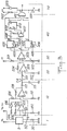
- an igniter device which can be broken down into two distinct sub-assemblies, namely a detection assembly 1 and an electronic interface circuit 2.
- the detection assembly 1 comprises a detector proper, or sensor 3 capable detect the presence of carbon monoxide in the ambient air.
- the sensor 3 which is of the semiconductor type can be a semiconductor gas detector such as those used as security elements for detecting leaks of combustible gas.
- the sensor 3 may in particular be constituted by agglomerated tin dioxide (SnO 3) of type N.
- the essential characteristic of this semiconductor component is its negative variation in electrical resistance under the action of heat and in the presence, on its surface, of carbon monoxide.
- the sensor 3 which is heated and polarized by the circuit 6, delivers an electrical signal the amplitude of which is a function of the carbon monoxide content of the ambient air.
- the electronic circuit 2 comprises at least one threshold trigger circuit 4 which, when the amplitude of the signal from the sensor 3 exceeds a predetermined value, controls a circuit 5 for firing the mine associated with the igniter 1, 2.
- the value of the threshold voltage of the trigger circuits 4 is adjusted according to the desired sensitivity and takes account of the background noise generated by the detector 1.
- the igniter device 1, 2 which detects the combustion gas nauges from engine sub-assembly of land vehicles, or aircraft, depending on the envisaged applications, can be advantageously linked to a buried omnidirectional anti-tank mine, which can itself even be of the aerosol type or of the type with grenades as in the case of the example of figure 2.
- a first pyrotechnic charge (7) makes the mine leap above the ground then a second explosive charge (8) projects the grenades (9) omnidirectionally in a horizontal plane.
- a holding circuit makes it possible to take into account only signals which not only exceed a predetermined amplitude, but also remain present for a certain time greater than a predetermined duration.
- a first stage 1 comprising a detector 3 with tin dioxide delivering an electrical signal whose amplitude depends on the rate of carbon monoxide of the ambient air, which is itself a function of the concentration of internal combustion engine vehicles and their power.
- the detector 3 is heated from a voltage V c , which is a construction data, and is biased by a resistor 33 from a sinusoidal voltage Vp.
- the alternating signal collected at the terminals of the resistor 33 is transmitted by the capacitor 32 to the rectification-filtering stage 10.
- the stage 10 includes resistors 101, 102 for biasing the inputs of a first operational amplifier 103.
- the resistors 104, 105 and the diodes 106, 107 associated with the amplifier 103 produce with the latter and with a second operational amplifier 111 with which the resistors 108, 109, 110 are associated, a full-wave rectifier assembly.
- the circuit formed by the resistor 112 and the capacitor 113 filters the rectified signal.
- the rectified and filtered signal is then applied via a link capacitor 114 to an amplifier stage 20.
- the amplifier stage 20 detects and amplifies the amplitude variations of the signal from the rectification-filtering stage 10 and includes an operational amplifier 203 associated with resistors 201, 202, 204 which determine the parameters of the amplification stage.
- the signal from the amplifier stage 20 is applied to a threshold detector or trigger 30 which comprises an operational amplifier 303 ensuring the comparison between the amplified signal from the stage 20 and a reference voltage determined by the resistor 301 and a potentiometer 302.
- trigger 30 delivers a positive signal at output (see curves A in Figures 4a and 4b).
- the retaining stage 40 comprises two monostable flip-flops 401 and 402, an RS 410 flip-flop and two AND 411 and NON-AND 407 gates.
- the stage 40 aims to only allow the output of an ET 411 gate signal when a positive signal is maintained long enough at the input of stage 40.
- circuit 40 will be explained by considering the diagram in FIG. 3 and the time diagrams of the signals represented in FIGS. 4a and 4b and corresponding to points A, B, C, D and E of the circuit indicated in FIG. 3.
- the Q output of the flip-flop RS 410 goes to state "1" via the monostable circuit 401 including the rising edge of the signal is transmitted by the differentiating circuit interposed between the monostable circuit 401 and the flip-flop RS 410 and constituted by the capacitor 408 and the resistor 409.
- the duration T, of the metastable state of the monostable circuit 401 is greater than the time T 2 of analysis of the signal determined by the monostable circuit 402. If during the duration T, the output of the trigger 303 returns to the state "0 ", the RS 410 flip-flop is reset to" 0 "via the NAND gate 407 and the AND gate 411 is blocked (FIG. 4b). Otherwise (figure 4a), at the end of the time T 2 , the output of the monostable circuit 402 passes to being "1" and a positive firing signal appears at the output of the AND gate 411.
- the duration T, of the state metastable of the monostable circuit 401 depends on the resistance 403 and capacity 404, while the duration T 2 of the metastable state of the monostable circuit 402 depends on the adjustable resistance 405 and capacity 406.
- the firing signal can only effectively occur after a period of arming delay generated by the circuit 50 comprising a capacitor 501, a resistor 502 and a diode 503, and initialized during power-up. of the electronic assembly.
- the selectivity of the igniter thus comprises two settings: The resistor 302 which makes it possible to adjust the threshold above which the amplitude increases are taken into account and the resistor 405 which determines the time during which the signal must be maintained.
- the first setting depends on the type of sensor used and the sensitivity desired for the igniter.
- the second setting which further minimizes the effect of countermeasures, is used to avoid firing of the mine by an isolated vehicle, since it is not very effective in this case.
- FIG. 5 shows another embodiment of the invention.
- the igniter device of FIG. 5 comprises a seismic detection sub-assembly 11, a carbon monoxide detection sub-assembly 21, a power-up delay stage 31, a control logic circuit 41, a circuit 51 firing and a sub-assembly 61 comprising an energy source and a safety circuit.
- the seismic detection sub-assembly 11 conventionally comprises a seismic sensor 12 capable of emitting an electrical signal which is a function of the seismic vibrations which it receives.
- the signal from sensor 12 is shaped by the branch circuit constituted by capacitor 13 and resistor 14 and applied to an input of an operational amplifier 15.
- a threshold value determined by resistors 16, 17, 18 is applied on the second input of the operational amplifier 15 which emits an output signal when the signal supplied by the sensor 12 allows the application of a signal of sufficiently high amplitude to the second input of the differential amplifier 15.
- the carbon monoxide detection sub-assembly 21 comprises a detector 22 similar to the detectors 3 of FIGS. 1 to 3.
- a heating voltage V is applied to the detector 22 while a DC bias voltage is applied via resistance 23 to detector 22.
- the bias voltage which, at the point of connection between resistance 23 and sensor 22, is a function of the carbon monoxide content of the ambient air, is applied to an input of l operational amplifier 24.
- a threshold value determined by resistors 25 and 26 is applied to the second input of amplifier 24 which thus ensures the role of comparator between the signal from detector 22 and the predetermined threshold value which can be adjusted by resistance 26.
- the circuit 31 composed of the capacitor 32, the resistor 33 and the diode 34 constitutes a conventional delay circuit which, by means of two reversing NAND gates 35 and 36 provides the AND gate 42, 43 with a signal of authorization a predetermined time interval after power up.
- the control logic stage 41 comprising a NAND gate 42 and a NAND reversing gate 43 provides a signal on the basis of the transistor 52 of the firing circuit 51 when the seismic detection sub-assembly 11, the sub-assembly of carbon monoxide detection 21 and the timing sub-assembly 31 each simultaneously provide a positive signal to the input of the logic control stage 41.
- the firing stage 51 is itself conventional.
- the assembly of the capacitor 59 of the resistor 57 and of the diode 58 provides the energy necessary for the ignition.
- the triggering of the ignition of the igniter by the thyristor 55, the trigger of which is connected to the emitter of the transistor 52 is carried out in a conventional manner.
- the collector of transistor 52 is connected to the positive pole of the power source while the emitter of this same transistor is connected to the negative pole via resistor 54 and capacitor 53 connected in parallel.
- Stage 61 of the igniter comprises a DC voltage source 65 and conventional elements of a safety circuit comprising a Darlington circuit 62, a resistor 63 and a transistor 64.
Landscapes
- Engineering & Computer Science (AREA)
- General Engineering & Computer Science (AREA)
- Chemical & Material Sciences (AREA)
- Chemical Kinetics & Catalysis (AREA)
- Electrochemistry (AREA)
- Physics & Mathematics (AREA)
- Health & Medical Sciences (AREA)
- Life Sciences & Earth Sciences (AREA)
- Analytical Chemistry (AREA)
- Biochemistry (AREA)
- General Health & Medical Sciences (AREA)
- General Physics & Mathematics (AREA)
- Immunology (AREA)
- Pathology (AREA)
- Air Bags (AREA)
- Aiming, Guidance, Guns With A Light Source, Armor, Camouflage, And Targets (AREA)
Applications Claiming Priority (2)
| Application Number | Priority Date | Filing Date | Title |
|---|---|---|---|
| FR7909979 | 1979-04-20 | ||
| FR7909979A FR2454601A1 (fr) | 1979-04-20 | 1979-04-20 | Dispositif allumeur pour mines antivehicules omnidirectionnelles |
Publications (2)
| Publication Number | Publication Date |
|---|---|
| EP0018246A1 EP0018246A1 (fr) | 1980-10-29 |
| EP0018246B1 true EP0018246B1 (fr) | 1983-10-12 |
Family
ID=9224524
Family Applications (1)
| Application Number | Title | Priority Date | Filing Date |
|---|---|---|---|
| EP19800400365 Expired EP0018246B1 (fr) | 1979-04-20 | 1980-03-18 | Dispositif allumeur pour mines antivéhicules omnidirectionnelles |
Country Status (3)
| Country | Link |
|---|---|
| EP (1) | EP0018246B1 (https=) |
| DE (1) | DE3065234D1 (https=) |
| FR (1) | FR2454601A1 (https=) |
Family Cites Families (5)
| Publication number | Priority date | Publication date | Assignee | Title |
|---|---|---|---|---|
| US3653324A (en) * | 1970-02-10 | 1972-04-04 | Us Army | Electronic device applicable to ordnance safety and arming systems |
| FR2087004A5 (en) * | 1970-04-16 | 1971-12-31 | Naoyoshi Taguchi | Gas detector using semi-conductor with gasre |
| US3763780A (en) * | 1971-12-16 | 1973-10-09 | Us Army | Mine-actuating system using one-shot mv timing circuit and timed mv feedback inhibitor |
| US4081785A (en) * | 1974-02-13 | 1978-03-28 | The United States Of America As Represented By The Secretary Of The Air Force | Dual class amphibious target discriminator |
| US4007456A (en) * | 1975-12-01 | 1977-02-08 | Craftor Inc. | Gas detecting and warning system |
-
1979
- 1979-04-20 FR FR7909979A patent/FR2454601A1/fr active Granted
-
1980
- 1980-03-18 EP EP19800400365 patent/EP0018246B1/fr not_active Expired
- 1980-03-18 DE DE8080400365T patent/DE3065234D1/de not_active Expired
Also Published As
| Publication number | Publication date |
|---|---|
| EP0018246A1 (fr) | 1980-10-29 |
| DE3065234D1 (en) | 1983-11-17 |
| FR2454601A1 (fr) | 1980-11-14 |
| FR2454601B1 (https=) | 1984-01-20 |
Similar Documents
| Publication | Publication Date | Title |
|---|---|---|
| US3931521A (en) | Dual spectrum infrared fire detector | |
| US5612676A (en) | Dual channel multi-spectrum infrared optical fire and explosion detection system | |
| US5544478A (en) | Optical sensing of combustion dynamics | |
| CA1247208A (en) | Dual spectrum frequency responding fire sensor | |
| US8421015B1 (en) | Position sensing detector focal plane array (PSD-FPA) event detection and classification system | |
| US4296324A (en) | Dual spectrum infrared fire sensor | |
| IL44943A (en) | Fire or explosion detection system with discrimination means operable in accordance with amount of energy generated within a predetermined time duration | |
| FR2589564A1 (fr) | Mine avec capteurs de reveil et de declenchement | |
| FR2514486A1 (fr) | Dispositif de combat contre des buts, tels que blindes ou analogues, au moyen d'une munition pointable sur le but | |
| FR2607585A1 (fr) | Mine a tir indirect d'attaque de vehicule blinde | |
| US7899644B2 (en) | Threat launch detection system and method | |
| US3727553A (en) | Fuze device with target detecting means | |
| EP0018246B1 (fr) | Dispositif allumeur pour mines antivéhicules omnidirectionnelles | |
| FR2483160A5 (fr) | Dispositif de declenchement a sensibilite preetablie pour amorcage electrique de mine | |
| FR2496301A1 (fr) | Dispositif ameliore de detection de feu ou d'explosion | |
| FR2600777A1 (fr) | Dispositif de detection d'une impulsion electromagnetique, due notamment a une explosion nucleaire | |
| FR2859536A1 (fr) | Appareil de detection d'un enroulement secondaire ouvert d'une bobine d'allumage | |
| FR2545599A1 (fr) | Fusee de proximite | |
| BE857439A (fr) | Procede et dispositif de mise a feu selective d'arme a action horizontale. | |
| FR2536534A1 (fr) | Procede et dispositif de detection selective de vehicules | |
| EP0234961B1 (fr) | Dispositif de détection rapide d'incendie | |
| GB2258034A (en) | Target detection | |
| FR2665954A1 (fr) | Procede de commande de mise a feu d'une mine, et mine pourvue d'un dispositif de declenchement fonctionnant selon ce procede. | |
| FR2518737A1 (fr) | Systeme de defense de zone a grenade gyroplanante | |
| FR2537263A2 (fr) | Dispositif destine a engendrer un signal d'amorcage pour missile de survol |
Legal Events
| Date | Code | Title | Description |
|---|---|---|---|
| PUAI | Public reference made under article 153(3) epc to a published international application that has entered the european phase |
Free format text: ORIGINAL CODE: 0009012 |
|
| AK | Designated contracting states |
Designated state(s): BE DE GB NL |
|
| 17P | Request for examination filed |
Effective date: 19810429 |
|
| GRAA | (expected) grant |
Free format text: ORIGINAL CODE: 0009210 |
|
| AK | Designated contracting states |
Designated state(s): BE DE GB NL |
|
| REF | Corresponds to: |
Ref document number: 3065234 Country of ref document: DE Date of ref document: 19831117 |
|
| PLBE | No opposition filed within time limit |
Free format text: ORIGINAL CODE: 0009261 |
|
| STAA | Information on the status of an ep patent application or granted ep patent |
Free format text: STATUS: NO OPPOSITION FILED WITHIN TIME LIMIT |
|
| 26N | No opposition filed | ||
| NLS | Nl: assignments of ep-patents |
Owner name: GIAT INDUSTRIES (SOCIETE ANONYME) TE VERSAILLES, F |
|
| REG | Reference to a national code |
Ref country code: GB Ref legal event code: 732 |
|
| PGFP | Annual fee paid to national office [announced via postgrant information from national office to epo] |
Ref country code: GB Payment date: 19930305 Year of fee payment: 14 |
|
| PGFP | Annual fee paid to national office [announced via postgrant information from national office to epo] |
Ref country code: NL Payment date: 19930331 Year of fee payment: 14 |
|
| PGFP | Annual fee paid to national office [announced via postgrant information from national office to epo] |
Ref country code: BE Payment date: 19930406 Year of fee payment: 14 |
|
| PGFP | Annual fee paid to national office [announced via postgrant information from national office to epo] |
Ref country code: DE Payment date: 19930527 Year of fee payment: 14 |
|
| PG25 | Lapsed in a contracting state [announced via postgrant information from national office to epo] |
Ref country code: GB Effective date: 19940318 |
|
| PG25 | Lapsed in a contracting state [announced via postgrant information from national office to epo] |
Ref country code: BE Effective date: 19940331 |
|
| BERE | Be: lapsed |
Owner name: S.A. GIAT INDUSTRIES Effective date: 19940331 |
|
| PG25 | Lapsed in a contracting state [announced via postgrant information from national office to epo] |
Ref country code: NL Effective date: 19941001 |
|
| GBPC | Gb: european patent ceased through non-payment of renewal fee |
Effective date: 19940318 |
|
| NLV4 | Nl: lapsed or anulled due to non-payment of the annual fee | ||
| PG25 | Lapsed in a contracting state [announced via postgrant information from national office to epo] |
Ref country code: DE Effective date: 19941201 |