EP0018150B1 - Schaltungsanordnung zur Steuerung einer akusto-optischen Zelle mit mehreren Strahlenbündeln - Google Patents
Schaltungsanordnung zur Steuerung einer akusto-optischen Zelle mit mehreren Strahlenbündeln Download PDFInfo
- Publication number
- EP0018150B1 EP0018150B1 EP80301105A EP80301105A EP0018150B1 EP 0018150 B1 EP0018150 B1 EP 0018150B1 EP 80301105 A EP80301105 A EP 80301105A EP 80301105 A EP80301105 A EP 80301105A EP 0018150 B1 EP0018150 B1 EP 0018150B1
- Authority
- EP
- European Patent Office
- Prior art keywords
- frequency
- oscillator
- acousto
- laser beams
- oscillators
- Prior art date
- Legal status (The legal status is an assumption and is not a legal conclusion. Google has not performed a legal analysis and makes no representation as to the accuracy of the status listed.)
- Expired
Links
- 230000005540 biological transmission Effects 0.000 claims 1
- 230000001419 dependent effect Effects 0.000 abstract description 2
- 238000010586 diagram Methods 0.000 description 7
- 230000000694 effects Effects 0.000 description 5
- 230000003287 optical effect Effects 0.000 description 3
- 239000013078 crystal Substances 0.000 description 2
- 230000010355 oscillation Effects 0.000 description 2
- 229940075397 calomel Drugs 0.000 description 1
- ZOMNIUBKTOKEHS-UHFFFAOYSA-L dimercury dichloride Chemical compound Cl[Hg][Hg]Cl ZOMNIUBKTOKEHS-UHFFFAOYSA-L 0.000 description 1
- 230000005764 inhibitory process Effects 0.000 description 1
- 239000000463 material Substances 0.000 description 1
- 238000009877 rendering Methods 0.000 description 1
- 230000003252 repetitive effect Effects 0.000 description 1
- 238000000926 separation method Methods 0.000 description 1
- 238000012800 visualization Methods 0.000 description 1
- XLYOFNOQVPJJNP-UHFFFAOYSA-N water Substances O XLYOFNOQVPJJNP-UHFFFAOYSA-N 0.000 description 1
Images


Classifications
-
- G—PHYSICS
- G02—OPTICS
- G02F—OPTICAL DEVICES OR ARRANGEMENTS FOR THE CONTROL OF LIGHT BY MODIFICATION OF THE OPTICAL PROPERTIES OF THE MEDIA OF THE ELEMENTS INVOLVED THEREIN; NON-LINEAR OPTICS; FREQUENCY-CHANGING OF LIGHT; OPTICAL LOGIC ELEMENTS; OPTICAL ANALOGUE/DIGITAL CONVERTERS
- G02F1/00—Devices or arrangements for the control of the intensity, colour, phase, polarisation or direction of light arriving from an independent light source, e.g. switching, gating or modulating; Non-linear optics
- G02F1/01—Devices or arrangements for the control of the intensity, colour, phase, polarisation or direction of light arriving from an independent light source, e.g. switching, gating or modulating; Non-linear optics for the control of the intensity, phase, polarisation or colour
- G02F1/11—Devices or arrangements for the control of the intensity, colour, phase, polarisation or direction of light arriving from an independent light source, e.g. switching, gating or modulating; Non-linear optics for the control of the intensity, phase, polarisation or colour based on acousto-optical elements, e.g. using variable diffraction by sound or like mechanical waves
- G02F1/113—Circuit or control arrangements
-
- G—PHYSICS
- G02—OPTICS
- G02F—OPTICAL DEVICES OR ARRANGEMENTS FOR THE CONTROL OF LIGHT BY MODIFICATION OF THE OPTICAL PROPERTIES OF THE MEDIA OF THE ELEMENTS INVOLVED THEREIN; NON-LINEAR OPTICS; FREQUENCY-CHANGING OF LIGHT; OPTICAL LOGIC ELEMENTS; OPTICAL ANALOGUE/DIGITAL CONVERTERS
- G02F1/00—Devices or arrangements for the control of the intensity, colour, phase, polarisation or direction of light arriving from an independent light source, e.g. switching, gating or modulating; Non-linear optics
- G02F1/29—Devices or arrangements for the control of the intensity, colour, phase, polarisation or direction of light arriving from an independent light source, e.g. switching, gating or modulating; Non-linear optics for the control of the position or the direction of light beams, i.e. deflection
- G02F1/33—Acousto-optical deflection devices
- G02F1/332—Acousto-optical deflection devices comprising a plurality of transducers on the same crystal surface, e.g. multi-channel Bragg cell
Definitions
- the invention relates to acousto-optical modulators and particularly to a circuit arrangement for controlling a multi-beam acousto-optical cell in which Bragg diffraction is used for the generation of a plurality of outgoing laser beams.
- the DE-A1 2 755 575 relates to a laser operated character generator in which the laser beams that write the characters are generated in a single acousto-optical modulator, and the angles of diffraction of the beams are constant in time.
- VHF oscillators are used and each oscillator is coupled through a respective control stage associated therewith to a respective ultrasonic transducer of the acousto-optical cell.
- the frequency of each oscillator determines the direction of the corresponding outgoing laser beam and its amplitude defines the intensity of this beam.
- the control signals applied to the control inputs of the control stages enable or inhibit the passage of the output voltages of the associated oscillators towards the corresponding ultrasonic transducers.
- acousto-optical modulators e.g. in laser operated character generators
- outgoing laser beams with constant diffraction angles are generated, and these beams are deflected in a direction normal to the common plane of their generation by means of a separate deflecting means (e.g. by swinging mirror or by ah additional acousto-optical modulator).
- the position adjustment of the laser beams in their common plane of generation is carried out generally by means of an additional swinging mirror. Such a position adjustment can be used for compensating the effect of the fluctuation of the rotational speed of the recording cylinder.
- the object of the present invention is to provide a circuit arrangement for controlling an acousto-optical cell that on the basis of the acousto-optical modulator used in the DE-OS 2 755 575 can provide for the accomplishment of the above sketched requirements without the need of using additional active optical devices.
- the object of the invention is attained by providing an apparatus for generating a plurality of out-going laser beams from a single incoming laser beam comprising:
- the circuit arrangement according to the invention provides for the simultaneous generation of outgoing laser beams with constant and adjustable diffraction angles, in which all of the outgoing laser beams lie in a common plane.
- the circuit arrangement according to the invention can have general application in the fields of application of acousto-optical modulators, when there is a need for the simultaneous generation of laser beams having constant and adjustable diffraction angles which beams originate substantially from a common point- source.
- an acousto-optical modulator comprising an acousto-optical cell 2 consisting of a transparent optical medium implemented in the exemplary embodiment in the form of a rectangular block and of ultrasonic transducers 3.
- the functional task of the acousto-optical cell 2 is to generate a plurality of separate outgoing laser beams 8, 11 from an incidental main laser beam 1 in accordance with a predetermined control program.
- the main laser beam 1 enters through the smaller end face of the oblong-shaped prismatical acousto-optical cell 2 which face lies parallel to the plane of propagation of the ultrasonic waves in the cell, and the main beam 1 closes an angle 4, the so called Bragg's angle, with the longitudinal axis of the cell.
- the ultrasonic transducers 3 are separated electrically from each other and they are placed behind each other on the lower surface of the acousto-optical cell 2 along the direction of propagation of the incident main laser beam 1.
- the length of the ultrasonic transducers 3 measured along the path of the laser beams is sufficiently high to ensure that any ultrasonic transducer 3 can generate an ultrasonic field in the acousto-optical cell 2 i.e.
- the acousto-optical medium is made of a material in which the' velocity of propagation of ultrasonic waves is low (e.g. water, or the single crystal of Te0 2 as a paratellurite in the crystalline direction defined by the Miller indices /1, 1, 0/, or the M 92 CI 2 single crystal called as calomel in the crystalline direction of /1, 1, 0/), then the length of the ultrasonic transducers 3 can be as short as to fall in the range of about 1 to 3 mm.
- a material in which the' velocity of propagation of ultrasonic waves is low e.g. water, or the single crystal of Te0 2 as a paratellurite in the crystalline direction defined by the Miller indices /1, 1, 0/, or the M 92 CI 2 single crystal called as calomel in the crystalline direction of /1, 1, 0/
- each of the ultrasonic transducers can be driven by one or more high-frequency oscillators, and then within certain limits regarding the effect of generation of the outgoing laser beams the driving frequency signals have independent roles.
- the linear independency of the ultrasonic transducers on the generated diffracted outgoing laser beams provides the possibility of driving more than one ultrasonic transducer 3 with oscillators having a common frequency, and in that case each of these ultrasonic transducers 3 provides for repetitive diffractions in the acousto-optical medium, in which each of the so generated outgoing laser beams 8, 11 will have the same angle of diffraction determined by the common frequency, i.e. virtually a common outgoing laser beam will be generated that will have an intensity determined by the combined energy of the separate driving signals.
- the ultrasonic transducers 3 are substantially equivalent regarding the generation of the outgoing diffracted laser beams 8, 11, the acousto-optical cell 2 shown in the drawing can be considered in virtue as if it were equipped with a single ultrasonic transducer with increased power capacity into which independent high frequency oscillators were coupled that have independent effects on the generation of the diffracted laser beams.
- the separation of the ultrasonic transducers 3 is required because due to the limited electrical performance of the electrical circuit elements (owing to the generation of intermodulation products and to the attenuation of summing circuits) only a limited number of high frequency oscillators with limited output power can be coupled to an ultrasonic transducer.
- acousto-optical modulators as shown in Figs. 1 to 3 and 5, in which the ultrasonic transducers 3 are formed in a common plane in a side-surface of the prismatical block of the cell, but the transducers can be arranged in different parallel planes, or alternatively the acousto-optical cell 2 can be implemented by a number of independent cells being optically coupled to each other.
- acousto-optical cell 2 does not fall within the scope of the present invention, and in case of the present invention any kind of acousto-optical cell can be used that has one or more ultrasonic transducers, if it can provide for the above described linear independency in view of the generation of the outgoing laser beams.
- the output power of the high frequency oscillators which drive the ultrasonic transducers should be chosen in such a way that the effect of additional diffractions of the already diffracted laser beams caused by ultrasonic fields of other transducers within the acousto-optical medium of the cell should be kept in a negligible level.
- This condition is met when the combined intensity of all of the diffracted outgoing laser beams is smaller than about 40% to 50% of the intensity of the incoming main laser beam 1. In that case each outgoing diffracted laser beam obtains its energy from the main laser beam 1.
- Figs. 1, 2, 3 and 5 show alternative embodiments for controlling the acousto-optical cell 2.
- those elements which have substantially equivalent functions regarding the control of the cell are designated by respective blocks of dashed lines. These elements take part in the control of different ultrasonic transducers 3 and are electrically independent from each other.
- the common designation indicated by the dashed line refers to the identical functional task.
- Fig. 1 a plurality of high frequency oscillators 5 with respective predetermined constant frequencies and a plurality of high frequency oscillators 10 with adjustable frequencies are shown.
- the frequencies of the respective oscillators 5 are designated with symbols f l , f 2 , ... f M .
- the oscillators 10 with adjustable frequencies are designed in such a way that their operational frequencies can be changed within certain limit values in response to respective voltage signals applied to frequency-determining inputs 13 associated with the oscillators 10.
- the operational frequency bands of the adjustable oscillators 10 are chosen in such a way that the bands do not overlap each other, and the first adjustable frequency oscillator 10 will have a frequency band with lower and upper limit frequencies f,, and fa2 and the last "n"-th oscillator will have lower and upper limit frequencies f n , and f "2 .
- the role of the appropriate selection of the bands will be explained later.
- a respective control stage 6 is coupled to each of the high frequency oscillators 5 and 10.
- the control stages 6 are electronic switches, which in response to control inputs 9 associated therewith permit or inhibit the passage of the oscillator outputs towards the ultrasonic transducers.
- the control stages 6 can also be implemented in such a way that in addition to or instead of the above described passage-control they change the output voltages coupled from the osillators towards the ultrasonic transducers.
- the control inputs of the control stages associated with the oscillators 10 with adjustable frequencies have been designated by reference number 12.
- Each of the control stages 6 is coupled through a respective amplifier 7 to one of the ultrasonic transducers 3.
- the amplifiers 7 increase the outputs of the oscillators to a suitable level and act as buffer stages between the oscillators and the ultrasonic transducers.
- each of the constant frequency oscillators 5 When the circuit arrangement shown in Fig. 1 is operating, each of the constant frequency oscillators 5 generates a respective outgoing laser beam 8, and the diffraction angle a of these outgoing beams 8 depends on the predetermined constant frequency of the associated oscillator.
- the adjustable frequency oscillators 10 have non-overlapping frequency bands which differ from the frequencies of the oscillators 5, then each of the oscillators 10 generate a respective outgoing laser beam 11 which has an adjustable diffraction angle differing from that of the constantly diffracted outgoing laser beams. In operation the diffraction angles of the laser beams 11 are changed within respective angle-ranges corresponding to the frequency bands of the associated oscillators 10.
- the diffraction angle of each of the outgoing laser beams 8 and 11 will be different i.e. the path of the outgoing laser beams will not cross each other.
- the control applied to the control stages 6 and the control of the frequency determining inputs 13 determine together the path of the outgoing laser beams in accordance with operational requirements.
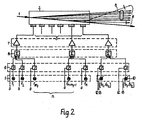
- Fig. 2 shows an arrangement similar to that shown in Fig. 1 and the difference lis in that linear adders 14 are coupled between the respective control stages 6 and the amplifiers 7.
- the linear adders 14 are linear summing circuits with a plurality of inputs, and each of these inputs is coupled to the output of a respective control stage 6.
- the number of the oscillators that can be coupled to an ultrasonic transducer 3 can be increased according to the number of the adder inputs.
- the inputs associated with the last ultrasonic transducer 3 are connected with outputs of control stages 6 driven by adjustable frequency oscillators 10.
- the adders 14 are linear elements, and according to the above described condition relating to the acousto-optical cell 2 stating that each of the ultrasonic transducers 3 has the same effect on the generation of the diffracted outgoing laser beams, the circuit arrangement shown in Fig. 2 does not differ in its operation from that shown in Fig. 1 but it enables the application of more oscillators.
- Fig. 3 shows a further possible embodiment of the invention.
- the difference compared to Fig. 2 lies in that the adjustable frequency oscillators 10 are not coupled now to a single common adder 14, but one input of each adder 14 is coupled to a respective one of the oscillators 10.
- the number of the inputs of the adders 14 shown in Fig. 3 is with one input greater than the number of the inputs of the adders 14 shown in Fig. 2.
- each adder 14 can receive more than one of the adjustable oscillators 10, etc.
- the acousto-optical cell 2 can comprise only two ultrasonic transducers 3, in which one of the two is coupled to a constant frequency oscillator 5 and the other to an adjustable frequency oscillator 10 (according to the arrangement shown in Fig. 1.
- the acousto-optical cell 2 can comprise only a single ultrasonic transducer 3 to which a linear adder 14 is coupled, and a first input of this adder is coupled to a constant frequency oscillator 5 and a second input is coupled to an adjustable frequency oscillator 10.
- the number of the constant frequency oscillators is seven or more.
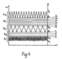
- Fig. 4 shows the time function of the diffraction angles of the outgoing laser beams 8 with constant diffraction angles and of the laser beams 11 with adjustable diffraction angles in case of an exemplary control.
- the control illustrated in Fig. 4 can be carried out by any of the circuit arrangements shown in Figs. 1 to 3.
- Fig. 4 the control diagram of eleven out- going beams with constant diffraction angles and of three outgoing beams with adjustable diffraction angles is shown.
- the left vertical axis represents the diffraction angles a and the right vertical axis the frequencies of the associated oscillators.
- the frequencies of the constant frequency oscillators 5 are divided in two groups.
- the first group comprises the frequencies f, to f 4 that correspond to a deflection range 8b.
- the second group comprises the frequencies f 5 to f" which is associated with a deflection range 8a.
- each outgoing laser beam has a constant diffraction angle, and the associated control stages 6 can exert an influence only on the establishment or inhibition (in given cases also on the intensity) of the tracking path of these beams.
- each of the (in the given case three) outgoing laser beams 11 with adjustable diffraction angle takes a respective angle range 11 a, 11 b or 11 c.
- triangular voltage signals of different frequencies are supposed to be coupled to frequency determining inputs 13 of the adjustable frequency oscillators 10. If all outgoing laser beams are deflected parallel to the horizontal time axis of Fig. 4, then the curve will show also the tracking path of the beams.
- the laser beams 11 with adjustable angles can completely illuminate respective tracking bands, and this feature is advantageous in certain fields of applications (e.g. for the coverage of spaces between lines or of complete tracking bands).
- the respective bands or ranges
- Fig. 5 shows a further embodiment of the circuit arrangement according to the invention.
- This embodiment is developed substantially from the circuit shown in Fig. 3, and the difference lies in, that mixers 15 are coupled between the linear adders 14 and the amplifiers 7.
- Each of the mixers 15 comprises first and second inputs 16 and 17.
- Each first input 16 is connected to the output of the adder associated with the corresponding mixer.
- the second inputs 17 are all connected in parallel and coupled to the output of an auxiliary oscillator 18 that has adjustable frequency.
- the frequency of the auxiliary oscillator 18 can be adjusted within a band defined between limit frequencies F l and F 2 by applying an appropriate voltage to a control input 19 thereof.
- the mixers 15 supply the difference or sum frequency of the high frequency signals coupled to their first and second inputs 16 and 17, and the so obtained product signal drive the ultrasonic transducers 3 of the acousto-optical cell 2.
- the amplifiers 7 are tuned band amplifiers which enable the passage only of the frequency components in the desired range to the ultrasonic transducers 3 which latter have also band-pass characteristics. It is preferable when the frequencies are adjusted so that the difference frequencies fall in the operational range of the ultrasonic transducers 3.
- Fig. 6 is a time diagram of the diffraction angle of the outgoing laser beams which is similar to the diagrams of Fig. 4, and it illustrates the application of the circuit according to Fig. 5, and for the sake of better visualisation a specific control voltage was supposed to be applied to the control input 19 of the auxiliary oscillator 18, and its output frequency F corresponds to this voltage signal. It can be seen in Fig. 6 that the configuration illustrated in Fig. 4 follows the shape of the control voltage of the auxiliary oscillator 18, i.e. all outgoing laser beams will simultaneously and uniformly be deflected.
- the so obtained beam deflection can be used for the common correction of the position of the outgoing laser beams, or for their fine position adjustment.
- the acousto-optical modulator is used in a laser operated character generator, then the outgoing laser beams define e.g. the vertical points of a pattern or of a character, and the deflection of the laser beams perpendicular to their direction of propagation results in the writing of a line of characters.
- the position of the characters perpendicular to the direction of the line deflection e.g. their vertical position
- the circuit arrangement according to the invention makes it possible that in addition to the outgoing laser beams leaving the acousto-optical cell 2 conventionally with respective constant diffraction angles, additional outgoing laser beams can also be generated that propagate in the same plane as the conventional laser beams with constant angles, but their angular deflection (i.e. tracking path) can be adjusted.
- the invention provides also for the common position adjustment of all of the outgoing laser beams within the same plane of propagation. Both of these possibilities can have a number of usage in most fields of applications of the acousto-optical modulators, in particularly in laser operated character generators or in laser operated facsimile equipment.
Landscapes
- Physics & Mathematics (AREA)
- Nonlinear Science (AREA)
- General Physics & Mathematics (AREA)
- Optics & Photonics (AREA)
- Semiconductor Lasers (AREA)
- Lasers (AREA)
- Optical Modulation, Optical Deflection, Nonlinear Optics, Optical Demodulation, Optical Logic Elements (AREA)
- Use Of Switch Circuits For Exchanges And Methods Of Control Of Multiplex Exchanges (AREA)
Claims (6)
dadurch gekennzeichnet, daß die Oszillatoren in einer ersten Gruppe (5) und einer zweiten Gruppe (10) angeordnet sind, wobei jeder Oszillator (fl-f,) der ersten Gruppe (5) eine konstante Frequenz hat, die bestimmend dafür ist, daß der zugeordnete abgehende Laserstrahl (11) in wenigstens einen Bereich von beugungswinkeln fällt, und wobei die zweite Gruppe (10) wenigstens einen Oszillator (fa,- fa2) enthält, dessen Frequenz über einen von einem Wechselsignal beaufschlagten Frequenzsteuereingang (13) einstellbar ist, wodurch der Beugungswinkel eines gegebenen abgehenden Strahles (11) innerhalb eines Bereiches, der den ersterwähnten Bereich nicht überlappt, kontinuierlich veränderbar ist.
Priority Applications (1)
| Application Number | Priority Date | Filing Date | Title |
|---|---|---|---|
| AT80301105T ATE4396T1 (de) | 1979-04-18 | 1980-04-08 | Schaltungsanordnung zur steuerung einer akustooptischen zelle mit mehreren strahlenbuendeln. |
Applications Claiming Priority (2)
| Application Number | Priority Date | Filing Date | Title |
|---|---|---|---|
| HUMA003134 | 1979-04-18 | ||
| HU79MA3134A HU180848B (en) | 1979-04-18 | 1979-04-18 | Multiple acoustooptical,multiray intensity modulator and ray deflector |
Publications (2)
| Publication Number | Publication Date |
|---|---|
| EP0018150A1 EP0018150A1 (de) | 1980-10-29 |
| EP0018150B1 true EP0018150B1 (de) | 1983-08-03 |
Family
ID=10999076
Family Applications (1)
| Application Number | Title | Priority Date | Filing Date |
|---|---|---|---|
| EP80301105A Expired EP0018150B1 (de) | 1979-04-18 | 1980-04-08 | Schaltungsanordnung zur Steuerung einer akusto-optischen Zelle mit mehreren Strahlenbündeln |
Country Status (9)
| Country | Link |
|---|---|
| US (1) | US4371964A (de) |
| EP (1) | EP0018150B1 (de) |
| JP (1) | JPS55142313A (de) |
| AT (1) | ATE4396T1 (de) |
| DD (1) | DD150816A5 (de) |
| DE (1) | DE3064475D1 (de) |
| HU (1) | HU180848B (de) |
| PL (1) | PL128757B1 (de) |
| SU (1) | SU984418A3 (de) |
Families Citing this family (20)
| Publication number | Priority date | Publication date | Assignee | Title |
|---|---|---|---|---|
| USRE33931E (en) * | 1981-12-21 | 1992-05-19 | American Semiconductor Equipment Technologies | Laser pattern generating system |
| EP0100238B1 (de) * | 1982-07-27 | 1991-06-26 | Hoya Corporation | Akustooptisches Modulationselement und Vorrichtung mit einem solchen Element |
| DE3472322D1 (en) * | 1983-08-26 | 1988-07-28 | Hitachi Ltd | Optical information recording and reproducing apparatus |
| FR2575840B2 (fr) * | 1984-01-10 | 1987-06-12 | Sfena | Deflecteur acousto-optique polychromatique |
| FR2557985B1 (fr) * | 1984-01-10 | 1987-04-24 | Sfena | Deflecteur acousto-optique polychromatique |
| US4636718A (en) * | 1984-07-20 | 1987-01-13 | Sperry Corporation | Acousto-optical spectrum analyzer with expanded frequency resolution |
| FR2597987B2 (fr) * | 1986-04-25 | 1991-05-10 | Sfena | Deflecteur acousto-optique polychromatique |
| US5208697A (en) * | 1990-03-30 | 1993-05-04 | Hughes Aircraft Company | Microwave frequency range electro-optic modulator with efficient input coupling and smooth wideband frequency response |
| US5959702A (en) * | 1996-10-04 | 1999-09-28 | Goodman; John Mott | Lensless video projector |
| US5963569A (en) * | 1997-03-28 | 1999-10-05 | International Business Machines Corporation | Multiple channel acousto-optic modulators |
| US5981903A (en) * | 1997-03-28 | 1999-11-09 | International Business Machines Corporation | Laser system for simultaneous texturing of two sides of a substrate |
| US7003003B2 (en) * | 2003-07-21 | 2006-02-21 | Coherent, Inc. | Method and apparatus for providing multiple independently controllable beams from a single laser output beam |
| DE112005001324T5 (de) * | 2004-06-07 | 2007-08-23 | Electro Scientific Industries, Inc., Portland | AOM-Modulationstechniken zur Verbesserung von Lasersystemleistung |
| GB0617945D0 (en) | 2006-09-12 | 2006-10-18 | Ucl Business Plc | Imaging apparatus and methods |
| US20090052010A1 (en) * | 2007-08-23 | 2009-02-26 | Raymond Michaud | Apparatus for providing multiple independently controllable beams from a single laser output beam and delivering the multiple beams via optical fibers |
| US7675673B2 (en) * | 2008-03-26 | 2010-03-09 | Coherent, Inc. | Apparatus for providing multiple time-division multiplexed independently controllable pulsed beams from a single, pulsed laser output-beam |
| GB201006679D0 (en) | 2010-04-21 | 2010-06-09 | Ucl Business Plc | Methods and apparatus to control acousto-optic deflectors |
| GB201106787D0 (en) | 2011-04-20 | 2011-06-01 | Ucl Business Plc | Methods and apparatus to control acousto-optic deflectors |
| EP3074814B1 (de) * | 2013-11-28 | 2019-10-23 | Femtonics Kft. | Akustooptischer ablenker mit mehreren elektroakustischen wandlern |
| US11187962B2 (en) * | 2018-12-14 | 2021-11-30 | Mycronic AB | Reducing impact of cross-talk between modulators that drive a multi-channel AOM |
Family Cites Families (6)
| Publication number | Priority date | Publication date | Assignee | Title |
|---|---|---|---|---|
| DE2061694C3 (de) * | 1970-12-15 | 1973-09-13 | Siemens Ag, 1000 Berlin U. 8000 Muenchen | Akustooptischer Lichtablenker mit erhöhter Bandbreite |
| US3727062A (en) * | 1972-03-10 | 1973-04-10 | Zenith Radio Corp | Acousto-optic information translation system with reference beam for control purposes |
| JPS49134340A (de) * | 1973-04-26 | 1974-12-24 | ||
| US3935566A (en) * | 1973-10-26 | 1976-01-27 | Zenith Radio Corporation | Multiple-channel information translation system and method |
| US3900851A (en) * | 1974-01-07 | 1975-08-19 | Abex Corp | Multi-channel wideband oscillograph |
| JPS5133521A (ja) * | 1974-09-14 | 1976-03-22 | Canon Kk | Hikarijohokirokusochi |
-
1979
- 1979-04-18 HU HU79MA3134A patent/HU180848B/hu not_active IP Right Cessation
-
1980
- 1980-04-08 AT AT80301105T patent/ATE4396T1/de active
- 1980-04-08 US US06/138,420 patent/US4371964A/en not_active Expired - Lifetime
- 1980-04-08 EP EP80301105A patent/EP0018150B1/de not_active Expired
- 1980-04-08 DE DE8080301105T patent/DE3064475D1/de not_active Expired
- 1980-04-14 DD DD80220436A patent/DD150816A5/de not_active IP Right Cessation
- 1980-04-18 SU SU802910501A patent/SU984418A3/ru active
- 1980-04-18 PL PL1980223587A patent/PL128757B1/pl unknown
- 1980-04-18 JP JP5154780A patent/JPS55142313A/ja active Pending
Also Published As
| Publication number | Publication date |
|---|---|
| SU984418A3 (ru) | 1982-12-23 |
| PL128757B1 (en) | 1984-02-29 |
| EP0018150A1 (de) | 1980-10-29 |
| PL223587A1 (de) | 1981-02-27 |
| DD150816A5 (de) | 1981-09-16 |
| US4371964A (en) | 1983-02-01 |
| ATE4396T1 (de) | 1983-08-15 |
| DE3064475D1 (en) | 1983-09-08 |
| HU180848B (en) | 1983-04-29 |
| JPS55142313A (en) | 1980-11-06 |
Similar Documents
| Publication | Publication Date | Title |
|---|---|---|
| EP0018150B1 (de) | Schaltungsanordnung zur Steuerung einer akusto-optischen Zelle mit mehreren Strahlenbündeln | |
| US11409184B2 (en) | Acousto-optic deflector with multiple output beams | |
| US4321564A (en) | Sequential beam switching of acousto-optic modulator | |
| US9958711B1 (en) | Control system using a phase modulation capable acousto-optic modulator for diverting laser output intensity noise to a first order laser light beam and related methods | |
| EP3319185B1 (de) | Mehrkanal-phasenfähiger akustooptischer modulator (aom) und zugehörige verfahren | |
| US3435228A (en) | Light beam controlling system | |
| GB1472274A (en) | Surface wave transducer array and acousto-optical deflector system or frequency-selective transmission system utilising the same | |
| US3736045A (en) | Fast optical guided wave modulator and digital deflector | |
| US3424906A (en) | Light-sound interaction system with acoustic beam steering | |
| US3502879A (en) | Light scanning device | |
| US4381887A (en) | Simplified acousto-optic deflector using electronic delays | |
| Lee et al. | Wide-band guided wave acoustooptic Bragg deflector using a tilted-finger chirp transducer | |
| US5742425A (en) | Technique for electronically stabilizing the ouputs of acoustooptic devices | |
| WO2001014925A9 (en) | Thermally balanced acousto-optic modulator | |
| US5138482A (en) | Light modular and recording device employing same | |
| US4941722A (en) | Light beam deflector | |
| EP3531197B1 (de) | Steuerungssystem mit einem strahlstabilisator und einem phasenmodulierbaren akusto-optischen modulator zum ablenken von laserausgangsintensitätsrauschen auf einen laserlichtstrahl erster ordnung und zugehörige verfahren | |
| CA1176302A (en) | Circuit arrangement for controlling a multi-beam acousto-optical cell in which bragg diffraction is used for the generation of a plurality of outgoing laser beams | |
| US4929043A (en) | Light beam deflector | |
| US4025166A (en) | Acousto-optic light beam scanner | |
| US3637292A (en) | Acousto-optical display device | |
| CN114631054A (zh) | 声光装置的热稳定化 | |
| RU2031426C1 (ru) | Способ сканирования светового пучка | |
| JPH03179326A (ja) | 光変調装置および記録装置 | |
| JPH02930A (ja) | 光偏向装置 |
Legal Events
| Date | Code | Title | Description |
|---|---|---|---|
| PUAI | Public reference made under article 153(3) epc to a published international application that has entered the european phase |
Free format text: ORIGINAL CODE: 0009012 |
|
| AK | Designated contracting states |
Designated state(s): AT BE DE FR GB NL SE |
|
| 17P | Request for examination filed |
Effective date: 19810408 |
|
| GRAA | (expected) grant |
Free format text: ORIGINAL CODE: 0009210 |
|
| AK | Designated contracting states |
Designated state(s): AT BE DE FR GB NL SE |
|
| PG25 | Lapsed in a contracting state [announced via postgrant information from national office to epo] |
Ref country code: SE Effective date: 19830803 Ref country code: NL Effective date: 19830803 Ref country code: BE Effective date: 19830803 |
|
| REF | Corresponds to: |
Ref document number: 4396 Country of ref document: AT Date of ref document: 19830815 Kind code of ref document: T |
|
| REF | Corresponds to: |
Ref document number: 3064475 Country of ref document: DE Date of ref document: 19830908 |
|
| ET | Fr: translation filed | ||
| NLV1 | Nl: lapsed or annulled due to failure to fulfill the requirements of art. 29p and 29m of the patents act | ||
| PLBE | No opposition filed within time limit |
Free format text: ORIGINAL CODE: 0009261 |
|
| STAA | Information on the status of an ep patent application or granted ep patent |
Free format text: STATUS: NO OPPOSITION FILED WITHIN TIME LIMIT |
|
| 26N | No opposition filed | ||
| PGFP | Annual fee paid to national office [announced via postgrant information from national office to epo] |
Ref country code: DE Payment date: 19890630 Year of fee payment: 10 |
|
| PGFP | Annual fee paid to national office [announced via postgrant information from national office to epo] |
Ref country code: AT Payment date: 19900322 Year of fee payment: 11 |
|
| PGFP | Annual fee paid to national office [announced via postgrant information from national office to epo] |
Ref country code: GB Payment date: 19900331 Year of fee payment: 11 |
|
| PGFP | Annual fee paid to national office [announced via postgrant information from national office to epo] |
Ref country code: FR Payment date: 19900405 Year of fee payment: 11 |
|
| PG25 | Lapsed in a contracting state [announced via postgrant information from national office to epo] |
Ref country code: DE Effective date: 19910101 |
|
| PG25 | Lapsed in a contracting state [announced via postgrant information from national office to epo] |
Ref country code: GB Effective date: 19910408 Ref country code: AT Effective date: 19910408 |
|
| GBPC | Gb: european patent ceased through non-payment of renewal fee | ||
| PG25 | Lapsed in a contracting state [announced via postgrant information from national office to epo] |
Ref country code: FR Effective date: 19911230 |
|
| REG | Reference to a national code |
Ref country code: FR Ref legal event code: ST |