EP0017501A1 - A method of and apparatus for extruding plastics products - Google Patents
A method of and apparatus for extruding plastics products Download PDFInfo
- Publication number
- EP0017501A1 EP0017501A1 EP80301097A EP80301097A EP0017501A1 EP 0017501 A1 EP0017501 A1 EP 0017501A1 EP 80301097 A EP80301097 A EP 80301097A EP 80301097 A EP80301097 A EP 80301097A EP 0017501 A1 EP0017501 A1 EP 0017501A1
- Authority
- EP
- European Patent Office
- Prior art keywords
- extrusion
- die
- passage
- supply
- plastics
- Prior art date
- Legal status (The legal status is an assumption and is not a legal conclusion. Google has not performed a legal analysis and makes no representation as to the accuracy of the status listed.)
- Withdrawn
Links
Images


Classifications
-
- B—PERFORMING OPERATIONS; TRANSPORTING
- B29—WORKING OF PLASTICS; WORKING OF SUBSTANCES IN A PLASTIC STATE IN GENERAL
- B29C—SHAPING OR JOINING OF PLASTICS; SHAPING OF MATERIAL IN A PLASTIC STATE, NOT OTHERWISE PROVIDED FOR; AFTER-TREATMENT OF THE SHAPED PRODUCTS, e.g. REPAIRING
- B29C48/00—Extrusion moulding, i.e. expressing the moulding material through a die or nozzle which imparts the desired form; Apparatus therefor
- B29C48/25—Component parts, details or accessories; Auxiliary operations
- B29C48/36—Means for plasticising or homogenising the moulding material or forcing it through the nozzle or die
- B29C48/50—Details of extruders
- B29C48/695—Flow dividers, e.g. breaker plates
- B29C48/70—Flow dividers, e.g. breaker plates comprising means for dividing, distributing and recombining melt flows
-
- B—PERFORMING OPERATIONS; TRANSPORTING
- B29—WORKING OF PLASTICS; WORKING OF SUBSTANCES IN A PLASTIC STATE IN GENERAL
- B29C—SHAPING OR JOINING OF PLASTICS; SHAPING OF MATERIAL IN A PLASTIC STATE, NOT OTHERWISE PROVIDED FOR; AFTER-TREATMENT OF THE SHAPED PRODUCTS, e.g. REPAIRING
- B29C48/00—Extrusion moulding, i.e. expressing the moulding material through a die or nozzle which imparts the desired form; Apparatus therefor
- B29C48/03—Extrusion moulding, i.e. expressing the moulding material through a die or nozzle which imparts the desired form; Apparatus therefor characterised by the shape of the extruded material at extrusion
- B29C48/09—Articles with cross-sections having partially or fully enclosed cavities, e.g. pipes or channels
-
- B—PERFORMING OPERATIONS; TRANSPORTING
- B29—WORKING OF PLASTICS; WORKING OF SUBSTANCES IN A PLASTIC STATE IN GENERAL
- B29C—SHAPING OR JOINING OF PLASTICS; SHAPING OF MATERIAL IN A PLASTIC STATE, NOT OTHERWISE PROVIDED FOR; AFTER-TREATMENT OF THE SHAPED PRODUCTS, e.g. REPAIRING
- B29C48/00—Extrusion moulding, i.e. expressing the moulding material through a die or nozzle which imparts the desired form; Apparatus therefor
- B29C48/16—Articles comprising two or more components, e.g. co-extruded layers
- B29C48/18—Articles comprising two or more components, e.g. co-extruded layers the components being layers
- B29C48/21—Articles comprising two or more components, e.g. co-extruded layers the components being layers the layers being joined at their surfaces
-
- B—PERFORMING OPERATIONS; TRANSPORTING
- B29—WORKING OF PLASTICS; WORKING OF SUBSTANCES IN A PLASTIC STATE IN GENERAL
- B29C—SHAPING OR JOINING OF PLASTICS; SHAPING OF MATERIAL IN A PLASTIC STATE, NOT OTHERWISE PROVIDED FOR; AFTER-TREATMENT OF THE SHAPED PRODUCTS, e.g. REPAIRING
- B29C48/00—Extrusion moulding, i.e. expressing the moulding material through a die or nozzle which imparts the desired form; Apparatus therefor
- B29C48/25—Component parts, details or accessories; Auxiliary operations
- B29C48/255—Flow control means, e.g. valves
- B29C48/2556—Flow control means, e.g. valves provided in or in the proximity of dies
-
- B—PERFORMING OPERATIONS; TRANSPORTING
- B29—WORKING OF PLASTICS; WORKING OF SUBSTANCES IN A PLASTIC STATE IN GENERAL
- B29C—SHAPING OR JOINING OF PLASTICS; SHAPING OF MATERIAL IN A PLASTIC STATE, NOT OTHERWISE PROVIDED FOR; AFTER-TREATMENT OF THE SHAPED PRODUCTS, e.g. REPAIRING
- B29C48/00—Extrusion moulding, i.e. expressing the moulding material through a die or nozzle which imparts the desired form; Apparatus therefor
- B29C48/25—Component parts, details or accessories; Auxiliary operations
- B29C48/30—Extrusion nozzles or dies
- B29C48/32—Extrusion nozzles or dies with annular openings, e.g. for forming tubular articles
- B29C48/335—Multiple annular extrusion nozzles in coaxial arrangement, e.g. for making multi-layered tubular articles
- B29C48/336—Multiple annular extrusion nozzles in coaxial arrangement, e.g. for making multi-layered tubular articles the components merging one by one down streams in the die
- B29C48/3366—Multiple annular extrusion nozzles in coaxial arrangement, e.g. for making multi-layered tubular articles the components merging one by one down streams in the die using a die with concentric parts, e.g. rings, cylinders
Definitions
- THIS INVENTION relates to a method of and apparatus for extruding plastics products and to plastics proqucts produced by the method or using the apparatus.
- plastics products different parts of which have a different composition and/or different characteristics.
- the exterior of the pipe should be resistant to moisture or sunlight, that the inner surface of the tube be resistant to attack by a particular liquid and that wall of the tube as a whole should have good heat insulating properties.
- an extrusion die for use in extruding plastics pipes of the kind comprising a plurality of concentric layers of different composition and/or characteristics, the die comprising a central mandrel and an outer die structure encircling the mandrel and defining, with the mandrel, an annular-section extrusion passage extending to an annular extrusion outlet of the die, and a plurality of supply passages for plastier materialk, said supply passages communicating with said extrusion passage at different axial positions upstream of their extrusion outlet, at least one said supply passage including, at some position therealong, or at its outlet when it meets said extrusion passage, an annular gap defined between opposing surfaces, one of which is provided by a member which is adjustable transversely of the longitudinal axis of the die.
- Such adjustability of said member transversely of the die axis may be used, for example, to vary or eliminate eccentricity of the member with respect to the die axis, and/or to vary the direction, transverse to the die axis, in which the centre of said member is displaced from the die axis, with a view, in each case, to modifying the flow of plastics along the supply passage as desired.
- each said supply passage is annular in cross section and in axial section slopes, in the direction of extrusion the extrusion passage, from an inlet end thereof to said extrusion passage, one of the opposing surfaces defining said annular gap being disposed radially outwardly of the other whereby such adjustment of the eccentricity of said member varies the width of said annular gap locally.
- each said supply passage is provided in said outer die structure and the respective said adjustable member is in the form of a ring which provides the radially outer suriaces of the respective annular gap, the ring being adjustably supported by screws extending generally radially through a fixed part of the outer die structure to engage the circumference of the ring.
- apparatus for use in extruding plastics products of the kind comprising a plurality of layers of different composition and/or characteristics and including an extrusic die having a plurality of supply passages communicating witl a common extrusion passage, the apparatus including plastics supply means for supplying plasticised plastics under pressure to said supply passages of the die, said plastics supply means having associated therewith means operable, in use of the- apparatus, to effect dynamic adjustment of the thickness of one or more layers of the extruded product.
- Said plastics supply moans may include plastics supply conduits having adjustable flow controlling valves therein whereby the rates of flow of plastics to the respective supply passages, and the thicknesses of the corresponding layers of the extruded product, may be readily adjusted during operation of the apparatus.
- said supply means includes at least one supply conduit which branches into at least two further supply conduits, each of said further supply conduits being connected with a respective said supply passage of the die, and each of said further supply conduits having a respective flow controlling valve therein.
- a mothed of producing an extruded multi-layered plastics product using the apparatus according to the second-mentioned aspeet of the invention, comprising supplying plastiaised plastics material via said supply conduits to said supply passages, to pass in the desired manner to said extrusion passage, and adjusting the thickness of one or more layers of the product extruded, during the extrusion of the product, by operation of said adjustment means associated with the plastics supply means.
- means for supplying and distributing plasticised synthetic plastics material to an extrusion head, mould, or the like comprising a body providing an inlet passage for plasticised plastics extending from an inlet opening and branching into a plurality of outlet passages leading to respective outlet openings, at least one said outlet passage having flow controlling means disposed therein and adjustable to control the flow cross-section through the passage in which it is disposed.
- the invention also comprehends within its scope a multi-layered plastics product formed in apparatus embodying the invention, or by a process in accordance with the invention.
- the die comprises a base member 9 having a first portion in the form of a thick metal disc and a second portion in the form of a cylindrica stem 15 of substantially smaller diameter than the disc extending from one face of the disc, the stem 15 being coaxial with the disc.
- the stem 15 and mandrel part 1 are of circular cross sectic throughout.
- T1 plates 4 to 8 and the base member 9 are held together by tie bolts distributed at regular intervals around the circumference of the die, each said tie bolt extending parallel with the die axis through aligned bores in the members 4 to 9.
- a front die member 2 in tho form of an externally cylindrical forward part extending coaxially from an outwardly cylindrical root part of greater diameter than the forward part is retained in a recess in the die plate 4 by means of a retaining plate 3.
- the front die part 2 has a central passage therethrough, the portion '6 of said passage which is within the forward portion of the front die part 2 being cylindrical and coaxial with the outer surface of said forward part, whereas the part 18 of said central passage which extends through said root portion of the front die part is frusto-conical in form converging in the forward direction and being coaxial with said cylindrical bore.
- a planar annular shoulder 20 extends between the outer surface of the forward portion of the front die part and the outer surface of the root portion of the front die part.
- the recess in the die plate 4 in which the front die part is accommodated is in the form of a cylindrical bore 22 extending axially into the plate 4 from the front face thereof, the diameter of the bore 22 being substantially greater than the external diameter of the root portion of the front die part 2 accommodated therein.
- the front retaining plate 3 is in the form of an annular disc with planar end faces, the forward portion of the front die part 2 extending through the central aperture in the retaining plate 3 with substantial diametral clearance.
- the die plate 3 is received snugly in a shallow counterbore 24 extending from the front face of the die plate 4 coaxial with the bore 22, the front retaining plate 3 being clamped to the die plate 4 by means of a plurality of clamping bolts, (not shown), regularly distributed around the retaining plate 3, said bolts extending, parallel with the die axis, through respective bores in the plate 3 and engaging in respective screw threaded bores in the plate 4.
- means for centering the die part 2 with respect to the die plates, or varying the eccentricity of the die part 2 with respect to the die plates, said means comprising four adjustment bolts each received in a respective screw threaded bore extending radially through the die plate 4 into the bore 22 to engage, at its inner end, the periphery of the root portion of the front die part 2.
- the bolts 30 are disposed at intervals of 90° around the axis of the die plate 4 and have projecting heads accessible for adjustment.
- the die plates 4 to 8 and the mandrel 15, 1 together define, in conjunction with the front die part 2 and equalisation rings 11 and 12 discussed in more detail below, an annular extrusion passage opening in an annular outlet defined between the mandrel part 1 and the front die part 2.
- the die plate 8 comprises a base portion 8a having the general form of a flat disc, the rear face of which engages the front end face of the first part of the base member 9, and a part 8b which has the form of a tubular spigot extending forwardly from the part 8a, the exterior of said spigot tapering frusto-conically in the forward direction.
- An axial bore 36 extending through the portions 8a and 8b is, over a major part of the length of said bore extending from the rear face of the part 8a, a close sealing fit around the corresponding portion of the part 15.
- annular groove 38 is formed in the part 15, defining, with the opposing internal wall of the spigot part 8b an annular plenum chamber 40.
- the part 15 is reduced slightly in diameter downstream of the groove 38 and the axial bore through the spigot part 8b is enlarged in diameter from the rearwardmost edge of the groove 38 to the front end of the spigot member to define, extending from the plenum chamber 40 to the extrusion passage proper, (which may be regarded as commencing just downstream of the front end of the spigot part 8b), an annular plastics supply passage 41.
- the plenum chamber 40 is connected via inclined bores 42 in the part 15 with an axial bore 43 extending rearwardly in the base member 9, the bore 43 being connected in turn with a radial bore 44 opening in an inlet orifice on the periphery of the first part of member 9.
- plasticised plastics material may be supplied to the plenum chamber 40 via the bores 44, 43 and 42 to pass from the chamber 40 to the extrusion passage proper.
- a second plenum chamber, 46 is defined partly by an annular groove formed around the spigot portion 8b of the die plate 8 in the front end face of the die plate 8 and partly by an annular groove formed in the die plate 7 and forming the transition between the rear end face of the die plate 7 and the axial passage through the die plate 7, and this plenum chamber 46 is connected with the extrusion passage proper via a passage 48 which is annular in cross section and is of generally frusto-conical form, sloping, in the forward direction from the plenum chafer 46, towards the central axis of the die.
- the passage 48 is defined between, on the one hand, the outer surface of the spigot part 8b of the die plate 8, and, on the other hand, a part 49 of the passage through the die plate 7, the internal passage through the equalisation ring 11, and the rearward portion of the internal axial passage through the die plate 6, the die plate 6 having a rear face engaging the front face of the die plate 7.
- the die plate 6 like the die plate 8, comprises a rear portion 6a in the general form of a flat disc and a spigot portion 6b extending axially forwards from the spigot portion 6a.
- the outer surface of the spigot portion 6b is substantially frusto-conical, tapering forwardly from the portion 6a, and in this case the axial bore through the die plate 6 tapers frusto-conically from the rear face of the part 6a to a position somewhat downstream of the position of the front end of the spigot portion 8b, (this tapering portion of the passage through die plate 6a partly defining the radially outer wall of the frusto-conically tapering passage 48), whilst the remainder of the bore through the die plate 6 is substantially cylindrical.
- a third annular plenum chamber 50 is defined partly by an annular groove formed in the front face of the disc part 6a around the root of the spigot part 6b and parsly by an annular groove formed in the die plate 5 and forming the transition between the rear face of die plate 5 which engages the front face of die plate 6 and the axial passage through the die plate 5.
- the plenum chamber 50 is also connected with the extrusion passage by a passage 52 of annular cross section tapering forwardly from the plenum chamber 50 towards the die axis, the passage 52 being defined between the outer surface of the spigot part 6b and an opposing, correspondingly frusto-conical surface defined partly by the axial passage through the die plate 5 and partly by the axial passage through the equalisation ring 12.
- the edualisation rings 11 and 12 are adjustably mounted in the die in a manner similar to the root portion of the front die part 2.
- the rings 11 1 and 12 which are externally cylindrical and have planar end faces are accommodated in respective radially inwardly open annular channels defined by cylindrical counter bores 56, 54, respectively in the die plates 7, 5, respectively and adjoining lear end faces of the die plates 6, 4, respectively.
- Each ring 11, 12, has an external diameter substantially smaller than that of the respective bore 56, 54, and is slidable transversely, without appreciable axial play, between the planar end wall of the respective bore 56, 54 respectively and the opposing planar end face of the respective plates 6, 4, said opposing planar faces slidably engaging the opposing planar end faces of the respective rings.
- each ring 11, 12, relative to the die axis is adjustable by means of four adjustment bolts, not shown, the respective set of four adjustment bolts for each ring 11, 12 being distributed at intervals of 90° around the die and being screw-threadedly engaged in respective radial bores in the respective die plates 7, 5, the adjustment bolts of each set extending, at their inner ends, into the respective bome 56. 54, to engage the periphery of the respective ring 1, 12.
- a rearward part of the bore therethrough is frust-conical, tapering in the forward direction whilst the forward part of the bore therethrough is substantially cylindrical.
- the cylindrical portion of the bore through the ring defines the outer wall of the annular extrusion passage proper which lies immediately downstream of the front end of the spigot part 6b, the last mentioned part of the extrusion passage being of greater external diameter than the part immediately upstream provided by the interior of the spigot part 6b.
- the cylindrical portion of the bore through the ring together with a correspondingly cylindrical portion of the bore through die plate 6 adjacent the rear end of the latter, defines, with the opposing frusto-conical outer surface of the spigot part 8b, a section of passage 48 which increases progressively in flow cross-section towards the extrusion passage proper, the flow cross-section of the part of passage 48 downstream of this section being greater than that of the part of passage 48 upstream of this section.
- the part of the mandrel provided by the mandrel part 1 tapers inwardly in the forward direction from an axial position corresponding approximately to that of the ring 12 to an axial position immediately upstream of the rearward end of the cylindrical part of the axial bore through the front die part 2, the portion of the mandrel part 1 passing through said cylinlrical bore in the die part 2 being externally cylindrical and terminating in a cylindrical end part of reduced diameter projecting from the die opening.
- the axial passage through the die plate 4, over the region extending from the rear face of the die plate 4 to the root portion of the front die part 2 tapers frusto-conically inwardly in the forward direction as an extension, (when the part 2 is arranged exactly coaxially with the die plate 4) of the frusto-conical surface of the rearward para of the axial passage through the die part 2, the apex angle of the last-mentioned frusto-conical surface being greater than that of the frusto-conical part of the mandrel part 1 so that the annular extrusion passage not only converges towards the axis of the die from the position of the ring 12 to that of the rear end of the cylindrical part of the bore through the die part 2 but also decreases progressively in radial width over this section.
- the mandrel 15, 1 is externally substantially cylindrical in the region between the groove 38 and a position just downstream of the front end of the spigot part 6b whilst the outer diameter of the extrusion passage, upstream of the front end of the spigot part 6b and downstream of the front end of the spigot part 8b, (said outer diameter being defined by the cylindrical part of the axial bore through the die plate 6), is somewhat less than the outer diameter of the extrusion passage immediately downstream of the front end of the spigot portion 6b.
- the outer diameter of the annular section passage connecting the plenum chamber 40 with the extrusion passage proper downstream of the front end of the spigot portion 8b, said outer diameter being defined by the spigot portion 8b. is substantially less than the outer diameter of the part of the extrusion passage defined by the spigot portion 6b of the die plate 6.
- plasticised plastics material is supplied to the plenum chambers 40, 46, 50 and passes therefrom along the respective passages 41, 48, 52 to the annular extrusion passage, whilst, dae to the noted changes in external diameter of the latter, the flow cross-section of the extrusion passage increases downstream of the point where each of these passages meets the extrusion passage, to accommodate the respective layer of plastics material supplied to the extrusion passage from the respective passage 41, 48, 56.
- a bore 60 extends radially inwardly into the die assembly to communicate with plenum chamber 46, the "axis" of bore 60 lying in the plane of the radially inner part of the joint face between plates 6 and 7.
- a bore 62 extends radially inwardly into the die assembly to communicate with plenum chamber 50, the axis of bore 62 lying in the plane of the radially inner part of the joint face between plates 6 and 7.
- Said first portion of the base member 9 is formed, on its periphery, with a flat perpendicular to bore 44 and onto which the bore 44 opens, a countorbore being formed around said bore 44 and extending from said flat.
- the die plates 7, 8 are provided, on their outer peripheries, with co-planar flats together defining a planar surface perpendicular to bore 60 and onto which bore 60 opens, a shallow counterbore being provided around said bore 60 and extending from said planar surface.
- Similar co-operating flats are provided on the peripheries of the die plates 5 and 6 and define a planar surface, perpendicular to bore 62 and into which bore 62 opens, a shallow counterbore being provided around bore 62 and extending from said planar surface.
- the radially outer ends of the bores 44, 60 and 62, and the respective shallow counterbores receive . fittings for engagement with means for supplying plasticised plastics material under pressure to the plenum chambers 40, 46 and 50 respectively.
- the bores 44, 62 lie on a side of the die assembly which is diametrically opposite that on which the bore 60 lies.
- plasticised plastics is supplied to the die of Figure 1 by supplying means including the device 80 shown in Figure 2.
- the device 80 includes an inlet fitting 82 adapted to receive an outlet nozzle of a plastics-injector (not shown) and two outlet fittings 84 and 86 adapted for sealing engagement with complementary inlet fittings 88 and 90 respectively fitted in the inlets 44 and 62 of the die.
- Each of the fittings 82, 84, 86 has an axial passage therethrough, and the function of the device 80 is simply to piovide a single inlet passage (the inlet to which is afforded by fitting 82) and two branch passages branching from the inlet passage, the branch passages terminating in the fittings 84, 86 respectively, independent flow regulating means being provided in each of the two branch passages.
- the single inlet passage is indicated in broken lines at 92 while the two branch passages are indicated at 94, 96 respectively.
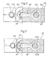
- the major part of the device 80 comprises two similarly profiled superimposed metal plates clamped together by bolts (not shown) the axes of the fittings 82, 86, 84, lying in the parting plane between the two plates.
- the two plates are referenced 98 and 100 in Figures 3 and 4.
- the passages 92, 94, 96 are defined by co-operating roundbottomed grooves in the opposing faces of the plates 98 and 100.
- flow adjustment members 102 and 104 respectively in the form of generally cylindrical bolts having conically tapering noses 102a and 104a respectively within the block said noses extending within the respective regions bounded by respective vaJv 3 seats 102b and 104b formed in the block 98, 100, coaxially with the respective bolts 102, 104, each said surface 102b, 104b forming part of the respective metering chamber formed in the block 98, 100 by co-operating recesses in the plates 98 and 100, each said valve seat surface namely forming the part of the respective metering chamber leading to the outlet therefrom, which outlet is in the form of a straight passage coaxial with the respective bolt 102, 104 and leading to the outlet of the respective fitting 84, 86.
- Each bolt 102, 104 is accommodated in a respective coaxial bore, each bolt 102, 104 being sealingly received in a section 108, 110 respectively of its respective bore which opens into the respective metering chamber.
- Each bolt 102, 104 has, remote from its frusto-conical end, an externally screw-threaded portion 112, 114 respectively of enlarged diameter with respect to the remainder of the bolt End being in screw-threaded engagement with a screw-threaded portion of the respective bore reseiving the bolt, the screw-threaded portion of the respective bore extending to the end face of the plates 98, 100 remote from the fittings 84, 86.
- the bolts 102, 104 may be screwed in or out independently of one another to adjust the axial positions of the respective bolts and thus the flow cross section defined between the cooperating frusto-conical surfaces of the nose of the respective bolt and the respective valve seat.
- the bolts 102, 104 may be fitted with handles to allow such adjustment to be effected manually, but preferably the bolts 102, 104 are coupled to electric motors whereby adjustment may be made automatically, during operation of the apparatus.
- the material for the inner layer is supplied to the plenum chamber 40 via the passages 43 and 44 whilst the material for the outer layer is supplied to the plenum chamber 50 via the bore 62 or a fitting, such as the fitting 88, received therein.
- the material for the foamed intermediate layer, comjprising a plasticised plastics material with a framing agent is supplied under pressure to + he plenum chamber 46 via a fitting (not shown) fitted in the bore 60 in the same way as the fittings 88, 90 may be fitted in the bores 62, 44.
- the adjustable bolts 102, 104 allow the radial thickness of each of the three layers of the pipe to be varied during extrusion of the pipe from the openang between the mandrel part 1 1 and the die part 2, since by adjustment of both bolts 102, 104, simultaneously, the flow rate of the plastics material supplied to the die via passage 92 and fittings 84, 86 may be adjusted relative to the flow rate of the foamable plastics material supplied to the plenum chamber 46, whilst the thickness of the outer layer relative to the inner may be adjusted by adjustment of one of the bolts 102, 104 or adjustment of both bolts in contrary senses.
- Control of the extrusion process is assisted by sensing the fluid pressure in the outlet part of the extrusion passage by means of a pressure transducer.
- the materials of the various layers of the extruded pipe should be selected in accordance with their desired function, and in certain instances considerations of adhesive compatibility between the substances of the various layers and the convenience of using the same plastics material for the inner and outer layer of the pipe must be regarded as secondary.
- the internal wall of the extruded pipe has to withstand the surface pressures or pressures of fluids passing therethrougs and may also be required to be resistant to attack by specified fluids, whereas the outer wall of the pipe may be required to be abrasion resistant or resistant to various weather conditions or soil conditions or the like, and it may be necessary to select a different plastics material for each of the layers.
- each of the passages 44, 60, 62 would be supplied from a respective injector for supplying the respective plastics material under pressure.
- the die might be subdivided still further to provide, between the plenum chambers for the material of the incompatible layers, a further plenum chamber, communicating with the extrusion passage proper via a respective annular flow passage opening into the extrusion passage at a position intermediate the positions where the flow passages for the materials of the incompatible layers open into the extrusion passage, the adhesive being selected to have a good adhesion with the material of either layer, so that during extrusion the inner of the two layers is coated with adhesive before the application of the outer of the two layers, thereby securing adequate bonding between the layers.
- the device of Figures 2 to 4 may incorporate, for purposes of monitoring and control, a temperature sensing device, such as a thermocouple, for sensing the temperature in the passage 92 upstream of the valve seats 102a and 104a, ard/or a respective pressure transducer for sensing the fluid pressure in the respective straight passage leading to the outlet of the respective fitting 84 or 86.
- a temperature sensing device such as a thermocouple
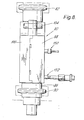
- thermocouple 150 A variant of the device of Figures 2 to 4, incorporating such a thermocouple 150 and such pressure transducers 152, is shown in the accompanying Figures 6 to 8.
Abstract
Apparatus for extrusion of a plastics pipe, comprising a plurality of different layers is disclosed, including an extrusion die having a base-plate (9) with a mandrel (15,1) extending therefrom, a stack of annular die plates (8,7,6, 5 and 4) secured to the base plate and defining with the mandrel (15,1) an annular extrusion passage leading to an annular extrusion outlet (16). Annular plenum chambers (40, 46 and 50) defined respectively between mandrel (15) and plate (8), between plate (8) and plate (7), and between plate (6) and plate (5) respectively lead into the annular extrusion passage upstream of the extrusion opening. Equalisation rings (11 and 12) and a front die member (2) are adjustable diametrally with respect to the mandrel (15) to adjust the concentricity of the different layers in the pipe produced. Molten plastics material may be fed from a single source to the plenum chambers (40 and 50) feeding the material for the inner and outer layers of the pipe via a distributor having separate flow adjusters for each of two conduits connectable with the chambers (40 and 50)
Description
- THIS INVENTION relates to a method of and apparatus for extruding plastics products and to plastics proqucts produced by the method or using the apparatus.
- It is frequently necessary or desirable to produce plastics products different parts of which have a different composition and/or different characteristics. For example, where the product is a plastics pipe, it may be desired that the exterior of the pipe should be resistant to moisture or sunlight, that the inner surface of the tube be resistant to attack by a particular liquid and that wall of the tube as a whole should have good heat insulating properties. furthermore, it is clearly advantageous to be able to produce such a product in a single operation rather than in a plural ty of successive operations.
- It is among the objects of the invention to provide improved mears for and a method of producing such a product.
- According to ong aspect of the invention there is provided an extrusion die for use in extruding plastics pipes of the kind comprising a plurality of concentric layers of different composition and/or characteristics, the die comprising a central mandrel and an outer die structure encircling the mandrel and defining, with the mandrel, an annular-section extrusion passage extending to an annular extrusion outlet of the die, and a plurality of supply passages for plastier materialk, said supply passages communicating with said extrusion passage at different axial positions upstream of their extrusion outlet, at least one said supply passage including, at some position therealong, or at its outlet when it meets said extrusion passage, an annular gap defined between opposing surfaces, one of which is provided by a member which is adjustable transversely of the longitudinal axis of the die.
- Such adjustability of said member transversely of the die axis may be used, for example, to vary or eliminate eccentricity of the member with respect to the die axis, and/or to vary the direction, transverse to the die axis, in which the centre of said member is displaced from the die axis, with a view, in each case, to modifying the flow of plastics along the supply passage as desired.
- Preferably the or each said supply passage is annular in cross section and in axial section slopes, in the direction of extrusion the extrusion passage, from an inlet end thereof to said extrusion passage, one of the opposing surfaces defining said annular gap being disposed radially outwardly of the other whereby such adjustment of the eccentricity of said member varies the width of said annular gap locally.
- Preferably the or each said supply passage is provided in said outer die structure and the respective said adjustable member is in the form of a ring which provides the radially outer suriaces of the respective annular gap, the ring being adjustably supported by screws extending generally radially through a fixed part of the outer die structure to engage the circumference of the ring.
- According to another aspect of the invention there is provided apparatus for use in extruding plastics products of the kind comprising a plurality of layers of different composition and/or characteristics and including an extrusic die having a plurality of supply passages communicating witl a common extrusion passage, the apparatus including plastics supply means for supplying plasticised plastics under pressure to said supply passages of the die, said plastics supply means having associated therewith means operable, in use of the- apparatus, to effect dynamic adjustment of the thickness of one or more layers of the extruded product.'
- Said plastics supply moans may include plastics supply conduits having adjustable flow controlling valves therein whereby the rates of flow of plastics to the respective supply passages, and the thicknesses of the corresponding layers of the extruded product, may be readily adjusted during operation of the apparatus.
- In a preferred form of the apparatus, said supply means includes at least one supply conduit which branches into at least two further supply conduits, each of said further supply conduits being connected with a respective said supply passage of the die, and each of said further supply conduits having a respective flow controlling valve therein.
- According to another aspect of the invention, there is provided a method of producing an extruded, multi-layered plastics tube using the apparatus according to the first- mentioned aspect of the invention, and ir. which method the eccentricity of the or each said member is adjusted to secure the desired concentricity of the various layers in the extruded product.
- According to vet another aspect of the invention, there is provided a mothed of producing an extruded multi-layered plastics product, using the apparatus according to the second-mentioned aspeet of the invention, comprising supplying plastiaised plastics material via said supply conduits to said supply passages, to pass in the desired manner to said extrusion passage, and adjusting the thickness of one or more layers of the product extruded, during the extrusion of the product, by operation of said adjustment means associated with the plastics supply means.
- According to a yet further aspect of the invention there is provided means for supplying and distributing plasticised synthetic plastics material to an extrusion head, mould, or the like, said means comprising a body providing an inlet passage for plasticised plastics extending from an inlet opening and branching into a plurality of outlet passages leading to respective outlet openings, at least one said outlet passage having flow controlling means disposed therein and adjustable to control the flow cross-section through the passage in which it is disposed.
- The invention also comprehends within its scope a multi-layered plastics product formed in apparatus embodying the invention, or by a process in accordance with the invention.
- An embodiment of the invention is described below witl reference to the accompanying drawings in which:-
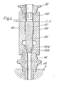
- Figure 1 is a view in axial section of an extrusion die embodying the invention,
- Figure 2 is a plan view of a member affording plastics supply conduits for'the supply of plasticised plastics to the die of Figure 1,
- Figure 3 is a view of the member of Figure 2, partly in end elevation and partly in section, along the line III-A-B-III in Figure 2,
- Figure 4 is a view of the member of Figure 2 in sectic along the line IV-O-D-IV of Figure 2, and
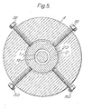
- Figure 5 is a view in cross section along the line V-V of Figure 1.
- Referring to Figure 1, the die comprises a
base member 9 having a first portion in the form of a thick metal disc and a second portion in the form of a cylindrica stem 15 of substantially smaller diameter than the disc extending from one face of the disc, the stem 15 being coaxial with the disc. The forwardmost part of the stem 15, i.e. the part furthest from the said disc, forms a rearward part of a mandrel, the remainder of which is forme by a mandrel part 1 screwed to the front end of the stem 1; The stem 15 and mandrel part 1 are of circular cross sectic throughout. - Mounted in a stack on the
base 9 is a plurality of annular die plates, eferenced, in order of increasing distance from the said first portion of thebase member base member 9 and provided with interengaging annular shoulders and recesses to ensure that this coaxial relationship is maintained.T1 plates 4 to 8 and thebase member 9 are held together by tie bolts distributed at regular intervals around the circumference of the die, each said tie bolt extending parallel with the die axis through aligned bores in themembers 4 to 9. - A front die member 2, in tho form of an externally cylindrical forward part extending coaxially from an outwardly cylindrical root part of greater diameter than the forward part is retained in a recess in the
die plate 4 by means of aretaining plate 3. The front die part 2 has a central passage therethrough, the portion '6 of said passage which is within the forward portion of the front die part 2 being cylindrical and coaxial with the outer surface of said forward part, whereas thepart 18 of said central passage which extends through said root portion of the front die part is frusto-conical in form converging in the forward direction and being coaxial with said cylindrical bore. On the exterior of the front die part, a planarannular shoulder 20 extends between the outer surface of the forward portion of the front die part and the outer surface of the root portion of the front die part. - The recess in the
die plate 4 in which the front die part is accommodated is in the form of acylindrical bore 22 extending axially into theplate 4 from the front face thereof, the diameter of thebore 22 being substantially greater than the external diameter of the root portion of the front die part 2 accommodated therein. Thefront retaining plate 3 is in the form of an annular disc with planar end faces, the forward portion of the front die part 2 extending through the central aperture in theretaining plate 3 with substantial diametral clearance. Thedie plate 3 is received snugly in ashallow counterbore 24 extending from the front face of thedie plate 4 coaxial with thebore 22, the frontretaining plate 3 being clamped to thedie plate 4 by means of a plurality of clamping bolts, (not shown), regularly distributed around theretaining plate 3, said bolts extending, parallel with the die axis, through respective bores in theplate 3 and engaging in respective screw threaded bores in theplate 4. When theplate 3 is securely clamped to thedie plate 4, there is sufficient axial spacing between the rearwardly directed end face of theplate 3 and the opposing end face of thebore 22 to allow the front die part 2 to slide transversely relative to the die axis without any appreciable play in the axial direction. - As shown in Figure 5, means is provided for centering the die part 2 with respect to the die plates, or varying the eccentricity of the die part 2 with respect to the die plates, said means comprising four adjustment bolts each received in a respective screw threaded bore extending radially through the
die plate 4 into thebore 22 to engage, at its inner end, the periphery of the root portion of the front die part 2. As shown, thebolts 30 are disposed at intervals of 90° around the axis of thedie plate 4 and have projecting heads accessible for adjustment. Thus, by appropriate adjustment of thebolts 30 it is possible +o secure concentricity of the die part 2 with respect to theparts 4 to 9 or to adjust the eccentricity of the die part 2 with respect to theparts 4 to 9, if a degren of eccentricity is found necessary to compensate for some other factor itself tending to produce an eccentricity in the extruded product. - As shown in Figure 1, the
die plates 4 to 8 and the mandrel 15, 1 together define, in conjunction with the front die part 2 andequalisation rings - The
die plate 8 comprises a base portion 8a having the general form of a flat disc, the rear face of which engages the front end face of the first part of thebase member 9, and a part 8b which has the form of a tubular spigot extending forwardly from the part 8a, the exterior of said spigot tapering frusto-conically in the forward direction. An axial bore 36 extending through the portions 8a and 8b is, over a major part of the length of said bore extending from the rear face of the part 8a, a close sealing fit around the corresponding portion of the part 15. However, at a position spaced slightly rearwardly from the forward end of the part 8b anannular groove 38 is formed in the part 15, defining, with the opposing internal wall of the spigot part 8b anannular plenum chamber 40. The part 15 is reduced slightly in diameter downstream of thegroove 38 and the axial bore through the spigot part 8b is enlarged in diameter from the rearwardmost edge of thegroove 38 to the front end of the spigot member to define, extending from theplenum chamber 40 to the extrusion passage proper, (which may be regarded as commencing just downstream of the front end of the spigot part 8b), an annularplastics supply passage 41. Theplenum chamber 40 is connected via inclined bores 42 in the part 15 with an axial bore 43 extending rearwardly in thebase member 9, the bore 43 being connected in turn with a radial bore 44 opening in an inlet orifice on the periphery of the first part ofmember 9. Thus plasticised plastics material may be supplied to theplenum chamber 40 via the bores 44, 43 and 42 to pass from thechamber 40 to the extrusion passage proper. - A second plenum chamber, 46, is defined partly by an annular groove formed around the spigot portion 8b of the
die plate 8 in the front end face of thedie plate 8 and partly by an annular groove formed in thedie plate 7 and forming the transition between the rear end face of thedie plate 7 and the axial passage through thedie plate 7, and this plenum chamber 46 is connected with the extrusion passage proper via a passage 48 which is annular in cross section and is of generally frusto-conical form, sloping, in the forward direction from the plenum chafer 46, towards the central axis of the die. The passage 48 is defined between, on the one hand, the outer surface of the spigot part 8b of thedie plate 8, and, on the other hand, a part 49 of the passage through thedie plate 7, the internal passage through theequalisation ring 11, and the rearward portion of the internal axial passage through thedie plate 6, thedie plate 6 having a rear face engaging the front face of thedie plate 7. - The
die plate 6, like thedie plate 8, comprises a rear portion 6a in the general form of a flat disc and aspigot portion 6b extending axially forwards from the spigot portion 6a. Once again, the outer surface of thespigot portion 6b is substantially frusto-conical, tapering forwardly from the portion 6a, and in this case the axial bore through thedie plate 6 tapers frusto-conically from the rear face of the part 6a to a position somewhat downstream of the position of the front end of the spigot portion 8b, (this tapering portion of the passage through die plate 6a partly defining the radially outer wall of the frusto-conically tapering passage 48), whilst the remainder of the bore through thedie plate 6 is substantially cylindrical. - A third
annular plenum chamber 50 is defined partly by an annular groove formed in the front face of the disc part 6a around the root of thespigot part 6b and parsly by an annular groove formed in thedie plate 5 and forming the transition between the rear face ofdie plate 5 which engages the front face ofdie plate 6 and the axial passage through thedie plate 5. Theplenum chamber 50 is also connected with the extrusion passage by apassage 52 of annular cross section tapering forwardly from theplenum chamber 50 towards the die axis, thepassage 52 being defined between the outer surface of thespigot part 6b and an opposing, correspondingly frusto-conical surface defined partly by the axial passage through thedie plate 5 and partly by the axial passage through theequalisation ring 12. - The
edualisation rings rings 11 1 and 12, which are externally cylindrical and have planar end faces are accommodated in respective radially inwardly open annular channels defined bycylindrical counter bores plates die plates ring respective bore respective bore respective plates - As with the front die part 2, the concentricity or eccentricity of each
ring ring respective die plates respective bome 56. 54, to engage the periphery of therespective ring 1, 12. - It will be noted that, in each of the
rings ring 12, the cylindrical portion of the bore through the ring defines the outer wall of the annular extrusion passage proper which lies immediately downstream of the front end of thespigot part 6b, the last mentioned part of the extrusion passage being of greater external diameter than the part immediately upstream provided by the interior of thespigot part 6b. In the case of thering 11, the cylindrical portion of the bore through the ring, together with a correspondingly cylindrical portion of the bore throughdie plate 6 adjacent the rear end of the latter, defines, with the opposing frusto-conical outer surface of the spigot part 8b, a section of passage 48 which increases progressively in flow cross-section towards the extrusion passage proper, the flow cross-section of the part of passage 48 downstream of this section being greater than that of the part of passage 48 upstream of this section. - The part of the mandrel provided by the mandrel part 1 tapers inwardly in the forward direction from an axial position corresponding approximately to that of the
ring 12 to an axial position immediately upstream of the rearward end of the cylindrical part of the axial bore through the front die part 2, the portion of the mandrel part 1 passing through said cylinlrical bore in the die part 2 being externally cylindrical and terminating in a cylindrical end part of reduced diameter projecting from the die opening. The axial passage through thedie plate 4, over the region extending from the rear face of thedie plate 4 to the root portion of the front die part 2 tapers frusto-conically inwardly in the forward direction as an extension, (when the part 2 is arranged exactly coaxially with the die plate 4) of the frusto-conical surface of the rearward para of the axial passage through the die part 2, the apex angle of the last-mentioned frusto-conical surface being greater than that of the frusto-conical part of the mandrel part 1 so that the annular extrusion passage not only converges towards the axis of the die from the position of thering 12 to that of the rear end of the cylindrical part of the bore through the die part 2 but also decreases progressively in radial width over this section. - The mandrel 15, 1 is externally substantially cylindrical in the region between the
groove 38 and a position just downstream of the front end of thespigot part 6b whilst the outer diameter of the extrusion passage, upstream of the front end of thespigot part 6b and downstream of the front end of the spigot part 8b, (said outer diameter being defined by the cylindrical part of the axial bore through the die plate 6), is somewhat less than the outer diameter of the extrusion passage immediately downstream of the front end of thespigot portion 6b. Similarly, the outer diameter of the annular section passage connecting theplenum chamber 40 with the extrusion passage proper downstream of the front end of the spigot portion 8b, said outer diameter being defined by the spigot portion 8b. is substantially less than the outer diameter of the part of the extrusion passage defined by thespigot portion 6b of thedie plate 6. - In operation of the apparatus, plasticised plastics material is supplied to the
plenum chambers respective passages respective passage - As noted pre riously, the die parts 1 to 9 exhibit substantial rotational symmetry although of course, some departure from such svmmetry is brought about by the provision of screw-threaded bores for the adjusting bolts. Further departures from such rotational symmetry are due to provisions made for the supply of plasticfsed plastics material to the plenum chambers. Thus, a
bore 60 extends radially inwardly into the die assembly to communicate with plenum chamber 46, the "axis" ofbore 60 lying in the plane of the radially inner part of the joint face betweenplates bore 62 extends radially inwardly into the die assembly to communicate withplenum chamber 50, the axis ofbore 62 lying in the plane of the radially inner part of the joint face betweenplates - Said first portion of the
base member 9 is formed, on its periphery, with a flat perpendicular to bore 44 and onto which the bore 44 opens, a countorbore being formed around said bore 44 and extending from said flat. Similarly, thedie plates - Similar co-operating flats are provided on the peripheries of the
die plates bores plenum chambers bores 44, 62 lie on a side of the die assembly which is diametrically opposite that on which thebore 60 lies. - Referring to Figures 2 to 4, plasticised plastics is supplied to the die of Figure 1 by supplying means including the
device 80 shown in Figure 2. Thedevice 80 includes an inlet fitting 82 adapted to receive an outlet nozzle of a plastics-injector (not shown) and twooutlet fittings complementary inlet fittings inlets 44 and 62 of the die. Each of thefittings device 80 is simply to piovide a single inlet passage (the inlet to which is afforded by fitting 82) and two branch passages branching from the inlet passage, the branch passages terminating in thefittings - Referring to Figure 2, the single inlet passage is indicated in broken lines at 92 while the two branch passages are indicated at 94, 96 respectively.
- The major part of the
device 80 comprises two similarly profiled superimposed metal plates clamped together by bolts (not shown) the axes of thefittings passages plates plates respective fittings flow adjustment members block respective bolts surface 102b, 104b forming part of the respective metering chamber formed in theblock plates respective bolt respective fitting bolt bolt section bolt portion plates fittings - Thus, the
bolts bolts bolts - The specific form of the apparatus shown in the drawings is intended for the extrusion of a plastics pipe having an unfoamed inner layer, an unfoamed outer layer and a foamed, heat-insulating intermediate layer. The device of Figures 2 to 4 is used in conjurction with the die of Figure 1 when it is desired that the inner and outer layers should be of the same material.
- The material for the inner layer is supplied to the
plenum chamber 40 via the passages 43 and 44 whilst the material for the outer layer is supplied to theplenum chamber 50 via thebore 62 or a fitting, such as the fitting 88, received therein. The material for the foamed intermediate layer, comjprising a plasticised plastics material with a framing agent is supplied under pressure to +he plenum chamber 46 via a fitting (not shown) fitted in thebore 60 in the same way as thefittings bores 62, 44. The relatively rapid increase in the flow cross section of the passage 48 leading from the plenum chamber 4u, in the region of the junction betweenring 11 and thedie plate 6 promotes foaming of the plastics material passing along the passage 48 before it encounters the plastics material from theplenum chambers - The
adjustable bolts bolts passage 92 andfittings bolts - Control of the extrusion process is assisted by sensing the fluid pressure in the outlet part of the extrusion passage by means of a pressure transducer.
- It should be noted that ideally, the materials of the various layers of the extruded pipe should be selected in accordance with their desired function, and in certain instances considerations of adhesive compatibility between the substances of the various layers and the convenience of using the same plastics material for the inner and outer layer of the pipe must be regarded as secondary. Thus, the internal wall of the extruded pipe has to withstand the surface pressures or pressures of fluids passing therethrougs and may also be required to be resistant to attack by specified fluids, whereas the outer wall of the pipe may be required to be abrasion resistant or resistant to various weather conditions or soil conditions or the like, and it may be necessary to select a different plastics material for each of the layers. In such a case, of course, each of the
passages - On the same basis, it will be appreciated that by extending the structure of the die to incorporate further plenum chambers with further supply passages and flow passages leading to the extrusion passage, a product comprising any desired numbers of layers may be extruded in one step.
- If desired, the device of Figures 2 to 4 may incorporate, for purposes of monitoring and control, a temperature sensing device, such as a thermocouple, for sensing the temperature in the
passage 92 upstream of the valve seats 102a and 104a, ard/or a respective pressure transducer for sensing the fluid pressure in the respective straight passage leading to the outlet of therespective fitting - A variant of the device of Figures 2 to 4, incorporating such a
thermocouple 150 andsuch pressure transducers 152, is shown in the accompanying Figures 6 to 8.
Claims (9)
1. An extrusion die for use in extruding plastics pipes of the kind comprising a plurality of concentric layers of different composition and/or characteristics, the die comprising a central mandrel and an outer die structure encircling the mandrel and defining, with the mandrel, an annular-section extrusion passage extending to an annular extrusion outlet of the die, and a plurality of supply passages for plastics material, said supply passages communicating with said extrusion passage at different axial positions upstream of their extrusion outlet, at-least one said supply passage including, at some position therealong, or at its outlet when it meets said extrusion passage, an annular gap defined between opposing surfaces, one of which is provided by a member which is adjustable transvesely of the longitudinal axis of the die.
2. An extrusion die according to Claim 1, in which the or each said supply passage is annular in cross section and in axial section slopes, in the direction of extrusion the extrusion passage, from an inlet end thereof to said extrusion passage, one of the opposing surfaces defining said annular gap being disposed radially outwardly of the other whereby such adjustment of the eccentricity of said member varies the width of said annular gap locally.
3. An extrusion die according to Claim 1 or Claim 2, in which the or each said supply passage is provided in said outer die structure and the respective said adjustable member is in the form of a ring which provides the radially outer surface of the respective annular gap, the ring being adjustably supported by screws extending generally radially through a fixed part of the outer die structure to engage the circumference of the ring.
4. Apparatus for use in extruding plastics products of the kind comprising a plurality of layers of different composition and/or characteristics and including an extrusion die having a plurality of supply passages communicating with a common extrusion passage, the apparatus including plastics supply means for supplying plasticised plastics under pressure to said supply passages of the die, said plastics supply means having associated therewith means operable, in use of the apparatus, to effect dynamic adjustment of the thickness of one or more layers of the extruded product.
5. Apparatus according to Claim 4, wherein said plasties supply moans include plastics supply conduits having adjustable flow controlling valves therein whereby the rates of flow of plastics to the respective supply passages, and hence the thicknesses of thr. corresponding layers of the extruded product, may be readily adjusted during operation of the apparatus.
6. Apparatus according to Claim 4 or Claim 5 wherein said supply means includes at least one supply conduit which branches into at least two further supply conduits, each of said further supply conduits being connected with a respective said supply passage of the die, and each of said further supply conduits having a respective flow- controlling valve therein.
7. A method of producing an extruded, multi-layered plastics tube using apparatus according to any of Claims 1 to 3. and in which method the eccentricity of the or each said member is adjusted to secure the desired concentricity of the various layers in the extruded product.
8. A method of producing an extruded multi-layered plastics product, using the apparatus according to any of claims 4 to 6, comprising supplying plasticised plastics material via said supply conduits to said supply passages, to pass in the desired manner to said extrusion passage, and adjusting the thickness of one or more layers of the product extruded, during the extrusion of the product, by operation of said adjustment means associated with the plastics supply means.
9. Means for supplying and distributing plasticised synthetic plastics material to an extrusion head, mould, or the like, said means comprising a body providing an inlet passage for plasticised plastics extending from an. inlet opening and branching into a plurality of outlet passages leading to respective outlet openings, at least one said outlet passage having flow controlling means disposed therein, said flow controlling means being adjustable to control the flow cross-section through the passage in which it is disposed.
Applications Claiming Priority (2)
| Application Number | Priority Date | Filing Date | Title |
|---|---|---|---|
| GB7912286 | 1979-04-06 | ||
| GB7912286 | 1979-04-06 |
Publications (1)
| Publication Number | Publication Date |
|---|---|
| EP0017501A1 true EP0017501A1 (en) | 1980-10-15 |
Family
ID=10504417
Family Applications (1)
| Application Number | Title | Priority Date | Filing Date |
|---|---|---|---|
| EP80301097A Withdrawn EP0017501A1 (en) | 1979-04-06 | 1980-04-03 | A method of and apparatus for extruding plastics products |
Country Status (12)
| Country | Link |
|---|---|
| US (1) | US4365949A (en) |
| EP (1) | EP0017501A1 (en) |
| JP (1) | JPS55142624A (en) |
| AR (1) | AR220615A1 (en) |
| AU (1) | AU5675080A (en) |
| BR (1) | BR8001995A (en) |
| CA (1) | CA1147920A (en) |
| ES (1) | ES8102898A1 (en) |
| FI (1) | FI800922A (en) |
| GB (1) | GB2048155B (en) |
| NO (1) | NO800921L (en) |
| ZA (1) | ZA801489B (en) |
Cited By (3)
| Publication number | Priority date | Publication date | Assignee | Title |
|---|---|---|---|---|
| FR2517249A1 (en) * | 1981-11-27 | 1983-06-03 | Mannesmann Ag | EXTRUSION HEAD FOR COATING STEEL TUBES WITH SYNTHETIC MATERIAL |
| EP0234889A2 (en) * | 1986-02-25 | 1987-09-02 | FRANCIS SHAW & COMPANY (MANCHESTER) LIMITED | Apparatus for and method of treating a viscous material |
| DE4115229C2 (en) * | 1991-05-10 | 2002-05-16 | Collin Gmbh Dr | Method and device for producing multilayer tubular films or tubes |
Families Citing this family (23)
| Publication number | Priority date | Publication date | Assignee | Title |
|---|---|---|---|---|
| US4465449A (en) * | 1982-12-06 | 1984-08-14 | Borg-Warner Chemicals, Inc. | Coextrusion feedblock for making lightweight, rigid thermoplastic pipe |
| US4499041A (en) * | 1983-05-23 | 1985-02-12 | Cosden Technology, Inc. | Coextrusion process for producing multiple layered thermoplastic pipe |
| US4574067A (en) * | 1985-03-01 | 1986-03-04 | Ball Corporation | Crosshead with static mixers |
| US4643927A (en) * | 1985-07-18 | 1987-02-17 | The Dow Chemical Company | Tubular, multi-layer film and method of making |
| US4798526A (en) * | 1986-07-17 | 1989-01-17 | General Electric Company | Modular extrusion head |
| US4895744A (en) * | 1986-06-26 | 1990-01-23 | General Electric Company | Method of making a multi-layer parison |
| US4723902A (en) * | 1986-08-21 | 1988-02-09 | Wheeling Stamping Company | Balanced flow extrusion crosshead and die assembly |
| US4708615A (en) * | 1986-10-29 | 1987-11-24 | The Dow Chemical Company | Low pressure drop, modular coextrusion feedblock |
| DE3700237A1 (en) * | 1987-01-07 | 1988-07-21 | Bekum Maschf Gmbh | CO EXTRUSION HEAD |
| CH678239A5 (en) * | 1987-05-29 | 1991-08-15 | Maillefer Sa | |
| GB2221179B (en) * | 1988-07-19 | 1992-08-19 | Atomic Energy Authority Uk | An improved die assembly |
| US5110276A (en) * | 1989-12-28 | 1992-05-05 | Farnsworth John T | Extrusion die assembly |
| US5324187A (en) * | 1991-06-28 | 1994-06-28 | Cook Warren R | Co-extrusion apparatus |
| US6135750A (en) * | 1995-12-04 | 2000-10-24 | Guillemette; A. Roger | Circumferential balanced flow passage |
| US5780066A (en) * | 1995-12-04 | 1998-07-14 | Guillemette; A. Roger | Extrusion die with circumferential distribution groove |
| US5776519A (en) * | 1997-06-06 | 1998-07-07 | Graham Engineering Corporation | Parison extrusion head with quick change die ring clamp assembly |
| EP1303392B1 (en) | 2000-07-13 | 2007-08-22 | Dow Global Technologies Inc. | Tubular multilayer films, method and apparatus for preparing the same |
| US6793474B2 (en) * | 2001-02-09 | 2004-09-21 | American Maplan Corporation | Method and system for dual co-extrusion |
| US20060172028A1 (en) * | 2005-02-01 | 2006-08-03 | Visteon Global Technologies, Inc. | Quick change head tooling for blow molding machine |
| US20070190201A1 (en) * | 2006-02-13 | 2007-08-16 | Irwin Jere E | Extruder die assembly, extruder, and method |
| US20090236146A1 (en) * | 2008-03-19 | 2009-09-24 | Caterpillar Inc. | Machine and method for trenchless conduit installation |
| CN107351346B (en) * | 2017-07-17 | 2023-08-08 | 常州金纬管道科技有限公司 | Combined die for plastic extruder |
| CN114193734B (en) * | 2021-12-30 | 2023-10-31 | 丰果(中国)有限公司 | Three-layer high-strength antibacterial pipe extrusion die |
Citations (3)
| Publication number | Priority date | Publication date | Assignee | Title |
|---|---|---|---|---|
| US3354506A (en) * | 1962-04-30 | 1967-11-28 | Union Carbide Corp | Apparatus for melt extrusion of multi-wall plastic tubing |
| GB1211860A (en) * | 1967-10-03 | 1970-11-11 | Ici Ltd | A process for the production of pipe |
| US4047868A (en) * | 1975-08-12 | 1977-09-13 | Toppan Printing Co., Ltd. | Multilayer parison extrusion molding machine for blow molding |
Family Cites Families (12)
| Publication number | Priority date | Publication date | Assignee | Title |
|---|---|---|---|---|
| US3023461A (en) * | 1958-11-07 | 1962-03-06 | Owens Illinois Glass Co | Method for extruding plastic materials |
| US3837773A (en) * | 1965-11-18 | 1974-09-24 | Ethyl Corp | Extruded plastic film method and apparatus for the manufacture thereof |
| US3365750A (en) * | 1966-07-11 | 1968-01-30 | Dow Chemical Co | Extrusion die |
| US3860372A (en) * | 1971-02-26 | 1975-01-14 | Dow Chemical Co | Adjustable feedblock for encapsulated multilayer extrusion |
| FR2142752A1 (en) * | 1971-06-24 | 1973-02-02 | Aquitaine Total Organico | Partially corrugated board mfr - by continuous extrusion of plastic material through a novel die |
| DE2510127C2 (en) * | 1975-03-06 | 1983-09-22 | Battenfeld Maschinenfabriken Gmbh, 5882 Meinerzhagen | Extrusion head for the production of a composite hose made of thermoplastic material consisting of two concentric layers, offset from one another with their flow seams |
| JPS51147556A (en) * | 1975-06-13 | 1976-12-17 | Toyo Soda Mfg Co Ltd | Multiilayer rotary circular die |
| JPS5814294B2 (en) * | 1976-04-26 | 1983-03-18 | 呉羽化学工業株式会社 | Molding method and die structure of synthetic resin composite tubular body |
| US4125585A (en) * | 1976-12-17 | 1978-11-14 | Hpm Corporation | Process employing coextrusion feedblock |
| US4185954A (en) * | 1977-08-23 | 1980-01-29 | Kabushiki Kaisha Plastic Kogaku Kenkyusho | Die for extruding tubes composed of a plurality of layers |
| DE2740579A1 (en) * | 1977-09-09 | 1979-03-22 | Mauser Kg | TUBE HEAD TO MAKE A HOLLOW STRAND FROM THERMOPLASTIC PLASTIC |
| US4276250A (en) * | 1979-10-29 | 1981-06-30 | Sherwood Medical Industries, Inc. | Apparatus and method for producing tubular extrusions having axial sections of materials having different characteristics |
-
1980
- 1980-03-13 ZA ZA00801489A patent/ZA801489B/en unknown
- 1980-03-24 CA CA000348321A patent/CA1147920A/en not_active Expired
- 1980-03-24 AU AU56750/80A patent/AU5675080A/en not_active Abandoned
- 1980-03-25 FI FI800922A patent/FI800922A/en not_active Application Discontinuation
- 1980-03-28 NO NO800921A patent/NO800921L/en unknown
- 1980-03-31 GB GB8010750A patent/GB2048155B/en not_active Expired
- 1980-03-31 AR AR280521A patent/AR220615A1/en active
- 1980-04-01 BR BR8001995A patent/BR8001995A/en unknown
- 1980-04-02 ES ES490254A patent/ES8102898A1/en not_active Expired
- 1980-04-03 EP EP80301097A patent/EP0017501A1/en not_active Withdrawn
- 1980-04-04 US US06/137,472 patent/US4365949A/en not_active Expired - Lifetime
- 1980-04-07 JP JP4475180A patent/JPS55142624A/en active Pending
Patent Citations (3)
| Publication number | Priority date | Publication date | Assignee | Title |
|---|---|---|---|---|
| US3354506A (en) * | 1962-04-30 | 1967-11-28 | Union Carbide Corp | Apparatus for melt extrusion of multi-wall plastic tubing |
| GB1211860A (en) * | 1967-10-03 | 1970-11-11 | Ici Ltd | A process for the production of pipe |
| US4047868A (en) * | 1975-08-12 | 1977-09-13 | Toppan Printing Co., Ltd. | Multilayer parison extrusion molding machine for blow molding |
Cited By (4)
| Publication number | Priority date | Publication date | Assignee | Title |
|---|---|---|---|---|
| FR2517249A1 (en) * | 1981-11-27 | 1983-06-03 | Mannesmann Ag | EXTRUSION HEAD FOR COATING STEEL TUBES WITH SYNTHETIC MATERIAL |
| EP0234889A2 (en) * | 1986-02-25 | 1987-09-02 | FRANCIS SHAW & COMPANY (MANCHESTER) LIMITED | Apparatus for and method of treating a viscous material |
| EP0234889A3 (en) * | 1986-02-25 | 1988-10-05 | Francis Shaw & Company (Manchester) Limited | Apparatus for and method of treating a viscous material |
| DE4115229C2 (en) * | 1991-05-10 | 2002-05-16 | Collin Gmbh Dr | Method and device for producing multilayer tubular films or tubes |
Also Published As
| Publication number | Publication date |
|---|---|
| AU5675080A (en) | 1980-10-09 |
| BR8001995A (en) | 1980-11-25 |
| CA1147920A (en) | 1983-06-14 |
| JPS55142624A (en) | 1980-11-07 |
| NO800921L (en) | 1980-10-07 |
| ZA801489B (en) | 1981-03-25 |
| FI800922A (en) | 1980-10-07 |
| ES490254A0 (en) | 1981-02-16 |
| GB2048155A (en) | 1980-12-10 |
| ES8102898A1 (en) | 1981-02-16 |
| US4365949A (en) | 1982-12-28 |
| GB2048155B (en) | 1983-05-25 |
| AR220615A1 (en) | 1980-11-14 |
Similar Documents
| Publication | Publication Date | Title |
|---|---|---|
| EP0017501A1 (en) | A method of and apparatus for extruding plastics products | |
| US4249875A (en) | Co-extrusion apparatus and method for producing multiple-layered thermoplastic pipe | |
| US3694292A (en) | Extrusion head for producing a multilayer blown tubular film | |
| EP1464467A2 (en) | Extruder with circular die for coextrusion | |
| US4846648A (en) | Triple-wall foam coextrusion apparatus | |
| CA1053426A (en) | Multiple extrusion apparatus | |
| CA1320323E (en) | Extrusion die for externally ribbed plastic tubing | |
| US4783299A (en) | Method and apparatus for extrusion of plastic pipes with composite walls | |
| IL46891A (en) | Extruder head for encasing a pipe or a cable with an outer plastic tube | |
| US4547246A (en) | Extrusion method | |
| US4731002A (en) | Triple-wall foam coextrusion apparatus | |
| US5803132A (en) | Skinned double wall pipe and apparatus for making same | |
| CA1308531C (en) | Extrusion die assembly | |
| US4772195A (en) | Distributing device for the manufacture of multi-layer sheets | |
| US4723902A (en) | Balanced flow extrusion crosshead and die assembly | |
| US3932102A (en) | Spiral design pipehead | |
| US5980226A (en) | Modular die assembly | |
| US4507071A (en) | Coextrusion apparatus for producing multiple layered thermoplastic pipe | |
| JPS6325015A (en) | Extrusion molding machine | |
| US5324187A (en) | Co-extrusion apparatus | |
| US4512943A (en) | Extrusion process for producing thermoplastic pipe | |
| US4499041A (en) | Coextrusion process for producing multiple layered thermoplastic pipe | |
| EP0074812A2 (en) | A method of and apparatus for producing multi-layered plastics products | |
| US3349435A (en) | Precision die for manufacture of foamed plastics and the like | |
| US6994536B2 (en) | Die module for a crosshead extrusion system |
Legal Events
| Date | Code | Title | Description |
|---|---|---|---|
| PUAI | Public reference made under article 153(3) epc to a published international application that has entered the european phase |
Free format text: ORIGINAL CODE: 0009012 |
|
| AK | Designated contracting states |
Designated state(s): AT CH DE FR IT NL SE |
|
| 17P | Request for examination filed |
Effective date: 19810325 |
|
| STAA | Information on the status of an ep patent application or granted ep patent |
Free format text: STATUS: THE APPLICATION IS DEEMED TO BE WITHDRAWN |
|
| 18D | Application deemed to be withdrawn |
Effective date: 19831101 |
|
| RIN1 | Information on inventor provided before grant (corrected) |
Inventor name: NASH, DAVID DANIEL |