EP0017385B1 - Film projection gate - Google Patents
Film projection gate Download PDFInfo
- Publication number
- EP0017385B1 EP0017385B1 EP80300836A EP80300836A EP0017385B1 EP 0017385 B1 EP0017385 B1 EP 0017385B1 EP 80300836 A EP80300836 A EP 80300836A EP 80300836 A EP80300836 A EP 80300836A EP 0017385 B1 EP0017385 B1 EP 0017385B1
- Authority
- EP
- European Patent Office
- Prior art keywords
- film
- air
- projection
- gate
- members
- Prior art date
- Legal status (The legal status is an assumption and is not a legal conclusion. Google has not performed a legal analysis and makes no representation as to the accuracy of the status listed.)
- Expired
Links
Images

Classifications
-
- G—PHYSICS
- G03—PHOTOGRAPHY; CINEMATOGRAPHY; ANALOGOUS TECHNIQUES USING WAVES OTHER THAN OPTICAL WAVES; ELECTROGRAPHY; HOLOGRAPHY
- G03B—APPARATUS OR ARRANGEMENTS FOR TAKING PHOTOGRAPHS OR FOR PROJECTING OR VIEWING THEM; APPARATUS OR ARRANGEMENTS EMPLOYING ANALOGOUS TECHNIQUES USING WAVES OTHER THAN OPTICAL WAVES; ACCESSORIES THEREFOR
- G03B1/00—Film strip handling
- G03B1/42—Guiding, framing, or constraining film in desired position relative to lens system
- G03B1/48—Gates or pressure devices, e.g. plate
-
- G—PHYSICS
- G03—PHOTOGRAPHY; CINEMATOGRAPHY; ANALOGOUS TECHNIQUES USING WAVES OTHER THAN OPTICAL WAVES; ELECTROGRAPHY; HOLOGRAPHY
- G03B—APPARATUS OR ARRANGEMENTS FOR TAKING PHOTOGRAPHS OR FOR PROJECTING OR VIEWING THEM; APPARATUS OR ARRANGEMENTS EMPLOYING ANALOGOUS TECHNIQUES USING WAVES OTHER THAN OPTICAL WAVES; ACCESSORIES THEREFOR
- G03B21/00—Projectors or projection-type viewers; Accessories therefor
- G03B21/14—Details
- G03B21/16—Cooling; Preventing overheating
-
- G—PHYSICS
- G03—PHOTOGRAPHY; CINEMATOGRAPHY; ANALOGOUS TECHNIQUES USING WAVES OTHER THAN OPTICAL WAVES; ELECTROGRAPHY; HOLOGRAPHY
- G03B—APPARATUS OR ARRANGEMENTS FOR TAKING PHOTOGRAPHS OR FOR PROJECTING OR VIEWING THEM; APPARATUS OR ARRANGEMENTS EMPLOYING ANALOGOUS TECHNIQUES USING WAVES OTHER THAN OPTICAL WAVES; ACCESSORIES THEREFOR
- G03B27/00—Photographic printing apparatus
- G03B27/32—Projection printing apparatus, e.g. enlarger, copying camera
- G03B27/52—Details
- G03B27/58—Baseboards, masking frames, or other holders for the sensitive material
Definitions
- the present invention relates to a film projection gate having a filmcooling structure, for use in projection apparatus such as, for example, a photographic printer.
- U.S. patent 1,684,304 and Austrian patent 97,271 show high velocity air nozzles having generally elongated orifices directed at a low angle to the film.
- such low angle nozzles do not remove heated air directly adjacent the film surface.
- Air from nozzles aimed at a higher angle remove the heated air next to the film but its flow is turbulent and is inefficiently removed when heated. Turbulence can also be caused by irregular structure in the air stream including, for example, portions of the film gate.
- An alternative cooling approach is to utilize air directing structure that is light-transparent and thus can be located in the optical projection path, near the film plane.
- Such structures transmit light, they absorb other wavelengths of the radiation emitted by the projection source and thereby add to the heat load in the projection zone. Further, such light-transparent structures must be reasonably near the film plane to achieve reasonable cooling efficiency; and, in such closely-spaced location, the dirt or scratches which accumulate on the light-transparent structures are within the depth of focus of the projection lens and cause degradation of the projected image.
- an air supply means which includes a first member having first and second surfaces.
- the second surface is inclined relative to the film and cooperates with the termination of a third surface to form an elongate orifice as in prior art air nozzles.
- the first surface is clampable during projection against the film and the second surface intersects the first surface terminating both surfaces to form the edge of the film gate and to guide the cooling air into Coanda effect attachment with the film.
- This structure efficiently cools the film. It is believed that such efficient cooling is caused by the Coanda effect attachment between the moving air and the film which provides intimacy of the moving air molecules to the film surface which, in turn, facilitates excellent heat transfer from the film to the air. This is accomplished with a minimum of turbulence and without the need, and disadvantages of, light transparent guides.
- a second member which is part of a similar air supply means for the opposite surface of the film.
- third and fourth members are provided for clamping the margins of the film opposite those respectively clamped by the first and second members and such members also have surfaces inclined relative to the film.
- said surfaces of the third and fourth members cooperate with seventh and eighth surfaces respectively to form orifices for receiving air leaving the projection zone.
- the film gate 1 comprises apertured upper and lower mask plates 4 and 5 respectively, which are mounted within a printer housing by conventional structure (not shown).
- the apertures of plates 4 and 5 are centred on the axis of projection and define the general boundaries of the projection zone.
- a strip of film F, containing images to be projected, is fed by transport means (not shown) to position successive images in the projection zone.
- the inner surfaces of plates 4 and 5 can be configured to support and guide the film F along a transport path extending to and from the projection zone.
- the plates 4 and 5 also are configured to provide therebetween an air passage that leads to an edge of the projection zone. As shown in Fig. 1, the air passage P can conveniently be orthogonal to the film transport path.
- film support members 6, 7, 8 and 9 mounted within the air passages are film support members 6, 7, 8 and 9 respectively which are shown most clearly in Fig. 2.
- These film support members respectively comprise clamping recesses 6a, 7a, 8a and 9a formed on respective inner surfaces for contacting respective margins of the film F (i.e. portions not containing image information).
- Fig. 2 also illustrates that the opposite ends 7b and 9b of the film support members 7 and 9 comprise bevelled cam surfaces.
- the film support members 7 and 9 are pivotally mounted and can be urged to the film clamping position shown in Fig. 2 by appropriate spring means, illustrated schematically at 10.
- Appropriate electromagnetic transducer means e.g. a solenoid, is provided to compress the ends against the spring means 10, thus spreading the opposite ends of the film support members 7 and 9 to allow film F to be advanced through the projection zone.
- the ends of film support members 6 and 8 have a similar configuration (not shown).
- outer surfaces 6b, 7c, 8b and 9c respectively of film support members 6, 7, 8 and 9 and inner surfaces 4a, 4c, 5a and 5c respectively of plates 4 and 5 cooperatively form air inlet and outlet conduits C opening along opposite margins of each surface of film F which is supported in the projection zone. More specifically, such surfaces of plate 4 and film support member 6 form an inlet conduit C of thickness t 1 which delivers cooling air through an orifice 0 1 to a location along one margin of the film F and such surfaces of plate 4 and film support member 7 form an outlet conduit C of thickness t 2 which has an orifice O2 along the opposite margin of the film F.
- the surfaces of plate 5 and film support member 8 and plate 5 and film support member 9 form similar air inlet and outlet conduits C and orifices 0 1 and O 2 .
- the surfaces of the plates 4 and 5 and film support members 6 and 8, which form the upper and lower orifices 0 1 are predeterminedly configured and located to cause Coanda effect flow of cooling air across the upper and lower surfaces of film F in the projection zone.
- Coanda effect flow results when a fluid flow passes from a region in which the constraining walls do not diverge substantially, to a region where the walls do diverge substantially.
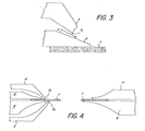
- FIG. 3 is an enlarged view of a portion of the structure shown in Fig. 2.
- Fig. 3 is an enlarged view of a portion of the structure shown in Fig. 2.
- air A leaves the upper orifice 0 1 , moving air molecules collide with stationary air molecules in the region immediately outside the orifice 0 1 , These collisions impart momentum to the stationary molecules and entrain them in the air flow.
- a zone of decreased pressure evolves, which air molecules from both sides of the stream move to equalize.
- pressure equalization is more readily effected in the region above the stream than the region below the stream, because no wall exists in that upper region.
- the region below the stream is therefore of lesser pressure and this causes the stream to attach to the outer surface of film support member 6.
- the inner surface of plate 4 is terminated upstream of the terminus of the outer surface of film support member 6 to effect Coanda attachment to the outer surface of film support member 6 prior to engagement with the film F.
- film support member 6 is tapered from the orifice 0, to the film F to direct the already attached air stream into attachment with the upper surface of the film F. It is believed that this is effective because it reduces turbulence at the terminus of the outer surface of film support member 6. Air flow thus proceeds uninterrupted across the surface of the film F and in close relation thereto. The intimate relation of moving air molecules to the film surface facilitates excellent heat transfer from the film F to the air and very effective film cooling is achieved.
- orifices O2 are of greater dimension than orifices 0, and that the thickness t 2 of the air outlet conduits C is larger than thickness t 1 of the air supply conduit C. This arrangement has been found desirable to maintain stable air flow because the entrainment of air molecules increases the volume of air in the stream and decreases stream velocity somewhat.
- transducer means 11 (only one of which is shown in Fig. 2) are actuated to open film support members 6 and 8 and 7 and 9 respectively.
- Film F is advanced to position an image portion to be projected in the exposure plane.
- air flow is directed to orifices O 1 from a pressurized source (not shown), through the inlet conduits C defined by plates 4 and 5, and film support members 6 and 8.
- This flow moves into Coanda effect attachment with the upper and lower surface of film F at the projection zone by virtue of the orifice configuration described above and thus effectively cools the film F.
- the cooling air then enters orifices O2 and is discharged from the projection apparatus by the passages formed by plates 4 and 5 and film support members 7 and 9.
- a film gate substantially the same as that shown in Figs. 1 and 2 was constructed of dimensions suitable for the projection printing from negatives of 110 size still camera film.
- the projection apertures defined by plates 4 and 5 were approximately 0.5 inches (12.7 mm) by 0.65 inches (16.5 mm) and the air entrance orifices 0 1 were approximately 0.010 to 0.015 inches (0.25 to 0.38 mm) in thickness.
- an air pressure source in the range of about 3.5 to 10.1 Ibs/in 2 gauge (24.1 to 69.6 kPa)
- the film could be maintained in the gate without damage at the varying levels of illumination suitable for print exposure with such film. Such illumination could be maintained well beyond the necessary exposure period; however, if the air was turned off, the film smoked and bubbled within a few seconds.
- Figure 4 shows an alternative preferred embodiment of film gate according to the present invention in which corresponding parts bear the same numerical designation as in Figures 1 and 2. It will be noted that in Figure 4 the exit orifices are defined only by members 7' and 9'.
- the film to be cooled need not be in strip or disc form as shown but could be in other forms e.g., sheet form, such as microfiche or slide.
Landscapes
- Physics & Mathematics (AREA)
- General Physics & Mathematics (AREA)
- Light Sources And Details Of Projection-Printing Devices (AREA)
- Projection Apparatus (AREA)
- Exposure Or Original Feeding In Electrophotography (AREA)
- Holders For Sensitive Materials And Originals (AREA)
Description
- The present invention relates to a film projection gate having a filmcooling structure, for use in projection apparatus such as, for example, a photographic printer.
- In projection printers, especially high speed printers, high intensity radiation from the projection light source heats the film and projection gate structure. This can cause film buckling, and, in severe cases, damage to the film.
- U.S. patent 1,684,304 and Austrian patent 97,271 show high velocity air nozzles having generally elongated orifices directed at a low angle to the film. However, such low angle nozzles do not remove heated air directly adjacent the film surface. Air from nozzles aimed at a higher angle remove the heated air next to the film but its flow is turbulent and is inefficiently removed when heated. Turbulence can also be caused by irregular structure in the air stream including, for example, portions of the film gate.
- An alternative cooling approach is to utilize air directing structure that is light-transparent and thus can be located in the optical projection path, near the film plane.
- Although such structures transmit light, they absorb other wavelengths of the radiation emitted by the projection source and thereby add to the heat load in the projection zone. Further, such light-transparent structures must be reasonably near the film plane to achieve reasonable cooling efficiency; and, in such closely-spaced location, the dirt or scratches which accumulate on the light-transparent structures are within the depth of focus of the projection lens and cause degradation of the projected image.
- It is the object of the invention to provide a film projection gate having air supply means which efficiently cools film under high heat load conditions.
- This object is accomplished by an air supply means which includes a first member having first and second surfaces. The second surface is inclined relative to the film and cooperates with the termination of a third surface to form an elongate orifice as in prior art air nozzles. However, unlike the prior art, the first surface is clampable during projection against the film and the second surface intersects the first surface terminating both surfaces to form the edge of the film gate and to guide the cooling air into Coanda effect attachment with the film.
- This structure efficiently cools the film. It is believed that such efficient cooling is caused by the Coanda effect attachment between the moving air and the film which provides intimacy of the moving air molecules to the film surface which, in turn, facilitates excellent heat transfer from the film to the air. This is accomplished with a minimum of turbulence and without the need, and disadvantages of, light transparent guides.
- According to a preferred embodiment of the invention, there is provided a second member which is part of a similar air supply means for the opposite surface of the film.
- According to a further preferred embodiment, third and fourth members are provided for clamping the margins of the film opposite those respectively clamped by the first and second members and such members also have surfaces inclined relative to the film.
- According to a further preferred embodiment said surfaces of the third and fourth members cooperate with seventh and eighth surfaces respectively to form orifices for receiving air leaving the projection zone.
- In the subsequent description of preferred embodiments of the present invention, reference is made to the attached drawings which form a part hereof and in which:
- Fig. 1 is a top view of the film gate portion of projection apparatus incorporating one embodiment of the present invention;
- Fig. 2 is a view of the film projection gate shown in Fig. 1 taken along section line 2-2;
- Fig. 3 is an enlarged view of a portion of Fig. 2;and
- Fig. 4 is a sectional view similar to Fig. 2, but of an alternative embodiment of film projection gate according to the present invention.
- Referring to Figs. 1 and 2 it can be seen that the film gate 1 comprises apertured upper and
lower mask plates plates - A strip of film F, containing images to be projected, is fed by transport means (not shown) to position successive images in the projection zone. The inner surfaces of
plates plates - Mounted within the air passages are
film support members opposite ends film support members film support members film support members film support members - As shown most clearly in Fig. 2,
outer surfaces film support members inner surfaces plates plate 4 andfilm support member 6 form an inlet conduit C of thickness t1 which delivers cooling air through anorifice 01 to a location along one margin of the film F and such surfaces ofplate 4 andfilm support member 7 form an outlet conduit C of thickness t2 which has an orifice O2 along the opposite margin of the film F. The surfaces ofplate 5 andfilm support member 8 andplate 5 andfilm support member 9 form similar air inlet and outlet conduits C andorifices 01 and O2. - In accordance with the present invention, the surfaces of the
plates film support members lower orifices 01, are predeterminedly configured and located to cause Coanda effect flow of cooling air across the upper and lower surfaces of film F in the projection zone. In general, Coanda effect flow results when a fluid flow passes from a region in which the constraining walls do not diverge substantially, to a region where the walls do diverge substantially. - This phenomenon can be understood more clearly by referring to Fig. 3, which is an enlarged view of a portion of the structure shown in Fig. 2. As air A leaves the
upper orifice 01, moving air molecules collide with stationary air molecules in the region immediately outside theorifice 01, These collisions impart momentum to the stationary molecules and entrain them in the air flow. Since the entrained molecules move with the exiting air stream, a zone of decreased pressure evolves, which air molecules from both sides of the stream move to equalize. However, pressure equalization is more readily effected in the region above the stream than the region below the stream, because no wall exists in that upper region. The region below the stream is therefore of lesser pressure and this causes the stream to attach to the outer surface offilm support member 6. The inner surface ofplate 4 is terminated upstream of the terminus of the outer surface offilm support member 6 to effect Coanda attachment to the outer surface offilm support member 6 prior to engagement with the film F. As shown,film support member 6 is tapered from theorifice 0, to the film F to direct the already attached air stream into attachment with the upper surface of the film F. It is believed that this is effective because it reduces turbulence at the terminus of the outer surface offilm support member 6. Air flow thus proceeds uninterrupted across the surface of the film F and in close relation thereto. The intimate relation of moving air molecules to the film surface facilitates excellent heat transfer from the film F to the air and very effective film cooling is achieved. - Referring back to Fig. 2, it can be seen that orifices O2 are of greater dimension than
orifices 0, and that the thickness t2 of the air outlet conduits C is larger than thickness t1 of the air supply conduit C. This arrangement has been found desirable to maintain stable air flow because the entrainment of air molecules increases the volume of air in the stream and decreases stream velocity somewhat. - Having now described the structural features of one preferred embodiment of the present invention, the mode of operation will be readily understood. To initiate an image projection sequence, transducer means 11 (only one of which is shown in Fig. 2) are actuated to open
film support members plates film support members plates film support members - A film gate substantially the same as that shown in Figs. 1 and 2 was constructed of dimensions suitable for the projection printing from negatives of 110 size still camera film. The projection apertures defined by
plates air entrance orifices 01 were approximately 0.010 to 0.015 inches (0.25 to 0.38 mm) in thickness. With an air pressure source in the range of about 3.5 to 10.1 Ibs/in2 gauge (24.1 to 69.6 kPa), the film could be maintained in the gate without damage at the varying levels of illumination suitable for print exposure with such film. Such illumination could be maintained well beyond the necessary exposure period; however, if the air was turned off, the film smoked and bubbled within a few seconds. It was observed that during application of air pressure, the air motion near the projection zone (and either above or below the film) is directed toward the film, not away from the film as might be expected in a gate not using this cooling means. It was also found that blocking the projection apertures with glass plates, so as to form closed channels for the air flow, drastically reduced the effectiveness of the air cooling and resulted in film buckling and film damage. It was also found that if large air jets, necessarily spaced from the projection apertures because of the presence of optical components on both sides of the film, were substituted for the configuration described above, film cooling was generally ineffective. - It will be appreciated that this result can be attained by various structures different from those described above. For example, Figure 4 shows an alternative preferred embodiment of film gate according to the present invention in which corresponding parts bear the same numerical designation as in Figures 1 and 2. It will be noted that in Figure 4 the exit orifices are defined only by members 7' and 9'.
- Also it will be appreciated that flow of air across the upper and lower surfaces need not be in the same direction. Thus in certain applications the upper and lower air streams could be opposite, orthogonal or otherwise angularly disposed. Also in certain applications flow across only one surface might provide sufficient cooling.
- Of course, the film to be cooled need not be in strip or disc form as shown but could be in other forms e.g., sheet form, such as microfiche or slide.
Claims (4)
Applications Claiming Priority (2)
| Application Number | Priority Date | Filing Date | Title |
|---|---|---|---|
| US06/021,757 US4257695A (en) | 1979-03-19 | 1979-03-19 | Film projection gate |
| US21757 | 2001-12-12 |
Publications (2)
| Publication Number | Publication Date |
|---|---|
| EP0017385A1 EP0017385A1 (en) | 1980-10-15 |
| EP0017385B1 true EP0017385B1 (en) | 1983-05-11 |
Family
ID=21805981
Family Applications (1)
| Application Number | Title | Priority Date | Filing Date |
|---|---|---|---|
| EP80300836A Expired EP0017385B1 (en) | 1979-03-19 | 1980-03-19 | Film projection gate |
Country Status (4)
| Country | Link |
|---|---|
| US (1) | US4257695A (en) |
| EP (1) | EP0017385B1 (en) |
| JP (1) | JPS55126265A (en) |
| DE (1) | DE3063034D1 (en) |
Families Citing this family (10)
| Publication number | Priority date | Publication date | Assignee | Title |
|---|---|---|---|---|
| US4445769A (en) * | 1982-09-30 | 1984-05-01 | Oscar Fisher | Apparatus for processing film discs |
| US4904079A (en) * | 1986-08-13 | 1990-02-27 | Sharp Kabushiki Kaisha | Liquid crystal display device for overhead projector |
| JPH01162378U (en) * | 1988-04-28 | 1989-11-13 | ||
| GB2218668A (en) * | 1988-05-17 | 1989-11-22 | Courtaulds Films & Packaging L | Multilayer polymeric films |
| EP0375425A3 (en) * | 1988-12-22 | 1991-09-18 | Seiko Instruments Inc. | Projection pad incorporating a liquid crystal panel |
| DE4130564A1 (en) * | 1991-09-13 | 1993-03-18 | Agfa Gevaert Ag | Copier for photographic film - has pair of masking plates to hold film flat whilst being copied |
| EP0620121A3 (en) | 1993-04-15 | 1995-11-15 | Minnesota Mining & Mfg | Legume starch stilting material for carbonless papers used in offset printing presses and in copier/duplicators. |
| US5392081A (en) * | 1993-09-29 | 1995-02-21 | Texas Instruments Incorporated | Calculator projection display |
| DE4427003C2 (en) * | 1994-07-29 | 1997-02-06 | Agfa Gevaert Ag | Device and method for guiding photographic films |
| US5959723A (en) * | 1996-10-28 | 1999-09-28 | Eastman Kodak Company | Apparatus for cleaning a transparent cover of a virtual contact color film scanner |
Citations (2)
| Publication number | Priority date | Publication date | Assignee | Title |
|---|---|---|---|---|
| AT97271B (en) * | 1923-09-06 | 1924-06-25 | Ernst Oeser | Cooling device for films. |
| US1684304A (en) * | 1927-09-02 | 1928-09-11 | Boris J Berg | Cooling and fire-prevention apparatus for motion-picture projectors |
Family Cites Families (11)
| Publication number | Priority date | Publication date | Assignee | Title |
|---|---|---|---|---|
| DE344667C (en) * | ||||
| DE550667C (en) * | 1932-05-13 | Bauer Eugen Gmbh | Cooling device for cinema projection machines | |
| US1408203A (en) * | 1919-05-19 | 1922-02-28 | Jenkins Charles Francis | Cooling device for motion-picture machines |
| DE425307C (en) * | 1924-11-15 | 1926-02-15 | Anciens Etablissements Pathe F | Air cooling device on the picture window of projection apparatus |
| US2315914A (en) * | 1940-09-26 | 1943-04-06 | Eastman Kodak Co | Film gate for projectors |
| DE892551C (en) * | 1950-11-28 | 1953-10-08 | Bauer Eugen Gmbh | Film projector with air-cooled film web and film door |
| DE1237356B (en) * | 1961-07-26 | 1967-03-23 | Erich Zillmer | Image projector with cooling fan |
| US3179007A (en) * | 1962-03-09 | 1965-04-20 | Bausch & Lomb | Slide projector with radiation pre-heating of slides |
| DE2450417A1 (en) * | 1974-10-23 | 1976-04-29 | Agfa Gevaert Ag | Gate for support of photographic material during projection - has cooling air channel with nozzles directed onto the slide held within |
| JPS52119822U (en) * | 1976-03-09 | 1977-09-10 | ||
| AT387759B (en) * | 1987-04-15 | 1989-03-10 | Mayer Rudolf | CONTAINER FOR BIOLOGICAL SUBSTANCES, IN PARTICULAR FOODSTUFFS |
-
1979
- 1979-03-19 US US06/021,757 patent/US4257695A/en not_active Expired - Lifetime
-
1980
- 1980-03-19 JP JP3574480A patent/JPS55126265A/en active Granted
- 1980-03-19 EP EP80300836A patent/EP0017385B1/en not_active Expired
- 1980-03-19 DE DE8080300836T patent/DE3063034D1/en not_active Expired
Patent Citations (2)
| Publication number | Priority date | Publication date | Assignee | Title |
|---|---|---|---|---|
| AT97271B (en) * | 1923-09-06 | 1924-06-25 | Ernst Oeser | Cooling device for films. |
| US1684304A (en) * | 1927-09-02 | 1928-09-11 | Boris J Berg | Cooling and fire-prevention apparatus for motion-picture projectors |
Also Published As
| Publication number | Publication date |
|---|---|
| EP0017385A1 (en) | 1980-10-15 |
| JPS55126265A (en) | 1980-09-29 |
| DE3063034D1 (en) | 1983-06-16 |
| US4257695A (en) | 1981-03-24 |
| JPH0228854B2 (en) | 1990-06-26 |
Similar Documents
| Publication | Publication Date | Title |
|---|---|---|
| EP0017385B1 (en) | Film projection gate | |
| US4959693A (en) | Duplex reproducing apparatus with device for cooling and conveying fused toner image | |
| US6909864B2 (en) | Image forming apparatus configuring air passage and process cartridge for the apparatus | |
| US20100208151A1 (en) | Cooling device for electronic apparatus and liquid crystal projector | |
| US2315914A (en) | Film gate for projectors | |
| KR920018519A (en) | Fog screen forming method and apparatus and image forming method using same | |
| JP4030208B2 (en) | Projection display | |
| JP2704982B2 (en) | Method and apparatus for preventing backflow in air or gas cooled lamps | |
| US3792919A (en) | Motion picture film system with multi-purpose film cassette | |
| US3748033A (en) | Device for locating a film transparency | |
| US3273953A (en) | Motion picture projector film focus stabilization and lens cooling means | |
| US3610747A (en) | Cartridge-loaded film strip projector, particularly for narrow film | |
| US2817267A (en) | Film cooling apparatus for film projectors | |
| US2443171A (en) | Photographic film gate for projectors | |
| GB1312503A (en) | Liquid film gate for an optical printer | |
| US3598486A (en) | Drying device for electro photographic copying machines | |
| US3457007A (en) | Differential pressure gate | |
| US2943534A (en) | Film projector device | |
| US3450474A (en) | Record copier | |
| JPS56102392A (en) | Laser working optical device | |
| JP3192254B2 (en) | Improved receiving member cooling system for duplication machines | |
| US3767293A (en) | Unique prismatic element and mounting arrangement therefor | |
| GB2282463A (en) | Cleaning photographic film | |
| US5668625A (en) | Apparatus for and method for handling film in a photographic printer | |
| GB2032646A (en) | Film holding device |
Legal Events
| Date | Code | Title | Description |
|---|---|---|---|
| PUAI | Public reference made under article 153(3) epc to a published international application that has entered the european phase |
Free format text: ORIGINAL CODE: 0009012 |
|
| AK | Designated contracting states |
Designated state(s): CH DE FR GB |
|
| DET | De: translation of patent claims | ||
| 17P | Request for examination filed |
Effective date: 19810310 |
|
| GRAA | (expected) grant |
Free format text: ORIGINAL CODE: 0009210 |
|
| AK | Designated contracting states |
Designated state(s): CH DE FR GB |
|
| REF | Corresponds to: |
Ref document number: 3063034 Country of ref document: DE Date of ref document: 19830616 |
|
| ET | Fr: translation filed | ||
| PLBE | No opposition filed within time limit |
Free format text: ORIGINAL CODE: 0009261 |
|
| STAA | Information on the status of an ep patent application or granted ep patent |
Free format text: STATUS: NO OPPOSITION FILED WITHIN TIME LIMIT |
|
| 26N | No opposition filed | ||
| PGFP | Annual fee paid to national office [announced via postgrant information from national office to epo] |
Ref country code: GB Payment date: 19960208 Year of fee payment: 17 |
|
| PGFP | Annual fee paid to national office [announced via postgrant information from national office to epo] |
Ref country code: FR Payment date: 19960307 Year of fee payment: 17 |
|
| PGFP | Annual fee paid to national office [announced via postgrant information from national office to epo] |
Ref country code: DE Payment date: 19960328 Year of fee payment: 17 |
|
| PGFP | Annual fee paid to national office [announced via postgrant information from national office to epo] |
Ref country code: CH Payment date: 19960423 Year of fee payment: 17 |
|
| PG25 | Lapsed in a contracting state [announced via postgrant information from national office to epo] |
Ref country code: GB Effective date: 19970319 |
|
| PG25 | Lapsed in a contracting state [announced via postgrant information from national office to epo] |
Ref country code: CH Effective date: 19970331 |
|
| GBPC | Gb: european patent ceased through non-payment of renewal fee |
Effective date: 19970319 |
|
| REG | Reference to a national code |
Ref country code: CH Ref legal event code: PL |
|
| PG25 | Lapsed in a contracting state [announced via postgrant information from national office to epo] |
Ref country code: FR Free format text: LAPSE BECAUSE OF NON-PAYMENT OF DUE FEES Effective date: 19971128 |
|
| PG25 | Lapsed in a contracting state [announced via postgrant information from national office to epo] |
Ref country code: DE Effective date: 19971202 |
|
| REG | Reference to a national code |
Ref country code: FR Ref legal event code: ST |