EP0017347B1 - An improved hanger design for a swinging centrifuge rotor - Google Patents
An improved hanger design for a swinging centrifuge rotor Download PDFInfo
- Publication number
- EP0017347B1 EP0017347B1 EP80300674A EP80300674A EP0017347B1 EP 0017347 B1 EP0017347 B1 EP 0017347B1 EP 80300674 A EP80300674 A EP 80300674A EP 80300674 A EP80300674 A EP 80300674A EP 0017347 B1 EP0017347 B1 EP 0017347B1
- Authority
- EP
- European Patent Office
- Prior art keywords
- rotor
- guide sleeve
- hanger
- hanger member
- bucket
- Prior art date
- Legal status (The legal status is an assumption and is not a legal conclusion. Google has not performed a legal analysis and makes no representation as to the accuracy of the status listed.)
- Expired
Links
- 230000002093 peripheral effect Effects 0.000 claims 1
- 239000000126 substance Substances 0.000 description 3
- 230000001133 acceleration Effects 0.000 description 1
- 230000006835 compression Effects 0.000 description 1
- 238000007906 compression Methods 0.000 description 1
- 238000010276 construction Methods 0.000 description 1
Images


Classifications
-
- B—PERFORMING OPERATIONS; TRANSPORTING
- B04—CENTRIFUGAL APPARATUS OR MACHINES FOR CARRYING-OUT PHYSICAL OR CHEMICAL PROCESSES
- B04B—CENTRIFUGES
- B04B5/00—Other centrifuges
- B04B5/04—Radial chamber apparatus for separating predominantly liquid mixtures, e.g. butyrometers
- B04B5/0407—Radial chamber apparatus for separating predominantly liquid mixtures, e.g. butyrometers for liquids contained in receptacles
- B04B5/0414—Radial chamber apparatus for separating predominantly liquid mixtures, e.g. butyrometers for liquids contained in receptacles comprising test tubes
- B04B5/0421—Radial chamber apparatus for separating predominantly liquid mixtures, e.g. butyrometers for liquids contained in receptacles comprising test tubes pivotably mounted
Definitions
- This invention relates generally to a centrifuge apparatus and more particularly to ultra- centrifuges which utilize high rotational speeds.
- Swinging bucket type centrifuges include buckets, which contain the substance to be centrifuged and are supported from a rotor body by suitable supporting means. While the rotor is at rest, the bucket is generally hanging vertically downward from an appropriate bucket hanger member, and during acceleration and deceleration the buckets swing up to and down from a horizontal plane: They are restrained from outward radial movement under the high centrifugal forces by shoulder portions of the rotor which supports the buckets.
- U.S. Patent No. 3,393,864 discloses a centrifuge assembly in which each bucket is supported by an independent bucket- hanger member which is spring biased toward the rotational axis of the rotor. This permits the bucket to seat in a cavity of the rotor during operation of the centrifuge. It has been discovered that under certain conditions it is possible for the rotor bucket and hanger member to twist or turn during operation. This can cause the bucket contents to mix when the centrifuge decelerates and the bucket returns to its vertical position.
- U.S. Patent No. 3,935,995, Williams et al. provides a spring biasing means similar to the means utilized by Galasso et al.
- the Williams arrangement also includes a bucket hanger which supports the centrifuge buckets, a compression spring and a screw which is secured in the body of the rotor.
- the hanger member is capable of movement in a radial direction of the rotor and is biased inwardly by the spring toward the axis of rotation of the rotor similarly as in the -Galasso arrangement.
- the hanger member is designed to have a slidable fit within a recess formed in the rotor body itself.
- the hanger member is "generally square or rectangular" while the recess "also has a square or rectangular cross section to prevent the hanger from rotating about its path of movement" as it slides within the recess formed in the rotor.
- the present invention is an improved hanger design for a swinging bucket centrifuge rotor characterized in that the hanger member is supported solely by means of a non-circular opening in the hanger member which bears on the guide sleeve to permit the hanger member to slide radially on the guide sleeve but prevents rotation thereof with respect to the guide sleeve, and fastening means attached to the rotor through the guide sleeve for supporting the guide sleeve and hanger within the cavity.
- the mounting arrangement for the hanger according to the invention provides an improvement on the prior art in that it operates with less friction and since the hanger does not engage a receptacle there is no constraint on its radial play. This permits the hanger to have a looser fit with the sleeve and it is thus cheaper to make, generates less friction and is more likely to provide a smooth operation.
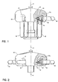
- the centrifuge rotor 10 illustrated in Figure 1 is driven by a motor (not shown) about a vertical axis 11.
- Figure 1 illustrates the rotor in a rest position.
- buckets 12 which contain the substance to be centrifuged.
- buckets 12 include bucket extensions 12a with pin members 14.
- Cavities 17 of the rotor allow buckets to pivot into horizontal positions as shown by the dashed line in Figure 1, and illustrated in Figure 2, during rotation of rotor 10. Shoulder portions 17a of cavities 17 are formed in the body of rotor 10, allowing seat portions 16 of buckets 12 to properly seat within rotor 10 and to limit outward radial movement of buckets 12.
- FIG 3 pins 14 are received in cross-drilled holes in bucket extensions 12a in a first embodiment of the invention.
- Figure 4 illustrates a second embodiment of the invention, showing pin 14 received in a cross-drilled hole of hanger member 18.
- Each cavity 17 is provided with a hanger device which includes a fastener means 19, guide sleeve 21, hanger member 18, and spring means 22.
- Sleeve 21 surrounds fastener 19 and abuts flanged end 20.
- Spring 22 is situated around sleeve 21 and is confined within the interior of hanger member 18.
- Each hanger member 18 is slidably mounted in rotor 10 by fastener 19 and guide sleeve 21 as illustrated in Figures 3 and 4.
- Each hanger member 18 supports a bucket 12 and is slidable in a radial direction with reference to vertical axis 11.
- Fastener 19 is preferably in the nature of a threaded screw or bolt member with a first end threaded and secured to the body of rotor 10, and a flanged second end 20.
- buckets 12 are filled with the substances to be centrifuged, capped and hung on hanger members 18.
- Rotation of rotor 10 swings buckets 12 from vertical positions to horizontal positions and the centrifugal force provided by the rotating buckets 12 begins to cancel the biasing force exerted radially inward by the spring 22 against hanger 18, allowing buckets 12 to seat against shoulder portion 17a. After sufficient centrifuging, the reverse occurs and buckets 12 return to vertical positions.
- Sleeve 21 is mounted in recess 23 formed in rotor body 10 within cavity 17.
- the geometric configuration of aperture 23 is non-circular in shape, such as square or rectangular.
- the exterior surface of sleeve 21 is also non-circular and, in the preferred embodiments, conforms to the shape of recess 23.
- Cooperation between the respective non-circular shapes of recess 23 and sleeve 21 prevents rotational movement of sleeve 21 with respect to the longitudinal axis 25 of fastener 19.
- a portion of the hanger member 18 is slidably supported on sleeve 21, and is, in the preferred embodiment of the invention, of the same geometric configuration as the exterior surface of sleeve 21. In this manner, radial movement of hanger member 18 is guided along sleeve 21 and rotational movement with respect to axis 25 is prevented.
- Figure 5 illustrates a cross-sectional view of rotor 10, recess 23, sleeve 21 and fastener 19, taken along the line 5-5 in Figure 3.
- Figure 5 shows the body of fastener 19 having a circular cross-sectional shape.
- the interior of sleeve 21 also has a circular cross-sectional shape.
- the exterior of sleeve 21 has an essentially square shape, and recess 23 also has an essentially square shape.
- the cross-sectional shapes of recess 23 and the exterior of sleeve 21 are non-circular to prevent rotational movement of sleeve 21 about axis 25. It will be understood that other non-circular shapes may be employed so long as the shape of the recess mates closely with that of the sleeve to prevent rotational movement of the sleeve about axis 25.
- Figure 6 illustrates a cross-sectional view of fastener 19, sleeve 21 and hanger member 18, taken along the line 6-6 in Figure 3.
- Figure 6 shows fastener 19 and the interior of sleeve 21 both having circular cross-sectional shapes, the exterior of sleeve 21 having an essentially square shape, and the opening or interior portion 27 of hanger member 18 engaged with the exterior of sleeve 21 also having an essentially square shape.
- Sleeve 21 guides the radial movement of hanger member 18 so that bucket 12 is properly seated during operation of rotor 10. Should fastener 19 become loose at any time as a result of rotor vibration, the rotational movement of fastener 19 will not be transferred to sleeve 21 since sleeve 21 is nonrotat- able within non-circular recess 23. Because the rotational movement of fastener 19 cannot be transferred to sleeve 21, sleeve 21 does not permit rotational movement from fastener 19 to be transferred to hanger member 18. By this construction, rotational movement of hanger member 18 and bucket 12 about axis 25 is prevented.
Landscapes
- Centrifugal Separators (AREA)
Applications Claiming Priority (2)
| Application Number | Priority Date | Filing Date | Title |
|---|---|---|---|
| US20388 | 1979-03-14 | ||
| US06/020,388 US4190195A (en) | 1979-03-14 | 1979-03-14 | Hanger design for a swinging centrifuge rotor |
Publications (2)
| Publication Number | Publication Date |
|---|---|
| EP0017347A1 EP0017347A1 (en) | 1980-10-15 |
| EP0017347B1 true EP0017347B1 (en) | 1983-09-14 |
Family
ID=21798366
Family Applications (1)
| Application Number | Title | Priority Date | Filing Date |
|---|---|---|---|
| EP80300674A Expired EP0017347B1 (en) | 1979-03-14 | 1980-03-05 | An improved hanger design for a swinging centrifuge rotor |
Country Status (5)
| Country | Link |
|---|---|
| US (1) | US4190195A (show.php) |
| EP (1) | EP0017347B1 (show.php) |
| JP (1) | JPS55133253U (show.php) |
| CA (1) | CA1120903A (show.php) |
| DE (1) | DE3064794D1 (show.php) |
Families Citing this family (8)
| Publication number | Priority date | Publication date | Assignee | Title |
|---|---|---|---|---|
| US4391597A (en) * | 1981-06-29 | 1983-07-05 | Beckman Instruments, Inc. | Hanger for centrifuge buckets |
| US4589864A (en) * | 1984-11-05 | 1986-05-20 | E. I. Du Pont De Nemours And Company | Centrifuge rotor having a resilient trunnion |
| US4624655A (en) * | 1984-12-21 | 1986-11-25 | E. I. Du Pont De Nemours And Company | Restoring cap assembly for a centrifuge rotor having a flexible carrier |
| US4659325A (en) * | 1984-12-21 | 1987-04-21 | E. I. Du Pont De Nemours And Company | Centrifuge rotor having a flexible carrier |
| NL8503149A (nl) * | 1985-11-15 | 1987-06-01 | Ultra Centrifuge Nederland Nv | Centrifuge, in het bijzonder voor biomedische toepassingen. |
| US5496255A (en) | 1994-12-09 | 1996-03-05 | Beckman Instruments, Inc. | Swinging bucket centrifugation rotor with conforming bucket seat |
| US5624370A (en) * | 1995-12-15 | 1997-04-29 | Sorvall Products, L.P. | Bucket for use in a swinging bucket centrifuge rotor |
| US5591114A (en) * | 1995-12-15 | 1997-01-07 | Sorvall Products, L.P. | Swinging bucket centrifuge rotor |
Family Cites Families (4)
| Publication number | Priority date | Publication date | Assignee | Title |
|---|---|---|---|---|
| US3393864A (en) * | 1966-04-11 | 1968-07-23 | Beckman Instruments Inc | Centrifuge apparatus |
| JPS4833059A (show.php) * | 1971-05-19 | 1973-05-07 | ||
| US3997105A (en) * | 1975-04-11 | 1976-12-14 | E. I. Du Pont De Nemours And Company | Swinging bucket centrifuge rotor |
| US3935995A (en) * | 1975-05-07 | 1976-02-03 | E. I. Du Pont De Nemours And Company | Swinging bucket centrifuge rotor |
-
1979
- 1979-03-14 US US06/020,388 patent/US4190195A/en not_active Expired - Lifetime
-
1980
- 1980-02-29 CA CA000346721A patent/CA1120903A/en not_active Expired
- 1980-03-05 DE DE8080300674T patent/DE3064794D1/de not_active Expired
- 1980-03-05 EP EP80300674A patent/EP0017347B1/en not_active Expired
- 1980-03-14 JP JP1980032620U patent/JPS55133253U/ja active Pending
Also Published As
| Publication number | Publication date |
|---|---|
| US4190195A (en) | 1980-02-26 |
| CA1120903A (en) | 1982-03-30 |
| DE3064794D1 (en) | 1983-10-20 |
| EP0017347A1 (en) | 1980-10-15 |
| JPS55133253U (show.php) | 1980-09-20 |
Similar Documents
| Publication | Publication Date | Title |
|---|---|---|
| EP0017347B1 (en) | An improved hanger design for a swinging centrifuge rotor | |
| CN106064121B (zh) | 用于离心机的混合型转子、包括混合型转子和离心机容器的套件以及离心机容器 | |
| US10682616B2 (en) | Centrifuge with exchangeable rotors | |
| US3935995A (en) | Swinging bucket centrifuge rotor | |
| US4375272A (en) | Fixed angle tube carrier | |
| US3393864A (en) | Centrifuge apparatus | |
| EP0181582B1 (en) | Centrifuge rotor having a resilient trunnion | |
| US3687359A (en) | Centrifuge rotor | |
| US3997105A (en) | Swinging bucket centrifuge rotor | |
| US4120450A (en) | High-capacity centrifuge rotor | |
| EP1102639B1 (en) | Centrifuge rotor lock | |
| US4718885A (en) | Swinging bucket centrifuge rotor having an uninterrupted knife edge pivot | |
| US4254905A (en) | Centrifuge rotor construction | |
| US4897075A (en) | Centrifuge drive hub | |
| US5591114A (en) | Swinging bucket centrifuge rotor | |
| US5624370A (en) | Bucket for use in a swinging bucket centrifuge rotor | |
| US3873021A (en) | Wire frame centrifuge | |
| US6183408B1 (en) | Rotor shaft assembly having non-linear stiffness | |
| CN218423417U (zh) | 一种立式试管离心机 | |
| EP0715895B1 (en) | Swinging bucket centrifugation rotor with conforming bucket seat | |
| JPH09155236A (ja) | マイクロプレート用アダプタ | |
| CN220969499U (zh) | 一种离心机转子自锁结构 | |
| JPH08108097A (ja) | 遠心分離機用スイングロータ | |
| JPH07222940A (ja) | 遠心分離機用ロータ | |
| JPS6335797Y2 (show.php) |
Legal Events
| Date | Code | Title | Description |
|---|---|---|---|
| PUAI | Public reference made under article 153(3) epc to a published international application that has entered the european phase |
Free format text: ORIGINAL CODE: 0009012 |
|
| AK | Designated contracting states |
Designated state(s): CH DE FR GB |
|
| 17P | Request for examination filed |
Effective date: 19810408 |
|
| GRAA | (expected) grant |
Free format text: ORIGINAL CODE: 0009210 |
|
| AK | Designated contracting states |
Designated state(s): CH DE FR GB |
|
| REF | Corresponds to: |
Ref document number: 3064794 Country of ref document: DE Date of ref document: 19831020 |
|
| ET | Fr: translation filed | ||
| PLBE | No opposition filed within time limit |
Free format text: ORIGINAL CODE: 0009261 |
|
| STAA | Information on the status of an ep patent application or granted ep patent |
Free format text: STATUS: NO OPPOSITION FILED WITHIN TIME LIMIT |
|
| 26N | No opposition filed | ||
| PGFP | Annual fee paid to national office [announced via postgrant information from national office to epo] |
Ref country code: CH Payment date: 19920327 Year of fee payment: 13 |
|
| PG25 | Lapsed in a contracting state [announced via postgrant information from national office to epo] |
Ref country code: CH Effective date: 19930331 |
|
| REG | Reference to a national code |
Ref country code: CH Ref legal event code: PL |
|
| PGFP | Annual fee paid to national office [announced via postgrant information from national office to epo] |
Ref country code: GB Payment date: 19960208 Year of fee payment: 17 |
|
| PGFP | Annual fee paid to national office [announced via postgrant information from national office to epo] |
Ref country code: FR Payment date: 19960307 Year of fee payment: 17 |
|
| PGFP | Annual fee paid to national office [announced via postgrant information from national office to epo] |
Ref country code: DE Payment date: 19960328 Year of fee payment: 17 |
|
| PG25 | Lapsed in a contracting state [announced via postgrant information from national office to epo] |
Ref country code: GB Effective date: 19970305 |
|
| GBPC | Gb: european patent ceased through non-payment of renewal fee |
Effective date: 19970305 |
|
| PG25 | Lapsed in a contracting state [announced via postgrant information from national office to epo] |
Ref country code: FR Free format text: LAPSE BECAUSE OF NON-PAYMENT OF DUE FEES Effective date: 19971128 |
|
| PG25 | Lapsed in a contracting state [announced via postgrant information from national office to epo] |
Ref country code: DE Effective date: 19971202 |
|
| REG | Reference to a national code |
Ref country code: FR Ref legal event code: ST |