EP0017156B1 - Keramischer Brennerkopf mit zum Brennermund parallel zueinander geführten Strömungskanälen für Brennstoff und Oxidationsmittel - Google Patents
Keramischer Brennerkopf mit zum Brennermund parallel zueinander geführten Strömungskanälen für Brennstoff und Oxidationsmittel Download PDFInfo
- Publication number
- EP0017156B1 EP0017156B1 EP80101597A EP80101597A EP0017156B1 EP 0017156 B1 EP0017156 B1 EP 0017156B1 EP 80101597 A EP80101597 A EP 80101597A EP 80101597 A EP80101597 A EP 80101597A EP 0017156 B1 EP0017156 B1 EP 0017156B1
- Authority
- EP
- European Patent Office
- Prior art keywords
- fuel
- burner
- flow ducts
- mouth
- burner head
- Prior art date
- Legal status (The legal status is an assumption and is not a legal conclusion. Google has not performed a legal analysis and makes no representation as to the accuracy of the status listed.)
- Expired
Links
Images




Classifications
-
- F—MECHANICAL ENGINEERING; LIGHTING; HEATING; WEAPONS; BLASTING
- F23—COMBUSTION APPARATUS; COMBUSTION PROCESSES
- F23L—SUPPLYING AIR OR NON-COMBUSTIBLE LIQUIDS OR GASES TO COMBUSTION APPARATUS IN GENERAL ; VALVES OR DAMPERS SPECIALLY ADAPTED FOR CONTROLLING AIR SUPPLY OR DRAUGHT IN COMBUSTION APPARATUS; INDUCING DRAUGHT IN COMBUSTION APPARATUS; TOPS FOR CHIMNEYS OR VENTILATING SHAFTS; TERMINALS FOR FLUES
- F23L15/00—Heating of air supplied for combustion
- F23L15/04—Arrangements of recuperators
-
- F—MECHANICAL ENGINEERING; LIGHTING; HEATING; WEAPONS; BLASTING
- F23—COMBUSTION APPARATUS; COMBUSTION PROCESSES
- F23D—BURNERS
- F23D3/00—Burners using capillary action
- F23D3/40—Burners using capillary action the capillary action taking place in one or more rigid porous bodies
-
- Y—GENERAL TAGGING OF NEW TECHNOLOGICAL DEVELOPMENTS; GENERAL TAGGING OF CROSS-SECTIONAL TECHNOLOGIES SPANNING OVER SEVERAL SECTIONS OF THE IPC; TECHNICAL SUBJECTS COVERED BY FORMER USPC CROSS-REFERENCE ART COLLECTIONS [XRACs] AND DIGESTS
- Y02—TECHNOLOGIES OR APPLICATIONS FOR MITIGATION OR ADAPTATION AGAINST CLIMATE CHANGE
- Y02E—REDUCTION OF GREENHOUSE GAS [GHG] EMISSIONS, RELATED TO ENERGY GENERATION, TRANSMISSION OR DISTRIBUTION
- Y02E20/00—Combustion technologies with mitigation potential
- Y02E20/34—Indirect CO2mitigation, i.e. by acting on non CO2directly related matters of the process, e.g. pre-heating or heat recovery
Definitions
- the invention relates to a ceramic burner head with flow channels for fuel and oxidizing agent running parallel to the burner mouth, with partition walls serving for heat exchange between oxidizing agent and fuel being provided between adjacent flow channels.
- the ceramic burner head can be used in industrial furnaces, but is also intended for heat generators with a lower output.
- EP-A1-0012308 (this document falls under Article 54 (3)) describes a burner head with which gaseous but also liquid fuels can be burned, provided the preheating of the oxidizing agent causes the liquid fuel to heat exchange within the flow channels leading to the fuel heated with the oxidizing agent and evaporated before exiting the burner mouth.
- a gasification burner for liquid fuels, a gasification burner is known from DE-A-2 129 663, which has a gasification body made of porous, heat-resistant material and devices for supplying the liquid fuel via the gasification body to a combustion chamber.
- Combustion air flows around the walls of the gasification body in the form of a hollow cylinder, with some of the fuel already burning at least in the interior of the hollow cylinder after ignition of the fuel-air mixture formed.
- the associated considerable heating of the gasification body favors the above-mentioned mercury processes in the fuel to an increased extent. There is therefore a risk that the porous gasification body will clog relatively quickly with residues.
- the object of the invention is to provide a burner suitable for the combustion of liquid fuels, which allows the fuel to be mixed with the combustion air at a lower temperature than the combustion air and to produce a low-pollutant, ignitable mixture without causing Overheating the liquid fuel cracking of the fuel occurs.
- the partition walls between the flow channels then consist of a material that is permeable to the fuel.
- porous ceramics such as silicon carbide or silicon nitrite, or sintered metal, which is known as a filter material, are used as materials.
- the fuel flow channels are closed to the combustion chamber.
- the liquid fuel advantageously penetrates the porous material and evaporates on the surface of the partition walls facing the oxidant stream. Oxidizing agent and fuel gas thus mix before reaching the burner mouth, the porous partition walls leading to film evaporation of the fuel, which avoids the formation of droplets.
- the flow channels for the fuel are closed by means of porous material mouthpieces protruding from the burner mouth.
- an ignition device extending transversely to the flow channels is arranged on the burner mouth, the features of which are specified in patent claim 3.
- the ignition device has an evaporation body for the liquid fuel which projects above the burner mouth and in which a cavity is provided for the evaporation of the fuel and is open towards the combustion chamber and is traversed by an electrically heatable ignition wire.
- the evaporating fuel can be ignited in the cavity, with pilot flames which ignite the fuel-oxidant mixture flowing out of the burner mouth ignite via branch channels which lead to the mouths of the flow channels. The mixture ignites simultaneously across the entire width of the burner mouth.
- a further embodiment of the invention consists in arranging the burner heads in pairs in mirror image to one another and in such a way that one burner mouth lies next to the other. In this way, high-performance burners can also be created while maintaining low-cost components.
- the burner pairs expediently form rows arranged one behind the other, the desired heating output determining the required number of burner pairs.
- the burner heads are preferably arranged in the manner of the walls of the honeycomb.
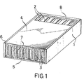
- the burner head consists of a ceramic stone 1 with flow channels 2, 3, which are covered in their entire length by cover walls 4, 5.
- the flow channels 2, 3 have an elongated cross section and, in the exemplary embodiments, are designed as rectangularly shaped, more than 1 mm wide slots running in the stone 1 in a straight line.
- the flow channels are guided parallel to one another to the burner mouth 6 and are arranged in pairs offset from one another, a partition 7 being formed in each case between adjacent flow channels.
- the wall thickness of the partition 7 can be reduced to about 0.4 mm.
- Inflow openings for the flow channels 2, 3 are created by depositing the top wall 4, 5.
- the cover walls are set down so far that the flow channels projecting beyond the adjacent flow channels towards the cover wall to be removed are opened.
- inflow openings are arranged in this way on the side surface of the burner head which is concealed in the perspective illustration.
- the flow channels 2, 3 are closed on the end 8 of the burner head opposite the burner mouth 6. Liquid fuel is introduced into the burner head in the flow channels 2, and air flows as an oxidizing agent in the flow channels 3.
- the flow channels 2 are closed at the burner mouth 6 towards the combustion chamber.
- the partition walls 7 of the burner head consist of a porous material which is permeable to the liquid fuel carried in the flow channels 2. Liquid fuel evaporates on the surface of the partition walls facing the flow channels 3 and mixes with the air guided in the flow channels 3. The air is preheated and has a temperature at which an amount of fuel suitable for the formation of an ignitable fuel-air mixture evaporates. If heating oils are used as fuels, it is advisable to heat the air to around 200 ° C. The evaporation of the liquid fuel on the partition wall surface also prevents overheating of the liquid fuel in the flow channels 2 as a result of evaporative cooling taking effect.
- a recuperator which is preceded by the burner head and through which a heating medium flows, is used to preheat the air sucked in as an oxidizing agent by a fan (not shown separately in the drawing). After the burner head has been started up, waste gas flowing out of the combustion chamber is preferably used as the heating medium.
- the flow channels 2 for fuel to the combustion chamber are closed by means of mouthpieces 9 which protrude beyond the burner mouth 6.
- the mouthpieces 9 also consist of porous, fuel-permeable material.
- a fuel film forms on the surface of the mouthpieces and evaporates into the preheated combustion air.
- an ignition device is arranged which extends over all flow channels 2, 3 and which has an evaporation body 10 which is arranged at the end of a supply line 11 for fuel.
- a cavity 12 is provided in the evaporation body 10 and is traversed by an electrically heatable ignition wire 13 (FIG. 3).
- the ignition wire can be connected to a current source which is not shown separately in FIG. 3.
- the fuel penetrating the evaporation body 10 evaporates into the cavity and is ignited by heating to the ignition temperature by means of the ignition wire.
- the ignition flames that are produced are led via branch channels 14 to the mouths of the flow channels and ignite the fuel-air mixture emerging from the flow channels in a homogenization zone formed in front of the burner mouth. After the combustion of the mixture flowing out of the flow channels 3 has commenced, the current source applied to the ignition wire is switched off again.
- branch channels 14 are provided on the evaporation body 10 on both side surfaces, so that combustion occurs on the entire surface of the evaporation body after the ignition.
- the shape of the mouthpieces 9 determines the surface that is available for the evaporation of the liquid fuel. Relatively large surfaces have mouthpieces 9a to 9c shown in FIGS. 4 to 6.
- the burner head is suitable for burning different quality heating oil.
- the film evaporation of the liquid fuel also allows the use of heavy heating oils without causing harmful precipitation or residues in the combustion chamber due to cracking processes.
- the burner output can be changed quickly and easily by relatively small pressure changes for the liquid fuel.
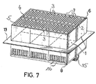
- FIG. 1 A number of burner heads connected in parallel are shown in FIG.
- the ceramic stones 1 are mirror images of one another and are arranged such that one burner mouth 6 lies next to the other.
- the fuel is fed to the burner heads via a feed 15, air flows through openings 16 as the oxidizing agent.
- a recuperator part 17 is connected upstream of the burner head for preheating the combustion air introduced into the burner head.
- the heating medium that flows out of the combustion chamber is preferably used Exhaust gas.
- the hot exhaust gas flows through the recuperator part 17 in counterflow to the combustion air.
- Fig. 9 several burner heads with recuperator part are arranged in mirror image to each other. The burner pairs form several rows. The number of individual burner pairs is determined by the desired total output of the burner group.
- Gas seals 18 are inserted between the ceramic stones 1 (FIG. 8).
- a holder 19 in the exemplary embodiments according to FIGS. 7 to 9 serves for fastening the burner heads and at the same time also for sealing.
- FIG. 10 shows burner heads arranged like a honeycomb.
- the free spaces 20 remaining between the burner heads are used to lay the supply lines for the fuel or serve as a channel for the supply or discharge of exhaust gas.
- the burner pairs supporting and sealing brackets 21 are inserted.
Landscapes
- Engineering & Computer Science (AREA)
- Chemical & Material Sciences (AREA)
- Combustion & Propulsion (AREA)
- Mechanical Engineering (AREA)
- General Engineering & Computer Science (AREA)
- Spray-Type Burners (AREA)
- Air Supply (AREA)
Description
- Die Erfindung bezieht sich auf einen keramischen Brennerkopf mit zum Brennermund parallel zueinander geführten Strömungskanälen für Brennstoff und Oxidationsmittel, wobei zwischen benachbarten Strömungskanälen einem Wärmeaustausch zwischen Oxidationsmittel und Brennstoff dienende Trennwände vorgesehen sind.
- Der keramische Brennerkopf ist in Industrieöfen einsetzbar, aber auch für Wärmeerzeuger kleinerer Leistung bestimmt. In der EP-A1-0012308 (dieses Dokument fällt unter Artikel 54 Absatz 3) wird ein Brennerkopf beschrieben, mit dem sich gasförmige, aber auch flüssige Brennstoffe verbrennen lassen, soweit durch Vorerhitzen des Oxidationsmittels der flüssige Brennstoff innerhalb der den Brennstoff führenden Strömungskanäle im Wärmeaustausch mit dem Oxidationsmittel erwärmt und vor Austritt aus dem Brennermund verdampft wird. Dabei lässt sich jedoch nicht in allen Fällen vermeiden, dass beim Verdampfen durch Crackprozesse im Brennstoff unerwünschte Rückstücke gebildet werden, die sich in den den Brennstoff führenden Strömungskanälen absetzen oder zu unerwünschten Niederschlägen im Brennraum und vom Abgas durchströmten Räumen führen.
- Für flüssige Brennstoffe ist aus DE-A-2 129 663 ein Vergasungsbrenner bekannt, der einen Vergasungskörper aus porösem, wärmebeständigem Material und Einrichtungen zur Zuführung des flüssigen Brennstoffes über den Vergasungskörper zu einer Brennkammer aufweist. Die Wände des hohlzylinderförmig ausgebildeten Vergasungskörpers werden von Verbrennungsluft umspült, wobei zumindest im Innenraum des Hohlzylinders nach Zündung des gebildeten Brennstoff-Luft-Gemisches bereits ein Teil des Brennstoffes verbrennt. Die damit verbundene erhebliche Aufheizung des Vergasungskörpers begünstigt die oben bereits erwähnten Queckprozesse im Brennstoff in verstärktem Masse. Es besteht somit die Gefahr, dass sich der poröse Vergasungskörper verhältnismässig rasch mit Rückständen zusetzt.
- Aufgabe der Erfindung ist es, einen zur Verbrennung flüssiger Brennstoffe geeigneten Brenner zu schaffen, der es gestattet, den Brennstoff mit einer niedrigeren Temperatur, als sie die Verbrennungsluft aufweist, mit der Verbrennungsluft zu vermischen und ein schadstoffarmes, zündfähiges Gemisch zu erzeugen, ohne dass durch Überhitzen des flüssigen Brennstoffes ein Cracken des Brennstoffs auftritt.
- Diese Aufgabe wird bei einem Brennerkopf der eingangs genannten Art gemäss der Erfindung durch die in Patentanspruch 1 gekennzeichnete Ausbildung des Brennerkopfes gelöst. Danach bestehen die Trennwände zwischen den Strömungskanälen aus einem Werkstoff, der für den Brennstoff durchlässig ist. Als Werkstoffe werden beispielsweise poröse Keramiken verwendet, wie Siliciumcarbid oder Siliciumnitrit, oder Sintermetall, das als Filtermaterial bekannt ist. Die den Brennstoff führenden Strömungskanäle sind zum Brennraum hin verschlossen. In vorteilhafter Weise durchdringt der flüssige Brennstoff den porösen Werkstoff und verdunstet auf der dem Oxidationsmittelstrom zugewandten Oberfläche der Trennwände. Oxidationsmittel und Brenngas vermischen sich somit bereits vor Erreichen des Brennermundes, wobei die porösen Trennwände zu einer Filmverdunstung des Brennstoffs führen, die die Tröpfchenbildung vermeidet. Durch Regulierung der Zufuhr von Oxidationsmittel und Brennstoff, letzteres durch Einstellung des Flüssigkeitsdruckes im Strömungskanal, lassen sich auch am Brennermund austretende überstöchiometrische Brennstoff-Oxidationsmittel-Gemische einstellen.
- In einer weiteren Ausgestaltung der Erfindung ist vorgesehen, die Strömungskanäle für den Brennstoff mittels den Brennermund überragenden Mundstücken aus porösem Werkstoff zu verschliessen.
- Für den Kaltstart des Brennerkopfs ist am Brennermund eine quer zu den Strömungskanälen erstreckte Zündeinrichtung angeordnet, deren Merkmale in Patentanspruch 3 angegeben sind. Die Zündeinrichtung weist einen den Brennermund überragenden Verdunstungskörper für den flüssigen Brennstoff auf, in dem zur Verdunstung des Brennstoffs ein zum Brennraum hin offener Hohlraum vorgesehen ist, der von einem elektrisch erhitzbaren Zünddraht durchzogen wird. Mit Hilfe des Zünddrahtes lässt sich der verdunstende Brennstoff im Hohlraum zünden, wobei über Stichkanäle, die zu den Mündungen der Strömungskanäle geführt sind, Zündflammen schlagen, die das aus dem Brennermund ausströmende Brennstoff-Oxidationsmittel-Gemisch zünden. Es tritt eine gleichzeitige Zündung des Gemisches über der gesamten Breite des Brennermundes ein.
- Eine weitere Ausbildung der Erfindung besteht darin, die Brennerköpfe in Parallelschaltung paarweise spiegelbildlich zueinander und derart anzuordnen, dass ein Brennermund neben dem anderen liegt. Es lassen sich so unter Beibehaltung fertigungstechnisch günstiger Baueinheiten auch Brenner hoher Leistung schaffen. Zweckmässig bilden die Brennerpaare hintereinander angeordnet Reihen, wobei die gewünschte Heizleistung die erforderliche Anzahl der Brennerpaare bestimmt. Die Brennerköpfe sind vorzugsweise nach Art der Wandungen von Waben angeordnet.
- Die Erfindung wird anhand von Ausführungsbeispielen, die in der Zeichnung wiedergegeben sind, näher erläutert. Es zeigen im einzelnen:
- Fig. 1 Brennerkopf mit porösen Trennwänden zwischen den Strömungskanälen für Brennstoff und Oxidationsmittel
- Fig. 2 Brennerkopf mit porösen Mundstücken, die in den Brennstoff führenden Strömungskanälen eingesetzt sind,
- Fig. 3 Zündeinrichtung,
- Fig. 4-6 verschiedene Mundstückformen,
- Fig. spiegelbildlich zueinander angeordnete Brennerköpfe,
- Fig. 8 spiegelbildlich zueinander angeordnete Brennerköpfe mit vorgeschalteten Rekuperatoren im Längsschnitt,
- Fig. 9 in Reihen angeordnete Brennerpaare,
- Fig. 10 wabenförmig angeordnete Brennerpaare.
- Wie aus Fig. 1 ersichtlich ist, besteht der Brennerkopf aus einem keramischen Stein 1 mit Strömungskanälen 2, 3, die in ihrer gesamten Länge von Deckwandungen 4, 5 abgedeckt sind. Die Strömungskanäle 2, 3 weisen einen gestreckten Querschnitt auf und sind in den Ausführungsbeispielen als rechteckig geformte, im Stein 1 geradlinig verlaufende, mehr als 1 mm breite Schlitze gestaltet. Die Strömungskanäle sind parallel zueinander zum Brennermund6geführt und paarweise gegeneinander versetzt angeordnet, wobei jeweils zwischen benachbarten Strömungskanälen eine Trennwand 7 gebildet ist. Die Wandstärke der Trennwand 7 lässt sich bis auf etwa 0,4 mm verringern. Zuströmöffnungen für die Strömungskanäle 2, 3 werden durch Absetzen der Deckwandung 4, 5 geschaffen. Die Deckwandungen werden so weit abgesetzt, dass jeweils die die benachbarten Strömungskanäle zur abzusetzenden Deckwandung hin überragenden Strömungskanäle geöffnet sind. Durch Absetzen der Deckwandung 4 werden auf diese Weise Zuströmöffnungen auf der in der perspektivischen Darstellung verdeckten Seitenfläche des Brennerkopfes angeordnet. Die Strömungskanäle 2, 3 sind an der dem Brennermund 6 entgegengesetzt liegenden Stirnseite 8 des Brennerkopfes verschlossen. In den Strömungskanälen 2 wird in den Brennerkopf flüssiger Brennstoff eingeführt, in den Strömungskanälen 3 strömt als Oxidationsmittel Luft. Die Strömungskanäle 2 sind am Brennermund 6 zum Brennraum hin verschlossen.
- Die Trennwände 7 des Brennerkopfes bestehen aus einem porösen Werkstoff, der für den in den Strömungskanälen 2 geführten flüssigen Brennstoff durchlässig ist. Auf der den Strömungskanälen 3 zugewandten Oberfläche der Trennwände verdunstet flüssiger Brennstoff und mischt sich mit der in den Strömungskanälen 3 geführten Luft. Die Luft ist vorgewärmt und weist eine Temperatur auf, bei der eine zur Bildung eines zündfähigen Brennstoff-Luft-Gemisches geeignete Brennstoffmenge verdunstet. Werden als Brennstoffe Heizöle verwendet, ist eine Erwärmung der Luft auf etwa 200°C zweckmässig. Die Verdunstung des flüssigen Brennstoffs auf der Trennwandoberfläche verhindert zugleich eine Überhitzung des flüssigen Brennstoffs in den Strömungskanälen 2 infolge wirksam werdender Verdunstungskühlung.
- Zur Vorerhitzung der als Oxidationsmittel von einem in der Zeichnung nicht gesondert dargestellten Gebläse angesaugten Luft dient ein dem Brennerkopf vorgeschalteter Rekuperator, der von einem Heizmedium durchströmt wird. Vorzugsweise wird nach Inbetriebnahme des Brennerkopfes als Heizmedium aus dem Brennraum abströmendes Abgas benutzt.
- In Fig. 2 sind die Strömungskanäle 2 für Brennstoff zum Brennraum hin mittels Mundstücken 9 verschlossen, die über den Brennermund 6 hinausragen. Die Mundstücke 9 bestehen ebenfalls aus porösem, für den Brennstoff durchlässigen Werkstoff. An der Oberfläche der Mundstücke bildet sich in gleicher Weise wie an den Trennwänden 7 ein Brennstoffilm, der in die vorerhitzte Verbrennungsluft verdunstet.
- Am Brennermund 6 des Brennerkopfes nach Fig. 2 ist eine über alle Strömungskanäle 2, 3 erstreckte Zündeinrichtung angeordnet, die einen Verdunstungskörper 10 aufweist, der am Ende einer Zufuhrleitung 11 für Brennstoff angeordnet ist. Im Verdunstungskörper 10 ist ein Hohlraum 12 vorgesehen, der von einem elektrisch erhitzbaren Zünddraht 13 durchzogen wird (Fig. 3). Der Zünddraht ist mit einer in Fig. 3 nicht gesondert dargestellten Stromquelle verbindbar. In den Hohlraum verdunstet der den Verdunstungskörper 10 durchdringende Brennstoff und wird durch Erwärmung auf Zündtemperatur mittels des Zünddrahtes gezündet. Die dabei entstehenden Zündflammen werden über Stichkanäle 14 zu den Mündungen der Strömungskanäle geführt und zünden dort das aus den Strömungskanälen austretende Brennstoff-Luft-Gemisch in einer vor dem Brennermund gebildeten Homogenisierungszone. Nach Einsetzen der Verbrennung des den Strömungskanälen 3 entströmenden Gemisches wird die am Zünddraht anliegende Stromquelle wieder abgeschaltet.
- Im Ausführungsbeispiel sind am Verdunstungskörper 10 Stichkanäle 14 zu beiden Seitenflächen hin vorgesehen, so dass am Verdunstungskörper auf dessen gesamter Oberfläche nach der Zündung eine Verbrennung einsetzt.
- Die Form der Mundstücke 9 bestimmt die Oberfläche, die für die Verdunstung des flüssigen Brennstoffs zur Verfügung steht. Verhältnismässig grosse Oberflächen weisen in Fig. 4 bis 6 dargestellte Mundstücke 9a bis 9c auf.
- Der Brennerkopf eignet sich zum Verbrennen von Heizöl unterschiedlicher Qualität. Die Filmverdunstung des flüssigen Brennstoffs erlaubt auch den Einsatz schwerer Heizöle, ohne dass durch Crackprozesse schädliche Niederschläge oder Rückstände im Brennraum entstehen. Die Brennerleistung lässt sich durch verhältnismässig geringe Druckänderungen für den flüssigen Brennstoff in einfacher Weise rasch verändern.
- In Fig. sind mehrere parallel geschaltete Brennerköpfe dargestellt. Die keramischen Steine 1 sind spiegelbildlich zueinander und derart angeordnet, dass ein Brennermund 6 neben dem anderen liegt. Der Brennstoff wird den Brennerköpfen über eine Zuführung 15 zugeführt, durch Öffnungen 16 strömt als Oxidationsmittel Luft zu.
- Zur Vorerhitzung der in den Brennerkopf eingeführten Verbrennungsluft ist im Ausführungsbeispiel nach Fig. 8 dem Brennerkopf ein Rekuperatorteil 17 vorgeschaltet. Als Heizmedium dient vorzugsweise aus dem Brennraum abströmendes Abgas. Das heisse Abgas durchströmt den Rekuperatorteil 17 im Gegenstrom zur Verbrennungsluft. In Fig. 9 sind mehrere Brennerköpfe mit Rekuperatorteit spiegelbildlich zueinander angeordnet. Die Brennerpaare bilden mehrere Reihen. Die Anzahl der einzelnen Brennerpaare wird von der gewünschten Gesamtleistung der Brennergruppe bestimmt. Zwischen den keramischen Steinen 1 sind jeweils Gasdichtungen 18 eingesetzt (Fig. 8). Eine Halterung 19 in den Ausfüh- - rungsbeispielen nach Fig. 7 bis 9 dient zur Befestigung der Brennerköpfe und zugleich ebenfalls zur Abdichtung.
- Fig. 10 zeigt wabenartig angeordnete Brennerköpfe. Die zwischen den Brennerköpfen verbleibenden Freiräume 20 werden zum Verlegen der Zuleitungen für den Brennstoff genutzt oder dienen als Kanal für das Zu- oder Ableiten von Abgas. Zwischen den Brennerköpfen sind entsprechend den Halterungen 19 nach Fig. 7 bis 9 im Ausführungsbeispiel nach Fig. 10 die Brennerpaare abstützende und abdichtende Halterungen 21 eingesetzt.
Claims (5)
Priority Applications (1)
| Application Number | Priority Date | Filing Date | Title |
|---|---|---|---|
| AT80101597T ATE5021T1 (de) | 1979-03-29 | 1980-03-26 | Keramischer brennerkopf mit zum brennermund parallel zueinander gefuehrten stroemungskanaelen fuer brennstoff und oxidationsmittel. |
Applications Claiming Priority (4)
| Application Number | Priority Date | Filing Date | Title |
|---|---|---|---|
| DE2912518 | 1979-03-29 | ||
| DE2912517 | 1979-03-29 | ||
| DE19792912518 DE2912518A1 (de) | 1979-03-29 | 1979-03-29 | Keramischer brennerkopf mit zum brennermund parallel zueinander gefuehrten stroemungskanaelen fuer brennstoff und oxidationsmittel |
| DE2912517 | 1979-03-29 |
Publications (3)
| Publication Number | Publication Date |
|---|---|
| EP0017156A2 EP0017156A2 (de) | 1980-10-15 |
| EP0017156A3 EP0017156A3 (en) | 1981-01-07 |
| EP0017156B1 true EP0017156B1 (de) | 1983-10-12 |
Family
ID=25778471
Family Applications (1)
| Application Number | Title | Priority Date | Filing Date |
|---|---|---|---|
| EP80101597A Expired EP0017156B1 (de) | 1979-03-29 | 1980-03-26 | Keramischer Brennerkopf mit zum Brennermund parallel zueinander geführten Strömungskanälen für Brennstoff und Oxidationsmittel |
Country Status (2)
| Country | Link |
|---|---|
| US (1) | US4376627A (de) |
| EP (1) | EP0017156B1 (de) |
Families Citing this family (3)
| Publication number | Priority date | Publication date | Assignee | Title |
|---|---|---|---|---|
| DE3014059C2 (de) * | 1980-04-11 | 1985-12-19 | Hoechst CeramTec AG, 8672 Selb | Keramischer Brennerkopf mit zum Brennermund parallel zueinander geführten, schlitzförmigen Strömungskanälen für Brennstoff und Oxidationsmittel |
| DE19860460C2 (de) * | 1998-12-28 | 2001-03-29 | Bosch Gmbh Robert | Integrierter rekuperativer Brenner |
| US7101514B2 (en) * | 2001-01-31 | 2006-09-05 | Po-Hao Adam Huang | Control devices for evaporative chemical mixing/reaction |
Family Cites Families (12)
| Publication number | Priority date | Publication date | Assignee | Title |
|---|---|---|---|---|
| DE357304C (de) * | 1922-08-19 | Maschb A G Balcke Abt Moll | Brenner fuer Gasfeuerungen | |
| US742879A (en) * | 1902-11-03 | 1903-11-03 | James J Lawler | Porous brick for heating purposes. |
| DE1290285B (de) * | 1965-07-17 | 1969-03-06 | Martin & Pagenstecher Ag | Keramischer Brenner, insbesondere fuer Winderhitzer, fuer die Verbrennung eines Gas-Luft-Gemisches |
| DE1526027A1 (de) * | 1966-01-11 | 1970-01-08 | Martin & Pagenstecher Ag | Brenner fuer Winderhitzer mit innenliegendem Brennschacht |
| US3504994A (en) * | 1967-01-10 | 1970-04-07 | British Petroleum Co | Burner for use with fluid fuels |
| GB1220596A (en) * | 1967-06-19 | 1971-01-27 | British Petroleum Co | Linear slot burner |
| FR1598992A (de) * | 1967-10-10 | 1970-07-15 | ||
| GB1182949A (en) * | 1967-10-24 | 1970-03-04 | British Petroleum Co | Burner for Fluid Fuels. |
| US3556701A (en) * | 1968-12-11 | 1971-01-19 | Mitsubishi Heavy Ind Ltd | Combustion apparatus |
| GB1247406A (en) * | 1969-04-28 | 1971-09-22 | British Petroleum Co | Wick burner |
| US3650661A (en) * | 1969-11-13 | 1972-03-21 | Enrique L Laguinia | Liquid fuel burner |
| GB1337415A (en) * | 1970-05-04 | 1973-11-14 | British Petroleum Co | Wick with ribs for a burner |
-
1980
- 1980-03-26 EP EP80101597A patent/EP0017156B1/de not_active Expired
- 1980-03-28 US US06/134,797 patent/US4376627A/en not_active Expired - Lifetime
Also Published As
| Publication number | Publication date |
|---|---|
| EP0017156A3 (en) | 1981-01-07 |
| US4376627A (en) | 1983-03-15 |
| EP0017156A2 (de) | 1980-10-15 |
Similar Documents
| Publication | Publication Date | Title |
|---|---|---|
| DE2912519C2 (de) | Brenner für flüssigen Brennstoff und Verbrennungsluft | |
| DE102004049903B4 (de) | Brennervorrichtung mit einem Porenkörper | |
| DE2742070C2 (de) | Industriebrenner zur Beheizung von Ofenräumen in Industrieöfen | |
| EP1393002B1 (de) | Verfahren und vorrichtung zur schadstoffarmen nicht-katalytischen verbrennung eines flüssigen brennstoffs | |
| EP1060346B1 (de) | Verfahren und vorrichtung zur verbrennung von flüssigbrennstoff | |
| EP1918640A2 (de) | Porenbrenner, sowie Verfahren zum Betrieb eines Porenbrenners | |
| DE2853309C2 (de) | Keramischer Brennerkopf für gasförmigen Brennstoff | |
| DE2740537B2 (de) | Brenner für einen Regenerativ-Winderhitzer | |
| DE3027753A1 (de) | Verbrennungsvorrichtung, insbesondere zur durchfuehrung des thermischen regenerativverfahrens | |
| DE19740788C1 (de) | Regeneratorbrenner | |
| DE19860460C2 (de) | Integrierter rekuperativer Brenner | |
| EP0017156A2 (de) | Keramischer Brennerkopf mit zum Brennermund parallel zueinander geführten Strömungskanälen für Brennstoff und Oxidationsmittel | |
| DE19752335A1 (de) | Verfahren und Vorrichtung zum Verbrennen von Brennstoff | |
| DE60021959T2 (de) | Verbrennungsvorrichtung und Schmelzofen für Nichteisenmetalle | |
| EP0256451B1 (de) | Verfahren und Vorrichtung zur Erzeugung eines brennbaren Gasgemisches aus flüssigem Brennstoff, Wasserdampf und Verbrennungsluft | |
| DE2912518C2 (de) | ||
| DE4308017C1 (de) | Wassererwärmer mit katalytischem Brenner und Verfahren zu seinem Betreiben | |
| DE29606706U1 (de) | Hochgeschwindigkeitsbrenner für Keramikofen | |
| DE68924539T2 (de) | Verbrennungsvorrichtung. | |
| DE102006048984A1 (de) | Verwendung einer Brennervorrichtung in einem Brennstoffzellensystem | |
| AT232235B (de) | Gasheizofen | |
| DE3150574A1 (de) | Keramischer brenner fuer einen senkrechten winderhitzer-brennschacht | |
| DE10043091A1 (de) | Nach dem Rekuperatorprinzip arbeitender Gasbrenner | |
| DE503326C (de) | Mit Kohlenstaub beheizter Ring-, Zickzack-, Kammerringofen o. dgl. | |
| AT299490B (de) | Brenner für flüssige und/oder gasförmige Brennstoffe |
Legal Events
| Date | Code | Title | Description |
|---|---|---|---|
| PUAI | Public reference made under article 153(3) epc to a published international application that has entered the european phase |
Free format text: ORIGINAL CODE: 0009012 |
|
| AK | Designated contracting states |
Designated state(s): AT BE CH FR GB IT LU NL SE |
|
| PUAL | Search report despatched |
Free format text: ORIGINAL CODE: 0009013 |
|
| AK | Designated contracting states |
Designated state(s): AT BE CH FR GB IT LU NL SE |
|
| 17P | Request for examination filed |
Effective date: 19810630 |
|
| ITF | It: translation for a ep patent filed | ||
| GRAA | (expected) grant |
Free format text: ORIGINAL CODE: 0009210 |
|
| AK | Designated contracting states |
Designated state(s): AT BE CH FR GB IT LU NL SE |
|
| REF | Corresponds to: |
Ref document number: 5021 Country of ref document: AT Date of ref document: 19831015 Kind code of ref document: T |
|
| ET | Fr: translation filed | ||
| PGFP | Annual fee paid to national office [announced via postgrant information from national office to epo] |
Ref country code: FR Payment date: 19840228 Year of fee payment: 5 |
|
| PGFP | Annual fee paid to national office [announced via postgrant information from national office to epo] |
Ref country code: LU Payment date: 19840321 Year of fee payment: 5 |
|
| PG25 | Lapsed in a contracting state [announced via postgrant information from national office to epo] |
Ref country code: LU Free format text: LAPSE BECAUSE OF NON-PAYMENT OF DUE FEES Effective date: 19840331 |
|
| PGFP | Annual fee paid to national office [announced via postgrant information from national office to epo] |
Ref country code: SE Payment date: 19840331 Year of fee payment: 5 Ref country code: BE Payment date: 19840331 Year of fee payment: 5 |
|
| PGFP | Annual fee paid to national office [announced via postgrant information from national office to epo] |
Ref country code: CH Payment date: 19840528 Year of fee payment: 5 |
|
| PLBE | No opposition filed within time limit |
Free format text: ORIGINAL CODE: 0009261 |
|
| STAA | Information on the status of an ep patent application or granted ep patent |
Free format text: STATUS: NO OPPOSITION FILED WITHIN TIME LIMIT |
|
| 26N | No opposition filed | ||
| PGFP | Annual fee paid to national office [announced via postgrant information from national office to epo] |
Ref country code: AT Payment date: 19870327 Year of fee payment: 8 |
|
| PGFP | Annual fee paid to national office [announced via postgrant information from national office to epo] |
Ref country code: NL Payment date: 19870331 Year of fee payment: 8 |
|
| PG25 | Lapsed in a contracting state [announced via postgrant information from national office to epo] |
Ref country code: GB Effective date: 19890326 Ref country code: AT Effective date: 19890326 |
|
| PG25 | Lapsed in a contracting state [announced via postgrant information from national office to epo] |
Ref country code: SE Effective date: 19890327 |
|
| PG25 | Lapsed in a contracting state [announced via postgrant information from national office to epo] |
Ref country code: CH Effective date: 19890331 Ref country code: BE Effective date: 19890331 |
|
| BERE | Be: lapsed |
Owner name: KERNFORSCHUNGSANLAGE JULICH G.M.B.H. Effective date: 19890331 |
|
| PG25 | Lapsed in a contracting state [announced via postgrant information from national office to epo] |
Ref country code: NL Effective date: 19891001 |
|
| NLV4 | Nl: lapsed or anulled due to non-payment of the annual fee | ||
| PG25 | Lapsed in a contracting state [announced via postgrant information from national office to epo] |
Ref country code: FR Free format text: LAPSE BECAUSE OF NON-PAYMENT OF DUE FEES Effective date: 19891130 |
|
| REG | Reference to a national code |
Ref country code: CH Ref legal event code: PL |
|
| GBPC | Gb: european patent ceased through non-payment of renewal fee |
Free format text: DELETE IN JOURNAL 5255 PAGE 4561 |
|
| REG | Reference to a national code |
Ref country code: FR Ref legal event code: ST |
|
| EUG | Se: european patent has lapsed |
Ref document number: 80101597.5 Effective date: 19900118 |