EP0016601B1 - Beutel aus thermoplastischem Material - Google Patents
Beutel aus thermoplastischem Material Download PDFInfo
- Publication number
- EP0016601B1 EP0016601B1 EP19800300740 EP80300740A EP0016601B1 EP 0016601 B1 EP0016601 B1 EP 0016601B1 EP 19800300740 EP19800300740 EP 19800300740 EP 80300740 A EP80300740 A EP 80300740A EP 0016601 B1 EP0016601 B1 EP 0016601B1
- Authority
- EP
- European Patent Office
- Prior art keywords
- bag
- bags
- pleats
- mouth
- stress
- Prior art date
- Legal status (The legal status is an assumption and is not a legal conclusion. Google has not performed a legal analysis and makes no representation as to the accuracy of the status listed.)
- Expired
Links
- 229920001169 thermoplastic Polymers 0.000 title claims 2
- 239000004416 thermosoftening plastic Substances 0.000 title claims 2
- 238000000034 method Methods 0.000 description 5
- 238000005520 cutting process Methods 0.000 description 4
- 238000007789 sealing Methods 0.000 description 4
- 238000010622 cold drawing Methods 0.000 description 2
- 229920001903 high density polyethylene Polymers 0.000 description 2
- 239000004700 high-density polyethylene Substances 0.000 description 2
- 239000000463 material Substances 0.000 description 2
- 230000013011 mating Effects 0.000 description 2
- 229920000642 polymer Polymers 0.000 description 2
- 238000003825 pressing Methods 0.000 description 2
- 239000004743 Polypropylene Substances 0.000 description 1
- 238000010924 continuous production Methods 0.000 description 1
- 238000007796 conventional method Methods 0.000 description 1
- 230000007812 deficiency Effects 0.000 description 1
- 229920006262 high density polyethylene film Polymers 0.000 description 1
- 230000000977 initiatory effect Effects 0.000 description 1
- 238000004519 manufacturing process Methods 0.000 description 1
- 230000007246 mechanism Effects 0.000 description 1
- 239000002184 metal Substances 0.000 description 1
- 239000004033 plastic Substances 0.000 description 1
- 229920003023 plastic Polymers 0.000 description 1
- 239000002985 plastic film Substances 0.000 description 1
- 229920006255 plastic film Polymers 0.000 description 1
- -1 polypropylene Polymers 0.000 description 1
- 229920001155 polypropylene Polymers 0.000 description 1
- 238000000926 separation method Methods 0.000 description 1
- 239000012815 thermoplastic material Substances 0.000 description 1
- 239000013598 vector Substances 0.000 description 1
Images

Classifications
-
- B—PERFORMING OPERATIONS; TRANSPORTING
- B65—CONVEYING; PACKING; STORING; HANDLING THIN OR FILAMENTARY MATERIAL
- B65D—CONTAINERS FOR STORAGE OR TRANSPORT OF ARTICLES OR MATERIALS, e.g. BAGS, BARRELS, BOTTLES, BOXES, CANS, CARTONS, CRATES, DRUMS, JARS, TANKS, HOPPERS, FORWARDING CONTAINERS; ACCESSORIES, CLOSURES, OR FITTINGS THEREFOR; PACKAGING ELEMENTS; PACKAGES
- B65D33/00—Details of, or accessories for, sacks or bags
- B65D33/06—Handles
- B65D33/065—Integral handles
Definitions
- bags often had separate carrying handles.
- the carrying handles distinct from the bag structure itself, were fed into a machine for attachment adjacent to the open mouth portion of the bag.
- bag structures have been developed in which the carrying handles are formed as an integral part of the bag structure itself see, for example, U.S. Patents Nos. 4085822; 3352411 and 3180557.
- Such a bag structure is one that is constructed from a flattened tube or a flattened side edge gusseted tube.
- a flattened portion of such a tube is cut off and sealed along its top and bottom edges.
- such a bag may be formed by folding a piece of the thermoplastic material on itself, the bottom fold line constituting the bottom part of the bag and heat sealing the upper edge and side wall parts of the bag together.
- a U-shaped cutout is make in the upper portion of the bag to provide an opening or entrance for the introduction of goods into the bag.
- the opposite edges of the upper portion of the bag structure immediately adjacent to the cutout ara form loops which may be used to carry the bag when they are loaded.
- the handle loops are reinforced, i.e., are of double thickness, by virtue of the re-entrant or gusset folds in the loop handles.
- Bags of this type have exhibited structural failures in the areas which are most susceptible to stress concentration when the handle loops of the bag are separated and temporarily suspended on a loading fixture for bag filling operations, as described in U.S. Patent No. 4,085,822.
- the areas of stress concentration are usually located at areas adjacent to the lower portion of the bag handles. Additionally, it has been found when the bag structure is fabricated from high density polyethylene film there is a pronounced tendency for tears to be initiated along the edge of cutout portions. These tears are usually in the machine direction of the film, i.e., in the direction in which the film is originally extruded. This direction usually corresponds to the lengthwise direction of the bag, that is, from the bag top to the bag bottom. Such tears, once initiated, quickly propagate in the machine direction, resulting in a bag failure. These problems are particularly troublesome with polymers which exhibit a high modulus or stiffness and low machine direction tear strength, e.g., high density polyethylene and polypropylene. The problem is also aggravated by the small tears or nicks which are created by the cutting dies used to cut the bags while they are arranged in a stack.
- the present bag structures are provided with an increased surface area in the area of the lower handle region which is most susceptible to tearing, i.e., in an area immediately adjacent the open mouth portion of the bag and adjacent the individual bottom portions of the carrying handles.
- a particularly suitable technique for increasing the surface area of the bags in this region comprises impressing the film material in that area between matched forming dies to produce pleats in that area of the bag mouth. Such an arrangement of pleats causes the stresses which are encountered during bag loading operations to be redistributed to an area immediately below the mouth edge of the bag. This redistribution is obtained by reason of the increased path length along the edge of the bag relative to the film immediately below the pleated region.
- the present invention provides a means for reducing the stress concentrations at the mouth portion of the bag adjacent the cut edge of the mouth and lower handle portions. Tearing of the bag in the machine direction, a direction in which linear polymers are most apt to tear, is either eliminated or substantially reduced during bag loading operations. This is accomplished by permanently cold drawing the film locally in the lower cut out region of the bag in a transverse direction. The drawing is accomplished by impressing a pleated section in the same area of the bag by causing the film to be cold drawing into a pleated configuration. The pleated section of film along the bag mouth edge is stretched 10 to 400 percent and is therefore 1.1 to 4, preferably 1.5 to 2, times longer than the adjacent film in the interior of the bag just below the pleated area.
- the pleats run in a direction which is transverse to the direction of the applied stresses, i.e., in the direction of the bag length, so that they extend when the stress is applied, thereby relieving the stress.
- the shortest path length for the applied stress to follow is along the interior section of the bag direction below the pleating. Since there is a complete absence of nicks or irregularities in this area, initiation of tears at the edges of the film in this area is unlikely when normal bag-loading stresses are applied.
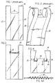
- Figures 1 and 2 show a typical prior art handle bag, generally designated at 10, both in a lay flat and partly open position.
- these bags include inwardly folded side edge gussets 12. After the bag is formed from a continuously running gusseted tube, seals are made to form the bag bottom and upper edge portion 14. After forming the sealed tube, a U-shaped cut out portion is cut away from the bag tube thereby forming an open mouth having handles 11 adjacent opposite edges of the mouth. In the area 13, located at the base of the opposite handles and inside the bag edge, severe stresses are encountered during bag loading operations when the bag is positioned as shown in Figure 5.
- pleats 15 may be positioned in spaced apart locations which generally correspond to areas 13.
- the individual bags vary in the configuration of the mouth cut out portion. It will be noted, for example, that the bag of Figure 4 is provided with tab 16 which may be fused to tags on similar bags in a stack so as to suspend the stack from a suitable support.
- Pleats 15 may be formed utilizing a convenient method such as for example impressing a flattened bag between matched metal rollers or plates during the bag forming operation.
- the rollers or plates are provided with peaks, e.g., truncated pyramids, together with mating recesses in an opposing plate or roller.
- An enlarged cross-section of one form of pleat configuration is shown in Figure 4A.
- an individual pleat length (the linear extent of the pleat from the bag mouth edge to its termination in the wall of the bag mouth) of about 20 to 25 mm. was effective.
- Figure 6 represents a graphic illustration of the improved tear resistance of the bag structure of the invention.
- the bags were fabricated from high density polyethylene having a thickness of about 25 microns. These bags were structurally similar to the bags shown in Figure 2, but no pleats were formed in the bags.
- a 3 mm. notch was cut in the machine direction in the cutout regions of each bag, 3 mm. from the gusset fold, as indicated by the arrows in Figure 4.
- the bag was opened and the opposite handle loops 11 were spread apart and draped over a pair of bag retaining fixtures which were positioned on the jaws of an Instron tensile tester ("Instron" is a trade mark).
- Instron is a trade mark
- Figure 6 plots the extension or the amount of jaw separation of the Instron tensile tester against the stress to bag failure.
- Figure 6 shows that the bags without the pleat structure exhibit failure at a stress value of less than 26,48 N. Conversely, when the pleated bag structure are tested, failure does not occur until the applied stress is almost 53,94 N.
- the pleats may be impressed by any suitable means, for example, by suitably shaped pressing dies or by toothed rolls.
- a preferred method employs toothed roll which engage the bag in the appropriate areas, to draw the plastic material and impress the pleats in it.
- the teeth in the rolls may be continuous or interrupted: in the former case the rolls will be oscillated so as to form a nip which engages the bags at the appropriate moment so that only the desired portion of the bag is impressed with the pleats; the rolls are then withdrawn from close engagement so that the pleated bag may be withdrawn and the next bag fed into the gap between the rolls before they move together again to form a nip for impressing the pleats.
- the bags can be fed continuously to the roll nip so that they are impressed as the toothed portions of the rolls come together. In both cases, of course, suitable feed mechanisms are necessary to ensure that the bags are fed to the rolls at the correct time so that the proper part of the bag is impressed with the pleats.
- the bags can be made by forming a pleated tube and cutting off and sealing the ends of individual bag lengths from the tube.
- the cutting and sealing may be done simultaneously on a twin-pleated tube by means of a suitable heated cutting and sealing device, e.g., a hot wire cutter/sealer.
- the mouth portion of the bag may then be cut out to form a structure similar to that shown in Figure 1.
- the mouth is cut so that the inner portions of the pleats are removed, forming the handle openings.
- the pleats may then be formed in the manner described above, using either a pressing die or indented rolls, preferably the latter.
- the bags can then be stacked on top of one another and, if the bag is of the configuration shown in Figure 4, the tabs between the handles can be fused together to keep the bags in a stack. If this is to be done, the tabs may include a perforated tear line to permit easy removal of the bags from the fused tabs.
- This type of bag is particularly useful where many bags are to be rapidly dispensed because the fused tabs can be held in a holder and the bags then tom off when they are needed. The perforations in the tabs can be made when the mouth cutout is made.
- the pleats may have different configurations: all that is necessary is that they be capable of extending under applied stress so as to provide stress relief in the mouth area of the bag.
- the pleats may be sinusoidal, saw-toothed, square-toothed (rectangular) or of any other configuration which will perform the desired purpose.
- Two particularly preferred configurations are the saw-toothed (V-shaped) and truncated saw-toothed (approximately U-shaped) configurations.
- Pleats of these configurations may be conveniently made by means of impressing dies or rolls with grooves of the appropriate shape.
- the saw-toothed pleats are best made by means of rolls which have flat-topped teeth and V-bottomed grooves: the use of flat-topped teeth helps to prevent the plastic film being cut as it is drawn out by the teeth entering the V-bottomed grooves of the opposing, mating die or roll.
- Other pleat configurations can, of course, be made by the use of suitably contoured dies or rolls.
Landscapes
- Engineering & Computer Science (AREA)
- Mechanical Engineering (AREA)
- Bag Frames (AREA)
- Making Paper Articles (AREA)
Claims (1)
- Beutel aus hemoplastischem Material mit einer Vorder- und einer Rückwand, einer Offnung und zwei Handgriffen (11), die einstückig mit der Vorder- und der Rückwand ausgebildet und an einander gegenüberliegenden Enden der Öffnung angeordnet sind, dadurch gekennzeichnet, daß mehrere eingepresste Falten (15) entlang der Kante de Beutelöffnung und/oder im Bereich (13) der Beutelwände, der dem unteren Abschnitt der Handgriffe (11) benachbart ist, angeordnet sind.
Applications Claiming Priority (2)
| Application Number | Priority Date | Filing Date | Title |
|---|---|---|---|
| US2089979A | 1979-03-15 | 1979-03-15 | |
| US20899 | 1979-03-15 |
Publications (2)
| Publication Number | Publication Date |
|---|---|
| EP0016601A1 EP0016601A1 (de) | 1980-10-01 |
| EP0016601B1 true EP0016601B1 (de) | 1983-02-16 |
Family
ID=21801181
Family Applications (1)
| Application Number | Title | Priority Date | Filing Date |
|---|---|---|---|
| EP19800300740 Expired EP0016601B1 (de) | 1979-03-15 | 1980-03-11 | Beutel aus thermoplastischem Material |
Country Status (4)
| Country | Link |
|---|---|
| EP (1) | EP0016601B1 (de) |
| CA (1) | CA1142898A (de) |
| DE (1) | DE3061964D1 (de) |
| ES (1) | ES249356Y (de) |
Cited By (2)
| Publication number | Priority date | Publication date | Assignee | Title |
|---|---|---|---|---|
| US6059707A (en) | 1998-03-27 | 2000-05-09 | Tenneco Packaging Inc. | Easy to open handle bag and method of making the same |
| US6611996B2 (en) | 2001-07-02 | 2003-09-02 | Pactiv Corporation | Slider for reclosable fastener |
Families Citing this family (3)
| Publication number | Priority date | Publication date | Assignee | Title |
|---|---|---|---|---|
| US4613988A (en) * | 1984-02-29 | 1986-09-23 | Mobil Oil Corporation | Thermoplastic bag and method of forming the same |
| US6713152B2 (en) | 2001-09-07 | 2004-03-30 | Pactiv Corporation | Fins and profiles for plastic bags |
| FR2847157A1 (fr) * | 2002-11-14 | 2004-05-21 | Luc Raymond Marie Morin | Protection hygienique a usage unique pour appuie-pied gynecologique |
Family Cites Families (3)
| Publication number | Priority date | Publication date | Assignee | Title |
|---|---|---|---|---|
| US3180557A (en) * | 1962-07-10 | 1965-04-27 | Celloplast Ab | Bag with handle of weldable plastic material |
| DE1486724B1 (de) * | 1964-11-30 | 1971-04-29 | Windmoeller & Hoelscher | Vorratsblock aus kunststoff-warenbeuteln |
| US4085822A (en) * | 1975-12-04 | 1978-04-25 | Mobil Oil Corporation | Bag assembly and method and apparatus for loading individual bags |
-
1980
- 1980-03-10 CA CA000347368A patent/CA1142898A/en not_active Expired
- 1980-03-11 DE DE8080300740T patent/DE3061964D1/de not_active Expired
- 1980-03-11 EP EP19800300740 patent/EP0016601B1/de not_active Expired
- 1980-03-14 ES ES1980249356U patent/ES249356Y/es not_active Expired
Cited By (2)
| Publication number | Priority date | Publication date | Assignee | Title |
|---|---|---|---|---|
| US6059707A (en) | 1998-03-27 | 2000-05-09 | Tenneco Packaging Inc. | Easy to open handle bag and method of making the same |
| US6611996B2 (en) | 2001-07-02 | 2003-09-02 | Pactiv Corporation | Slider for reclosable fastener |
Also Published As
| Publication number | Publication date |
|---|---|
| EP0016601A1 (de) | 1980-10-01 |
| CA1142898A (en) | 1983-03-15 |
| ES249356Y (es) | 1981-02-16 |
| DE3061964D1 (en) | 1983-03-24 |
| ES249356U (es) | 1980-08-16 |
Similar Documents
| Publication | Publication Date | Title |
|---|---|---|
| US4401427A (en) | Thermoplastic bags and method of making | |
| US6350057B1 (en) | Reinforced reclosable package seals | |
| US5695064A (en) | Self-opening plastic bag pack system | |
| US4781474A (en) | Pouch with loop handle attached by oval seal | |
| EP0341739B1 (de) | Perforiertes Material | |
| CA1235674A (en) | Thermoplastic bag pack | |
| US4895611A (en) | Method and apparatus for making non-roping thermoplastic draw tape for thermplastic bags | |
| US4326664A (en) | Thermoplastic bags having stress relief feature at handle connection | |
| US4278198A (en) | Flexible collapsible container with a stiffening member | |
| EP0080707B1 (de) | Vorrichtung um einen Kunststoffilm zu halten | |
| US5865313A (en) | Plastic bag pack system with novel handle apertures | |
| EP0016601B1 (de) | Beutel aus thermoplastischem Material | |
| US6015373A (en) | Method for wicket-top converting of a cross-laminated synthetic resin fiber mesh bag | |
| US4744200A (en) | Thermoplastic bag pack with single tab suspension | |
| US3533331A (en) | Method of forming continuous strip of bags | |
| JPH11236060A (ja) | 包装袋 | |
| US6080093A (en) | Apparatus for wicket-top converting of a cross-laminated synthetic resin fiber mesh bag | |
| US20040001652A1 (en) | Packaging bag, and method of and apparatus for manufacturing the same | |
| US4822437A (en) | Method and apparatus for making non-roping thermoplastic draw tape for thermoplastic bags | |
| US3153481A (en) | Plastic articles | |
| WO1996015039A1 (en) | A roll-pack of plastic bags designed to allow the extemporaneous removal of separate, individual bags | |
| GB2264690A (en) | Gusseted carrier bags | |
| JPH10147322A (ja) | ヘッダ付き袋の製袋方法 | |
| EP1375366A1 (de) | Verpackungsbeutel sowie Verfahren und Vorrichtung zu dessen Herstellung | |
| CA1284969C (en) | Thermoplastic bag, bag pack and method of making the same |
Legal Events
| Date | Code | Title | Description |
|---|---|---|---|
| PUAI | Public reference made under article 153(3) epc to a published international application that has entered the european phase |
Free format text: ORIGINAL CODE: 0009012 |
|
| AK | Designated contracting states |
Designated state(s): BE DE FR GB IT NL |
|
| 17P | Request for examination filed |
Effective date: 19801017 |
|
| ITF | It: translation for a ep patent filed | ||
| GRAA | (expected) grant |
Free format text: ORIGINAL CODE: 0009210 |
|
| AK | Designated contracting states |
Designated state(s): BE DE FR GB IT NL |
|
| REF | Corresponds to: |
Ref document number: 3061964 Country of ref document: DE Date of ref document: 19830324 |
|
| ET | Fr: translation filed | ||
| PGFP | Annual fee paid to national office [announced via postgrant information from national office to epo] |
Ref country code: DE Payment date: 19881220 Year of fee payment: 10 |
|
| PGFP | Annual fee paid to national office [announced via postgrant information from national office to epo] |
Ref country code: GB Payment date: 19890311 Year of fee payment: 10 |
|
| PGFP | Annual fee paid to national office [announced via postgrant information from national office to epo] |
Ref country code: BE Payment date: 19890313 Year of fee payment: 10 |
|
| ITTA | It: last paid annual fee | ||
| PGFP | Annual fee paid to national office [announced via postgrant information from national office to epo] |
Ref country code: FR Payment date: 19890331 Year of fee payment: 10 Ref country code: NL Payment date: 19890331 Year of fee payment: 10 |
|
| PG25 | Lapsed in a contracting state [announced via postgrant information from national office to epo] |
Ref country code: GB Effective date: 19900311 |
|
| PG25 | Lapsed in a contracting state [announced via postgrant information from national office to epo] |
Ref country code: BE Effective date: 19900331 |
|
| BERE | Be: lapsed |
Owner name: MOBIL OIL CORP. Effective date: 19900331 |
|
| PG25 | Lapsed in a contracting state [announced via postgrant information from national office to epo] |
Ref country code: NL Effective date: 19901001 |
|
| GBPC | Gb: european patent ceased through non-payment of renewal fee | ||
| NLV4 | Nl: lapsed or anulled due to non-payment of the annual fee | ||
| PG25 | Lapsed in a contracting state [announced via postgrant information from national office to epo] |
Ref country code: FR Effective date: 19901130 |
|
| PG25 | Lapsed in a contracting state [announced via postgrant information from national office to epo] |
Ref country code: DE Effective date: 19901201 |
|
| REG | Reference to a national code |
Ref country code: FR Ref legal event code: ST |
|
| PLBE | No opposition filed within time limit |
Free format text: ORIGINAL CODE: 0009261 |
|
| STAA | Information on the status of an ep patent application or granted ep patent |
Free format text: STATUS: NO OPPOSITION FILED WITHIN TIME LIMIT |