EP0016489B1 - Homokinetic coupling - Google Patents
Homokinetic coupling Download PDFInfo
- Publication number
- EP0016489B1 EP0016489B1 EP80200189A EP80200189A EP0016489B1 EP 0016489 B1 EP0016489 B1 EP 0016489B1 EP 80200189 A EP80200189 A EP 80200189A EP 80200189 A EP80200189 A EP 80200189A EP 0016489 B1 EP0016489 B1 EP 0016489B1
- Authority
- EP
- European Patent Office
- Prior art keywords
- ring
- inner ring
- ball
- coupling according
- socket
- Prior art date
- Legal status (The legal status is an assumption and is not a legal conclusion. Google has not performed a legal analysis and makes no representation as to the accuracy of the status listed.)
- Expired
Links
- 230000008878 coupling Effects 0.000 title claims description 42
- 238000010168 coupling process Methods 0.000 title claims description 42
- 238000005859 coupling reaction Methods 0.000 title claims description 42
- 238000007789 sealing Methods 0.000 claims description 7
- 230000033001 locomotion Effects 0.000 claims description 2
- 238000006073 displacement reaction Methods 0.000 claims 1
- 238000010276 construction Methods 0.000 description 2
- 239000002184 metal Substances 0.000 description 2
- 238000004519 manufacturing process Methods 0.000 description 1
- 230000035939 shock Effects 0.000 description 1
Images

Classifications
-
- F—MECHANICAL ENGINEERING; LIGHTING; HEATING; WEAPONS; BLASTING
- F16—ENGINEERING ELEMENTS AND UNITS; GENERAL MEASURES FOR PRODUCING AND MAINTAINING EFFECTIVE FUNCTIONING OF MACHINES OR INSTALLATIONS; THERMAL INSULATION IN GENERAL
- F16D—COUPLINGS FOR TRANSMITTING ROTATION; CLUTCHES; BRAKES
- F16D3/00—Yielding couplings, i.e. with means permitting movement between the connected parts during the drive
- F16D3/16—Universal joints in which flexibility is produced by means of pivots or sliding or rolling connecting parts
- F16D3/20—Universal joints in which flexibility is produced by means of pivots or sliding or rolling connecting parts one coupling part entering a sleeve of the other coupling part and connected thereto by sliding or rolling members
- F16D3/22—Universal joints in which flexibility is produced by means of pivots or sliding or rolling connecting parts one coupling part entering a sleeve of the other coupling part and connected thereto by sliding or rolling members the rolling members being balls, rollers, or the like, guided in grooves or sockets in both coupling parts
- F16D3/223—Universal joints in which flexibility is produced by means of pivots or sliding or rolling connecting parts one coupling part entering a sleeve of the other coupling part and connected thereto by sliding or rolling members the rolling members being balls, rollers, or the like, guided in grooves or sockets in both coupling parts the rolling members being guided in grooves in both coupling parts
- F16D3/224—Universal joints in which flexibility is produced by means of pivots or sliding or rolling connecting parts one coupling part entering a sleeve of the other coupling part and connected thereto by sliding or rolling members the rolling members being balls, rollers, or the like, guided in grooves or sockets in both coupling parts the rolling members being guided in grooves in both coupling parts the groove centre-lines in each coupling part lying on a sphere
-
- F—MECHANICAL ENGINEERING; LIGHTING; HEATING; WEAPONS; BLASTING
- F16—ENGINEERING ELEMENTS AND UNITS; GENERAL MEASURES FOR PRODUCING AND MAINTAINING EFFECTIVE FUNCTIONING OF MACHINES OR INSTALLATIONS; THERMAL INSULATION IN GENERAL
- F16D—COUPLINGS FOR TRANSMITTING ROTATION; CLUTCHES; BRAKES
- F16D3/00—Yielding couplings, i.e. with means permitting movement between the connected parts during the drive
- F16D3/16—Universal joints in which flexibility is produced by means of pivots or sliding or rolling connecting parts
- F16D3/20—Universal joints in which flexibility is produced by means of pivots or sliding or rolling connecting parts one coupling part entering a sleeve of the other coupling part and connected thereto by sliding or rolling members
- F16D3/22—Universal joints in which flexibility is produced by means of pivots or sliding or rolling connecting parts one coupling part entering a sleeve of the other coupling part and connected thereto by sliding or rolling members the rolling members being balls, rollers, or the like, guided in grooves or sockets in both coupling parts
- F16D3/223—Universal joints in which flexibility is produced by means of pivots or sliding or rolling connecting parts one coupling part entering a sleeve of the other coupling part and connected thereto by sliding or rolling members the rolling members being balls, rollers, or the like, guided in grooves or sockets in both coupling parts the rolling members being guided in grooves in both coupling parts
- F16D2003/22309—Details of grooves
-
- Y—GENERAL TAGGING OF NEW TECHNOLOGICAL DEVELOPMENTS; GENERAL TAGGING OF CROSS-SECTIONAL TECHNOLOGIES SPANNING OVER SEVERAL SECTIONS OF THE IPC; TECHNICAL SUBJECTS COVERED BY FORMER USPC CROSS-REFERENCE ART COLLECTIONS [XRACs] AND DIGESTS
- Y10—TECHNICAL SUBJECTS COVERED BY FORMER USPC
- Y10S—TECHNICAL SUBJECTS COVERED BY FORMER USPC CROSS-REFERENCE ART COLLECTIONS [XRACs] AND DIGESTS
- Y10S464/00—Rotary shafts, gudgeons, housings, and flexible couplings for rotary shafts
- Y10S464/904—Homokinetic coupling
- Y10S464/906—Torque transmitted via radially spaced balls
Definitions
- the invention relates to a homokinetic coupling provided with an outer ring having a socket, an inner ring accommodated in the socket, and a number of flatted balls accommodated in groove-like ball races formed in the surface of the socket and in the surface of the inner ring respectively, to transmit rotation from the one ring to the other ring.
- the object of the invention is to provide a homokinetic coupling of simplified construction which making and assembling indeed being improved.
- the homokinetic coupling according to the invention is characterized in that the balls with their flat surfaces support on the curved bottom of the groove-like ball race of the inner ring and can freely adjust themselves to power transmitting motions. Freely means that no specific element such as a ring or the like engages the balls with a coupling part.
- the coupling according to the invention can lack the cage for steering or aligning the balls, and it has been found that by the specific arrangement of the flat portion of the balls on the spherical races, a self-aligning situation between the balls and the races during rotation can be created which favourably affects the operation of the coupling. For example by virtually silent rotation under load and flexible compensation of load variations at various angles has been observed.
- Another advantage of the coupling according to the invention is that the curved bottoms which cooperate with the flat surfaces of the balls are circular in axial section. This feature enables simplified manufacturing of coupling parts since no longer specific bottom curve- shapes of typical spheres are required.
- the coupling according to the invention can be executed such that the axial outer face of the inner ring is provided with a locking ring comprising spring elements which project into the ball races of said inner ring.
- the coupling according to the invention can be executed such that on the outer end of the outer ring, over the opening of the socket in the outer ring, a yielding sealing ring is arranged extending towards the inner ring or the locking ring.
- the coupling according to the invention consists essentially of a schematically represented outer ring 1, an inner ring 2, and a set of flatted balls 3, usually six, to transmit the rotations from the one ring to the other ring.
- the cage usually found in such homokinetic couplings to line up the balls is absent in the coupling according to the invention.
- the outer ring 1 is substantially of conventional construction for homokinetic couplings having complete spherical balls and a cage.
- the axis of rotation of the outer ring is indicated by A-M in Figs. 1 and 2.
- the outer ring 1 has a socket 4 of spherical surface 5 with center at M; in this surface 5, evenly spaced around the axis of rotation A-M, as many groove-like ball races 6 are formed as there are balls 3.
- the ball races 6 are generally oriented along planes passing through the axis of rotation A-M. In Figs. 1 and 2, the bottoms of the grooves of ball races 6 are indicated by circular arcs 7, showing that the ball races 6 become deeper towards the opening 8 of socket 4 towards the outer end of the outer ring 1.
- the socket 4 of the outer ring 1 accommodates the inner ring 2, whose axis of rotation is indicated in Figs. 1 and 2 by B-M.
- the axes of rotation A-M and B-M of the outer ring 1 and inner ring 2 lie in each other's extension, and in Fig. 2 they are at their maximum angle of deflection, about 40°.
- the inner ring 2 has a spherical outer surface 9 with center M, which outer surface 9 rests directly on the spherical surface 5 of the socket 4 of the outer ring 1.
- the spherical outer surface 9 of the inner ring 2 evenly spaced around the axis of rotation B-M, there are as many groove-like ball races 10 as there are balls 3.
- the ball races 10 are generally oriented in planes passing through the axis of rotation B-M of the inner ring 2.
- the bottoms of the grooves of the ball races 10 are indicated by circular arcs 11, showing that the ball races 10 become deeper from the inner end 12 of the inner ring 2 outward.
- Each ball 3 is accommodated partly in a ball race 6 of the outer ring 1 and partly in a ball race 10 of the inner ring 2.
- the balls 3 used in the coupling according to the invention are of the flatted type pictured in Fig. 3, with a flat face 13.
- the flatting of the balls 3 is such that the altitude p of the spherical segment missing from the sphere 3 because of the flatting is at least 1/5 of the spherical diameter d of the ball 3 (see Fig. 3).
- the flat faces 13 of the balls 3 cooperate rotatably and/or displaceably with the bottoms 11 of the ball races 10 of the inner ring 2; as shown especially in Fig. 4, the bottoms 11 of the grooves are specially shaped for this purpose, being rectilinear in cross section in planes perpendicular to the axis of rotation B-M of the inner ring 1, so that line contact of the bottom 11 of the groove with the flat face 13 of the ball 3 is always obtained, along a line crossing the axis of rotation B-M of the inner ring 2 perpendicularly.
- the width of the bottom 11 of the groove is equal to the diameter of the flat face 13 of the ball 3.
- the ball races 10 of the inner ring 2 are bound by opposed side walls 14, 15 pictured in particular in Fig. 4, showing that the said side walls 14, 15 are adapted in shape to the spherical portion of the balls 3 with which they come into contact, to lock the balls 3 between them in the circumferential direction of the inner ring 2.
- the erect walls 14, 15 lie symmetrically at equal distances from the central axial plane of a ball race 10, so that the line of contact of the flat face 13 of the ball 3 with the bottom 11 of the groove is perpendicular to the said central axial plane (the plane of the drawing in Fig. 5).
- the inner ring 2 has a flat outer face 16, pictured in Figs. 4 and 5, on which a lock ring 17 is mounted, shown loose in Figs. 6 and 7. This may be done for example by means of screws, not shown, inserted through holes 18 in the lock ring 17 and screwed into corresponding threaded holes 19 in the inner ring 2.
- the lock ring 17 closes off the right-hand ends of the ball races 10 of the inner ring to retain the balls 3.
- Figs. 1 and 2 the lock ring 17 closes off the right-hand ends of the ball races 10 of the inner ring to retain the balls 3.
- the lock ring 17 also bears spring members 20 projecting into the ball races 10 of the inner ring 2 and serving to absorb shocks from the balls 3.
- the spiral leaf springs shown, accommodated in recessed round seats 26 of lock ring 17, are found to suffice.
- a rubber sealing ring 21 is arranged, projecting towards the lock ring 17 or the inner ring 2.
- the sealing ring 21 is fixed against the outer end of the outer ring 1 by a metal ring 22; the rubber sealing ring 21 projects over the opening 8 beyond the metal ring 22, so that the rubber sealing ring 21 can give way when struck by a ball 3, as indicated in Fig. 2, at a large deflection of the axes A-M and B-M.
- the sealing ring 21 then keeps the balls free from dropping out of the coupling.
- Figs. 1 and 2 further schematically show the conventional drive shaft 23, passed through a bore 24 in the lock ring 17 and into a bore 25 of the inner ring 2, where it is secured against rotation by splines not shown.
- the assembly of the coupling according to the invention is simplified by the absence of a cage, and is carried out axially, the inner ring 2 being first placed in the socket 4 of the outer ring 1, after which the balls are arranged in the ball races 6, 10 and then the lock ring 17 is assembled with the inner ring 2.
- the characteristic result of the improvement is that the flat face of a ball is freely rotatable and/or displaceable over the curved surface of a race, i.e. the balls are not forced or steered by a cage, pin members or the like elements, but being able to be displaced mainly under influence of the rotational forces between the two homokinetic coupling rings.
Landscapes
- Engineering & Computer Science (AREA)
- General Engineering & Computer Science (AREA)
- Mechanical Engineering (AREA)
- Rolling Contact Bearings (AREA)
- Pivots And Pivotal Connections (AREA)
- Bearings For Parts Moving Linearly (AREA)
- Pens And Brushes (AREA)
- Orthopedics, Nursing, And Contraception (AREA)
- Mutual Connection Of Rods And Tubes (AREA)
- Joints With Pressure Members (AREA)
Description
- The invention relates to a homokinetic coupling provided with an outer ring having a socket, an inner ring accommodated in the socket, and a number of flatted balls accommodated in groove-like ball races formed in the surface of the socket and in the surface of the inner ring respectively, to transmit rotation from the one ring to the other ring.
- Such a homokinetic coupling is disclosed by British patent 1.500.768. This type of coupling is provided with a cage arranged between the outer ring and the inner ring and having apertures in which the balls are accommodated; this cage aligns or steers the balls in the bisecting plane. These balls with their flat surfaces are located against the sides of the cage-apertures and with their spherical portions positioned in straight ball races of both the outer ring and inner ring.
- The object of the invention is to provide a homokinetic coupling of simplified construction which making and assembling indeed being improved.
- For this purpose, the homokinetic coupling according to the invention is characterized in that the balls with their flat surfaces support on the curved bottom of the groove-like ball race of the inner ring and can freely adjust themselves to power transmitting motions. Freely means that no specific element such as a ring or the like engages the balls with a coupling part.
- As a result, the coupling according to the invention can lack the cage for steering or aligning the balls, and it has been found that by the specific arrangement of the flat portion of the balls on the spherical races, a self-aligning situation between the balls and the races during rotation can be created which favourably affects the operation of the coupling. For example by virtually silent rotation under load and flexible compensation of load variations at various angles has been observed.
- US patent 2.140.295 discloses a universal joint which lacks a separate steering cage. However the balls in this design are located in spaces formed by coupling parts for which they need to support against each other. It therefore can be stated that these coupling parts form a kind of cage by means of which the balls are locked up.
- Another advantage of the coupling according to the invention is that the curved bottoms which cooperate with the flat surfaces of the balls are circular in axial section. This feature enables simplified manufacturing of coupling parts since no longer specific bottom curve- shapes of typical spheres are required.
- Further, the coupling according to the invention can be executed such that the axial outer face of the inner ring is provided with a locking ring comprising spring elements which project into the ball races of said inner ring. By this measure in a simple way fall out of balls during rotation at maximum angled positions of the coupling parts is prevented. The coupling according to the invention has the additional advantage that assembly, owing to the absence of a cage for the ball, can now be carried out in a more convenient manner namely axially.
- Alternatively, the coupling according to the invention can be executed such that on the outer end of the outer ring, over the opening of the socket in the outer ring, a yielding sealing ring is arranged extending towards the inner ring or the locking ring.
- The invention will now be described with reference to the drawing, showing an embodiment of the homokinetic coupling of the invention by way of example.
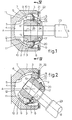
- Fig. 1 is an axial section of the homokinetic coupling according to the invention in the condition where the shafts to be coupled lie in line with each other.
- Fig. 2 is an axial section of the coupling of Fig. 1 with maximum deflection of the shafts.
- Fig. 3 is a view of the flatted type ball used in the coupling according to the invention.
- Fig. 4 is a front view of the detached inner ring of the coupling, seen in the direction of the arrows IV-IV in Fig. 1.
- Fig. 5 is an axial section of the inner ring, viewed along the arrows V-V in Fig. 4.
- Fig. 6 is a side view of a detached lock ring to be screwed onto the inner ring to lock in the balls.
- Fig. 7 is a back view of the lock ring, seen in the direction of the arrows VII-VII in Fig. 6.
- As is shown in Figs. 1 and 2, the coupling according to the invention consists essentially of a schematically represented
outer ring 1, aninner ring 2, and a set offlatted balls 3, usually six, to transmit the rotations from the one ring to the other ring. The cage usually found in such homokinetic couplings to line up the balls is absent in the coupling according to the invention. Theouter ring 1 is substantially of conventional construction for homokinetic couplings having complete spherical balls and a cage. The axis of rotation of the outer ring is indicated by A-M in Figs. 1 and 2. Theouter ring 1 has asocket 4 ofspherical surface 5 with center at M; in thissurface 5, evenly spaced around the axis of rotation A-M, as many groove-like ball races 6 are formed as there areballs 3. Theball races 6 are generally oriented along planes passing through the axis of rotation A-M. In Figs. 1 and 2, the bottoms of the grooves ofball races 6 are indicated bycircular arcs 7, showing that theball races 6 become deeper towards the opening 8 ofsocket 4 towards the outer end of theouter ring 1. - The
socket 4 of theouter ring 1 accommodates theinner ring 2, whose axis of rotation is indicated in Figs. 1 and 2 by B-M. In Fig. 1, the axes of rotation A-M and B-M of theouter ring 1 andinner ring 2 lie in each other's extension, and in Fig. 2 they are at their maximum angle of deflection, about 40°. Theinner ring 2 has a sphericalouter surface 9 with center M, whichouter surface 9 rests directly on thespherical surface 5 of thesocket 4 of theouter ring 1. In the sphericalouter surface 9 of theinner ring 2, evenly spaced around the axis of rotation B-M, there are as many groove-like ball races 10 as there areballs 3. Theball races 10 are generally oriented in planes passing through the axis of rotation B-M of theinner ring 2. In Figs. 1, 2 and 5, the bottoms of the grooves of theball races 10 are indicated bycircular arcs 11, showing that theball races 10 become deeper from theinner end 12 of theinner ring 2 outward. Eachball 3 is accommodated partly in aball race 6 of theouter ring 1 and partly in aball race 10 of theinner ring 2. Theballs 3 used in the coupling according to the invention are of the flatted type pictured in Fig. 3, with aflat face 13. According to the invention, the flatting of theballs 3 is such that the altitude p of the spherical segment missing from thesphere 3 because of the flatting is at least 1/5 of the spherical diameter d of the ball 3 (see Fig. 3). - According to the invention, the
flat faces 13 of theballs 3 cooperate rotatably and/or displaceably with thebottoms 11 of theball races 10 of theinner ring 2; as shown especially in Fig. 4, thebottoms 11 of the grooves are specially shaped for this purpose, being rectilinear in cross section in planes perpendicular to the axis of rotation B-M of theinner ring 1, so that line contact of thebottom 11 of the groove with theflat face 13 of theball 3 is always obtained, along a line crossing the axis of rotation B-M of theinner ring 2 perpendicularly. The width of thebottom 11 of the groove is equal to the diameter of theflat face 13 of theball 3. - In addition, the
ball races 10 of theinner ring 2 are bound byopposed side walls side walls balls 3 with which they come into contact, to lock theballs 3 between them in the circumferential direction of theinner ring 2. Thus theerect walls ball race 10, so that the line of contact of theflat face 13 of theball 3 with thebottom 11 of the groove is perpendicular to the said central axial plane (the plane of the drawing in Fig. 5). - Surprisingly, it has been found that in the coupling according to the invention, lacking a ball cage, the
balls 3 will align themselves. Theinner ring 2 has a flatouter face 16, pictured in Figs. 4 and 5, on which alock ring 17 is mounted, shown loose in Figs. 6 and 7. This may be done for example by means of screws, not shown, inserted throughholes 18 in thelock ring 17 and screwed into corresponding threadedholes 19 in theinner ring 2. In assembled condition, as shown in Figs. 1 and 2, thelock ring 17 closes off the right-hand ends of theball races 10 of the inner ring to retain theballs 3. As shown in particular in Figs. 1 and 2, thelock ring 17 also bearsspring members 20 projecting into theball races 10 of theinner ring 2 and serving to absorb shocks from theballs 3. For this purpose, the spiral leaf springs shown, accommodated in recessedround seats 26 oflock ring 17, are found to suffice. Besides, at the outer end of theouter ring 1, over themouth 8 of thesocket 4, arubber sealing ring 21 is arranged, projecting towards thelock ring 17 or theinner ring 2. Thesealing ring 21 is fixed against the outer end of theouter ring 1 by ametal ring 22; therubber sealing ring 21 projects over the opening 8 beyond themetal ring 22, so that therubber sealing ring 21 can give way when struck by aball 3, as indicated in Fig. 2, at a large deflection of the axes A-M and B-M. The sealingring 21 then keeps the balls free from dropping out of the coupling. - Figs. 1 and 2 further schematically show the
conventional drive shaft 23, passed through abore 24 in thelock ring 17 and into abore 25 of theinner ring 2, where it is secured against rotation by splines not shown. - The assembly of the coupling according to the invention is simplified by the absence of a cage, and is carried out axially, the
inner ring 2 being first placed in thesocket 4 of theouter ring 1, after which the balls are arranged in theball races lock ring 17 is assembled with theinner ring 2. - The characteristic result of the improvement is that the flat face of a ball is freely rotatable and/or displaceable over the curved surface of a race, i.e. the balls are not forced or steered by a cage, pin members or the like elements, but being able to be displaced mainly under influence of the rotational forces between the two homokinetic coupling rings.
Claims (10)
Applications Claiming Priority (2)
| Application Number | Priority Date | Filing Date | Title |
|---|---|---|---|
| NL7902092 | 1979-03-16 | ||
| NL7902092A NL7902092A (en) | 1979-03-16 | 1979-03-16 | HOMOKINETIC COUPLING. |
Publications (2)
| Publication Number | Publication Date |
|---|---|
| EP0016489A1 EP0016489A1 (en) | 1980-10-01 |
| EP0016489B1 true EP0016489B1 (en) | 1984-06-27 |
Family
ID=19832818
Family Applications (1)
| Application Number | Title | Priority Date | Filing Date |
|---|---|---|---|
| EP80200189A Expired EP0016489B1 (en) | 1979-03-16 | 1980-03-03 | Homokinetic coupling |
Country Status (8)
| Country | Link |
|---|---|
| US (1) | US4358283A (en) |
| EP (1) | EP0016489B1 (en) |
| JP (2) | JPS55126125A (en) |
| BR (1) | BR8001470A (en) |
| DE (1) | DE3068337D1 (en) |
| ES (1) | ES489588A1 (en) |
| MX (1) | MX149144A (en) |
| NL (1) | NL7902092A (en) |
Families Citing this family (16)
| Publication number | Priority date | Publication date | Assignee | Title |
|---|---|---|---|---|
| NL7909198A (en) * | 1979-12-20 | 1981-07-16 | Skf Ind Trading & Dev | HOMOKINETIC COUPLING. |
| NL8102379A (en) * | 1981-05-14 | 1982-12-01 | Skf Ind Trading & Dev | HOMOKINETIC COUPLING. |
| DE3209596C2 (en) * | 1982-03-17 | 1985-10-03 | Uni-Cardan Ag, 5200 Siegburg | Constant velocity swivel |
| US4685897A (en) * | 1985-02-22 | 1987-08-11 | Gkn Automotive Components Inc. | Universal joint for tilt steering wheel |
| US5230659A (en) * | 1987-08-20 | 1993-07-27 | Hardy Spicer Limited | Constant velocity ratio universal joint having improved centering of inner and outer joint members |
| GB8719657D0 (en) * | 1987-08-20 | 1987-09-30 | Spicer Hardy Ltd | Constant velocity ratio universal joint |
| US5201107A (en) * | 1990-08-29 | 1993-04-13 | Pmx Inc. | Method of assembling a constant velocity universal joint |
| JP3505020B2 (en) * | 1995-12-26 | 2004-03-08 | Ntn株式会社 | Fixed type constant velocity universal joint |
| US20020176905A1 (en) * | 2001-03-22 | 2002-11-28 | Fridley Michael A. | Self-aligning cutter hub assembly |
| US6536736B2 (en) * | 2001-07-16 | 2003-03-25 | Agilent Technologies, Inc. | Optomechanical mount for precisely steering/positioning a light beam |
| US6616537B2 (en) * | 2001-09-20 | 2003-09-09 | Delphi Technologies, Inc. | Constant velocity joint |
| US6808456B2 (en) * | 2002-12-03 | 2004-10-26 | Delphi Technologies, Inc. | Constant velocity joint |
| US7037072B2 (en) * | 2004-03-03 | 2006-05-02 | Carson Franklin D | Rotor head for a rotary-wing aircraft |
| US7365925B2 (en) * | 2006-03-30 | 2008-04-29 | Agilent Technologies, Inc. | Method of aligning optical elements |
| CN110319114B (en) * | 2018-03-30 | 2021-01-01 | 比亚迪股份有限公司 | Swing bearing and wearable device |
| CN113690701B (en) * | 2021-07-21 | 2024-05-31 | 长城信息股份有限公司 | Rotary limiting and concealed wiring type universal joint connector |
Family Cites Families (13)
| Publication number | Priority date | Publication date | Assignee | Title |
|---|---|---|---|---|
| US1500768A (en) * | 1922-06-10 | 1924-07-08 | Globe Wernicke Co | Ledger for machine posting |
| US1781450A (en) * | 1928-03-21 | 1930-11-11 | Charles M Eberling | Roller bearing |
| US2140295A (en) * | 1937-01-18 | 1938-12-13 | Logan L Mallard | Universal joint |
| GB637718A (en) * | 1946-05-16 | 1950-05-24 | William Cull | Improvements in and relating to torque transmitting universal joints |
| US2902844A (en) * | 1957-06-24 | 1959-09-08 | Alfred H Rzeppa | Universal joint |
| US3133432A (en) * | 1962-05-07 | 1964-05-19 | Dana Corp | Telescoping universal joint |
| GB1088615A (en) * | 1965-04-06 | 1967-10-25 | North Carolina Nat Bank | Constant velocity universal joint |
| FR1444895A (en) * | 1965-05-26 | 1966-07-08 | Glaenzer Spicer Sa | Constant velocity universal joint for transmission |
| US3381497A (en) * | 1966-10-10 | 1968-05-07 | Borg Warner | Universal joint |
| US3540235A (en) * | 1969-01-28 | 1970-11-17 | Houdaille Industries Inc | Wide angle constant velocity universal joint |
| JPS4841172B1 (en) * | 1970-01-21 | 1973-12-05 | ||
| JPS495128A (en) * | 1972-05-04 | 1974-01-17 | ||
| US4114404A (en) * | 1977-05-02 | 1978-09-19 | Dana Corporation | Universal joint |
-
1979
- 1979-03-16 NL NL7902092A patent/NL7902092A/en not_active Application Discontinuation
-
1980
- 1980-03-03 DE DE8080200189T patent/DE3068337D1/en not_active Expired
- 1980-03-03 EP EP80200189A patent/EP0016489B1/en not_active Expired
- 1980-03-06 US US06/127,809 patent/US4358283A/en not_active Expired - Lifetime
- 1980-03-10 JP JP2928980A patent/JPS55126125A/en active Pending
- 1980-03-12 BR BR8001470A patent/BR8001470A/en unknown
- 1980-03-14 ES ES489588A patent/ES489588A1/en not_active Expired
- 1980-03-14 MX MX181578A patent/MX149144A/en unknown
-
1984
- 1984-07-30 JP JP1984115101U patent/JPS6049333U/en active Pending
Also Published As
| Publication number | Publication date |
|---|---|
| MX149144A (en) | 1983-09-06 |
| JPS6049333U (en) | 1985-04-06 |
| ES489588A1 (en) | 1980-09-16 |
| US4358283A (en) | 1982-11-09 |
| DE3068337D1 (en) | 1984-08-02 |
| NL7902092A (en) | 1980-09-18 |
| JPS55126125A (en) | 1980-09-29 |
| BR8001470A (en) | 1980-11-11 |
| EP0016489A1 (en) | 1980-10-01 |
Similar Documents
| Publication | Publication Date | Title |
|---|---|---|
| US3306077A (en) | Universal joints | |
| US4358283A (en) | Universal joint | |
| US6869366B2 (en) | Universal joint | |
| KR100977450B1 (en) | Tripford type constant velocity joint | |
| US5026325A (en) | Constant velocity ratio plunging universal joint | |
| EP0050421B1 (en) | Constant velocity ratio universal joint | |
| EP0155467B1 (en) | Centering device for a constant velocity joint | |
| CS210671B2 (en) | Homokinetic transmission joint | |
| US3488979A (en) | Universal joints | |
| US4229952A (en) | Homokinetic universal joint | |
| US4685897A (en) | Universal joint for tilt steering wheel | |
| EP0065331B1 (en) | Homokinetic coupling | |
| US4000629A (en) | Homokinetic joint | |
| US6062982A (en) | Force transmitting apparatus | |
| US3357210A (en) | Constant velocity universal joint | |
| US4036032A (en) | Universal joint | |
| US3067595A (en) | Homokinetic universal joint | |
| US4279131A (en) | Constant velocity joint | |
| CA1230490A (en) | Shaft coupling for accommodating radial misalignment | |
| EP1671043B1 (en) | A transmission joint, in particular for transmitting drive between non-aligned shafts | |
| CA1274098A (en) | Universal joint | |
| US4070872A (en) | Universal joint | |
| KR20060047416A (en) | High Speed High Refractive Universal Joint | |
| US608625A (en) | Universal joint | |
| JPS59131032A (en) | Universal joint |
Legal Events
| Date | Code | Title | Description |
|---|---|---|---|
| PUAI | Public reference made under article 153(3) epc to a published international application that has entered the european phase |
Free format text: ORIGINAL CODE: 0009012 |
|
| AK | Designated contracting states |
Designated state(s): DE FR GB IT NL SE |
|
| 17P | Request for examination filed |
Effective date: 19810323 |
|
| ITF | It: translation for a ep patent filed | ||
| GRAA | (expected) grant |
Free format text: ORIGINAL CODE: 0009210 |
|
| AK | Designated contracting states |
Designated state(s): DE FR GB IT NL SE |
|
| REF | Corresponds to: |
Ref document number: 3068337 Country of ref document: DE Date of ref document: 19840802 |
|
| ET | Fr: translation filed | ||
| PLBE | No opposition filed within time limit |
Free format text: ORIGINAL CODE: 0009261 |
|
| STAA | Information on the status of an ep patent application or granted ep patent |
Free format text: STATUS: NO OPPOSITION FILED WITHIN TIME LIMIT |
|
| 26N | No opposition filed | ||
| PGFP | Annual fee paid to national office [announced via postgrant information from national office to epo] |
Ref country code: SE Payment date: 19910213 Year of fee payment: 12 |
|
| PGFP | Annual fee paid to national office [announced via postgrant information from national office to epo] |
Ref country code: DE Payment date: 19910220 Year of fee payment: 12 |
|
| PGFP | Annual fee paid to national office [announced via postgrant information from national office to epo] |
Ref country code: GB Payment date: 19910221 Year of fee payment: 12 Ref country code: FR Payment date: 19910221 Year of fee payment: 12 |
|
| ITTA | It: last paid annual fee | ||
| PGFP | Annual fee paid to national office [announced via postgrant information from national office to epo] |
Ref country code: NL Payment date: 19910331 Year of fee payment: 12 |
|
| PG25 | Lapsed in a contracting state [announced via postgrant information from national office to epo] |
Ref country code: GB Effective date: 19920303 |
|
| PG25 | Lapsed in a contracting state [announced via postgrant information from national office to epo] |
Ref country code: SE Effective date: 19920304 |
|
| PG25 | Lapsed in a contracting state [announced via postgrant information from national office to epo] |
Ref country code: NL Effective date: 19921001 |
|
| GBPC | Gb: european patent ceased through non-payment of renewal fee | ||
| NLV4 | Nl: lapsed or anulled due to non-payment of the annual fee | ||
| PG25 | Lapsed in a contracting state [announced via postgrant information from national office to epo] |
Ref country code: FR Effective date: 19921130 |
|
| PG25 | Lapsed in a contracting state [announced via postgrant information from national office to epo] |
Ref country code: DE Effective date: 19921201 |
|
| REG | Reference to a national code |
Ref country code: FR Ref legal event code: ST |
|
| EUG | Se: european patent has lapsed |
Ref document number: 80200189.1 Effective date: 19921005 |