EP0014940B1 - Component inserting apparatus - Google Patents
Component inserting apparatus Download PDFInfo
- Publication number
- EP0014940B1 EP0014940B1 EP80100698A EP80100698A EP0014940B1 EP 0014940 B1 EP0014940 B1 EP 0014940B1 EP 80100698 A EP80100698 A EP 80100698A EP 80100698 A EP80100698 A EP 80100698A EP 0014940 B1 EP0014940 B1 EP 0014940B1
- Authority
- EP
- European Patent Office
- Prior art keywords
- lead wires
- guide
- shaft member
- component
- circuit board
- Prior art date
- Legal status (The legal status is an assumption and is not a legal conclusion. Google has not performed a legal analysis and makes no representation as to the accuracy of the status listed.)
- Expired
Links
Images


Classifications
-
- H—ELECTRICITY
- H05—ELECTRIC TECHNIQUES NOT OTHERWISE PROVIDED FOR
- H05K—PRINTED CIRCUITS; CASINGS OR CONSTRUCTIONAL DETAILS OF ELECTRIC APPARATUS; MANUFACTURE OF ASSEMBLAGES OF ELECTRICAL COMPONENTS
- H05K13/00—Apparatus or processes specially adapted for manufacturing or adjusting assemblages of electric components
- H05K13/04—Mounting of components, e.g. of leadless components
- H05K13/0417—Feeding with belts or tapes
-
- H—ELECTRICITY
- H05—ELECTRIC TECHNIQUES NOT OTHERWISE PROVIDED FOR
- H05K—PRINTED CIRCUITS; CASINGS OR CONSTRUCTIONAL DETAILS OF ELECTRIC APPARATUS; MANUFACTURE OF ASSEMBLAGES OF ELECTRICAL COMPONENTS
- H05K13/00—Apparatus or processes specially adapted for manufacturing or adjusting assemblages of electric components
- H05K13/04—Mounting of components, e.g. of leadless components
- H05K13/0404—Pick-and-place heads or apparatus, e.g. with jaws
- H05K13/0408—Incorporating a pick-up tool
-
- Y—GENERAL TAGGING OF NEW TECHNOLOGICAL DEVELOPMENTS; GENERAL TAGGING OF CROSS-SECTIONAL TECHNOLOGIES SPANNING OVER SEVERAL SECTIONS OF THE IPC; TECHNICAL SUBJECTS COVERED BY FORMER USPC CROSS-REFERENCE ART COLLECTIONS [XRACs] AND DIGESTS
- Y10—TECHNICAL SUBJECTS COVERED BY FORMER USPC
- Y10T—TECHNICAL SUBJECTS COVERED BY FORMER US CLASSIFICATION
- Y10T29/00—Metal working
- Y10T29/49—Method of mechanical manufacture
- Y10T29/49002—Electrical device making
- Y10T29/49117—Conductor or circuit manufacturing
- Y10T29/49124—On flat or curved insulated base, e.g., printed circuit, etc.
- Y10T29/4913—Assembling to base an electrical component, e.g., capacitor, etc.
- Y10T29/49133—Assembling to base an electrical component, e.g., capacitor, etc. with component orienting
-
- Y—GENERAL TAGGING OF NEW TECHNOLOGICAL DEVELOPMENTS; GENERAL TAGGING OF CROSS-SECTIONAL TECHNOLOGIES SPANNING OVER SEVERAL SECTIONS OF THE IPC; TECHNICAL SUBJECTS COVERED BY FORMER USPC CROSS-REFERENCE ART COLLECTIONS [XRACs] AND DIGESTS
- Y10—TECHNICAL SUBJECTS COVERED BY FORMER USPC
- Y10T—TECHNICAL SUBJECTS COVERED BY FORMER US CLASSIFICATION
- Y10T29/00—Metal working
- Y10T29/53—Means to assemble or disassemble
- Y10T29/5313—Means to assemble electrical device
- Y10T29/53174—Means to fasten electrical component to wiring board, base, or substrate
- Y10T29/53183—Multilead component
Definitions
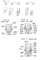
- the present invention generally relates to an assembling apparatus for electrical and electronic components or parts, and more particularly to a component inserting apparatus which is arranged to insert electric components or parts each having its lead wires extending in the same directions, for example, various electric components having different shapes such as ceramic capacitors (i.g. those shown in Figs. 1 (A) and 1 (B)), electrolytic capacitors (i.g. one shown in Fig. 1 (C)), vertical resistors (i.g. one shown in Fig. 1 (D)), transistors (i.g. one shown in Fig. 1 (E)) or the like into predetermined openings formed in a printed circuit board up to the root portions of the lead wires.
- ceramic capacitors i.g. those shown in Figs. 1 (A) and 1 (B)
- electrolytic capacitors i.g. one shown in Fig. 1 (C)
- vertical resistors i.g. one shown in Fig. 1 (D)
- transistors i.g. one shown in Fig
- one conventional apparatus of the above described type disclosed in US-A-3 777 350 (Fig. 26) comprises a gripping means 202 for gripping the body of an electric component 201, a vertically movable main shaft 203 having the gripping means mounted thereon, a pair of positioning cams 207 rotatably disposed around a horizontal shaft 204 under the gripping means 202 and having an insertion guide 206 with a guide groove 205 formed therein, a spring 208 for urging the insertion guide 206 in a direction along which the lower end of the insertion guide 206 is mutually narrowed, and an adjusting device 210 adapted to regulate the pivotal range of the insertion guide 206 by the spring 208 and mounted on a bearing 209.
- the motion of the insertion guide 206 in a direction along which the distance between the lower ends of the insertion guides 206 and 206 is spread is regulated.
- the lead wires of an electric component 201 gripped by the gripping means 202 descending together with the main shaft 203 are adapted to be guided to the given positions of the printed circuit board 211 by the insertion guide 206. Therefore, upon descending of the bearing 209, the insertion guide 206 contacts a given position of the printed circuit board 211. Then, the main shaft 203 descends to allow one portion of the main shaft 203 to come into contact against the positioning cam 207 thereby securing the insertion guide 206 (Fig.
- the lead wires of the electric component 201 are inserted into the given holes by the guide groove 205.
- the inserting operation is completed.
- One portion of the main shaft 203 and the positioning cam do not contact against each other, with the result that the insertion guide becomes rotatable (Fig. 3) around the horizontal shaft 204.
- the insertion guide 206 comes into contact against the body of the electric component 201 and is rotatable around the shaft 204, with the result that the insertion guide rises rotating in the direction of an arrow A (Fig. 4).
- the body of the electric component 201 comes into contact against the insertion guide 206.
- the insertion guide 206 is urged to rotate about the shaft 204, its rotation is blocked due to its contact with the printed circuit board and thus, the electric component 201 is prevented from being further inserted into the openings of the printed circuit board.
- an essential object of the present invention is to provide an apparatus for inserting lead wires of electric components or parts into predetermined openings of printed circuit boards up to roots of the lead wires regardless of sizes of the electric component bodies.
- a further object of the present invention is to provide a component inserting apparatus of the above described type which is simple in construction and accurate in functioning, and readily introduced into manufacturing processes of electrical and electronic equipment at low cost.
- the invention proceeds from the component mounting apparatus of the kind here concerned as disclosed in US-A-4 051 593 comprising a chuck means for gripping a body portion of a component to be inserted;
- insertion guide means for contacting at least one of the outer sides of each of the lead wires, in order to guide said wires into corresponding openings formed in said circuit board;
- said known apparatus is characterized in that
- a preferred embodiment of this component inserting apparatus in which the insertion guide means is rotated about a shaft disposed normal to the direction of the lead wires, comprises a further modification of said insertion guide means including a surface which is disposed only at one side of a plane containing a plurality of the lead wires so as to be approximately parallel with said plane so that said surface may confront the lead wires; and
- Fig. 5 a component inserting apparatus K according to one preferred embodiment of the present invention.
- the apparatus K generally includes a chuck element for gripping a body portion of each of the components having a plurality of lead wires extending outwardly therefrom in the same direction, insertion guide means which contacts outer sides of each of the lead wires so as to regulate the lead wires to be positioned at predetermined positions thereby to guide the lead wires into corresponding openings formed in the circuit board, a vertically movable guide shaft member for rotatably supporting said insertion guide means, and an insertion shaft member coupled with said chuck element so as to be movable in the same direction as that of said guide shaft member and also relatively with respect to the guide shaft member, which are described in detail hereinbelow.
- the tape transport units 1 are detachably mounted on a unit moving table 7 together with component accommodating reel units 8 arranged in a plurality of rows, the component accommodating reel units being each disposed at the rear portion of the corresponding tape transport unit in a line.
- the unit moving table 7 moves from side to side to shift a desired tape transport unit 1 to a given component taking-out position of a component cutter and transfer unit 9 of the component inserting apparatus.
- the component cutter and transfer unit 9 cuts off the lead wires 2 of the components at the given component taking-out position to separate them from the tape 5, forms the lead wires to a given size and shape and grips the lead wires to carry them to an insertion head unit 10 of the component inserting apparatus.
- a substrate moving unit 11 of the component inserting apparatus retains a set printed circuit board 12 to move it longitudinally and laterally thereby to bring requisite portions of the circuit board 12 into line with the insertion head unit 10.
- a drive control unit 13 controls the inserting operations for the unit moving table 7, substrate moving unit 11 and insertion head unit 10 in accordance with a predetermined program.
- the components to be inserted are received one by one by a rotary cutter of the insertion head unit 10 from the taped state in the belt-like configuration to be inserted into predetermined positions in the substrate.
- the taped component which has been fed over the tape transport unit 1 by a cutter unit 47 of the insertion head unit 10 and, then, the cut-off component 3 is received and held by a chuck element 48 after the clockwise rotation through an angle a in a horizontal plane.
- an insertion chuck unit body 81 of the component inserting apparatus is lowered in the direction of the arrow F for insertion of the component into the predetermined position of the circuit board 12.
- a cutter shaft 51 of the component inserting apparatus is arranged to rotate the cutter unit 47, which is detachably mounted, by a bolt, on the cutter shaft 51, while insertion guides 52, 52' or 52" are provided on a guide shaft 53 which is slidably provided on the insertion head unit 10 as shown in Fig. 7.
- a drive arm 55 connects to an insertion shaft 54 which is provided with the chuck unit body 81 at its nose or distal end and is vertically moved through a cam roller 57 of the drive arm 55 by the rotation of a cam 56 provided on the component inserting apparatus, while a guide shaft 53 is also vertically moved through a cam roller 57' of the drive arm 55' by the rotation of a cam 56' effecting synchronous rotation with the cam 56, with tension springs 58 and 58' being provided to urge the cam rollers toward the cams, respectively.
- a slide rack 59 rotates the cutter shaft 51 through a cam roller 61 by the rotation of a cam 60 provided on the component inserting apparatus.
- Slide shafts 62 and 62' allow the slide rack 59 to slide thereon, and there are also provided return springs 63 and 63' to urge the slide rack 59 toward the cam 60.
- a gear 64 is provided at the central portion of the cutter shaft 51 to engage the slide rack 59.
- the chuck body 81 rotatably supported at the distal end of the insertion shaft 54, and guide unit 151 or 151' located at the end of the guide shaft 53 are detachably mounted by bolts and are replaceable, respectively, by a chuck unit body 81' of another type and a guide unit 151' to be applied to another type of components as shown in Fig. 8.
- a cylinder 65 is mounted on the insertion head body 67 so that a pusher 66 mounted at the nose or distal portion of the piston rod of the cylinder may push the lever 22 through the roller 23 of the tape transport unit 1 when the tape transport unit 1 is located at the cut-off position. Meanwhile, the insertion head body 67 is mounted on a base 150 on the apparatus frame.
- a guide shaft 53 forms an insertion head and is slidably pivotable for vertical motion on the insertion head body 67.
- An insertion shaft 54 is slidably pivotable for vertical motion, at its shaft, into the inner hole of the guide shaft 53.
- An adjusting unit 101 is mounted in the top end screw of the guide shaft 53 and is adapted to vertically move the guide shaft 53 by the motion of the cam 56' through a pin 103 secured to the drive arm 55' and a roller 104 pivotally mounted on the pin 103.
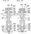
- the guide shaft 53 is provided, at its lower side end, with a guide unit 151 for supporting the chuck unit body 81 for electric component with two lead wires attached thereto.
- the guide unit 151 has a pair of insertion guides 52, 52' each mounted through a pin 153 thereon, the insertion guides 52, 52' being disposed in facing with each other at a given distance S (Fig. 10) corresponding to the conductor insertion pitch of the circuit printed board.
- a guide unit 151' is mounted to the lower front end of the guide shaft 53.
- An insertion guide 52" having grooves for guiding the three lead wires is rotatably mounted by a support point pin 153' on the guide unit 151'.
- an adjusting nut 102 is mounted on the top end screw of the insertion shaft 34 which is vertically moved by the motion of the cam 56 through a pin 103 secured to the drive arm 55 and a roller 104 rotatably mounted on the pin 103.
- the vertical oscillating motion imparted to the arms 55 and 55' by the cams 56 and 56' vertically slides the insertion shaft 54 and the guide shaft 53, respectively.
- the inserting shaft 54 and the guide shaft 53 starts to descend from the top dead center of the cam 56 and 56', respectively.
- the guide shaft 53 having the insertion guides 52, 52' or 52" is stopped just on the moment.
- the insertion shaft 54 further descends to insert the lead wires of the component into a given hole of the printed circuit board 12 and to attach the component body onto the board 12. After completing the insertion of the lead wires, the insertion shaft 54 and the guide shaft 53 rise up respectively by the cams 56 and 56'.
- the guide 52, 52 1 or 52" may be brought into the insertion hole without application of an external force upon the printed circuit board 12 to insert the lead wires of a component 3 thereinto.
- the insertion shaft 53 further descends to insert completely the lead wires of the component 3 into the printed circuit board up to the body bottom of the component 3 and then ascends.
- a crimped accessory of the lead wires can be inserted into a clearance provided between the printed circuit board top face and the component body.
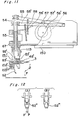
- a motor 115 is mounted on the base 150 on the apparatus frame 40.
- a clutch brake 116 is coupled to the motor 115.
- a drive shaft 117 is pivotally supported at its ends on the insertion head body 67.
- a pair of gears 118 and 119 engaged with each other are respectively mounted on the output shaft of the clutch brake 116 and on one end of the drive shaft 117.
- a timing pulley 120 is mounted on the drive shaft 117.
- a cam shaft 121 have two cams 56, 56' and 60 mounted thereon, the cams being adapted to rotate the cutter and oscillate the insertion head, respectively.
- a timing pulley 122 rotates the cam shaft 121 and a timing belt 123 connects the timing pulley 120 with the timing pulley 122.
- the cam shaft 121 is rotated to rotate the cutter unit 47 and to operate the chuck unit body 81 for inserting operation.
Description
- The present invention generally relates to an assembling apparatus for electrical and electronic components or parts, and more particularly to a component inserting apparatus which is arranged to insert electric components or parts each having its lead wires extending in the same directions, for example, various electric components having different shapes such as ceramic capacitors (i.g. those shown in Figs. 1 (A) and 1 (B)), electrolytic capacitors (i.g. one shown in Fig. 1 (C)), vertical resistors (i.g. one shown in Fig. 1 (D)), transistors (i.g. one shown in Fig. 1 (E)) or the like into predetermined openings formed in a printed circuit board up to the root portions of the lead wires.
- As shown in Fig. 2 to Fig. 4, one conventional apparatus of the above described type disclosed in US-A-3 777 350 (Fig. 26) comprises a
gripping means 202 for gripping the body of anelectric component 201, a vertically movablemain shaft 203 having the gripping means mounted thereon, a pair ofpositioning cams 207 rotatably disposed around ahorizontal shaft 204 under the gripping means 202 and having aninsertion guide 206 with aguide groove 205 formed therein, aspring 208 for urging theinsertion guide 206 in a direction along which the lower end of theinsertion guide 206 is mutually narrowed, and anadjusting device 210 adapted to regulate the pivotal range of theinsertion guide 206 by thespring 208 and mounted on abearing 209. When thepositioning cam 207 comes into contact against one portion of themain shaft 203 through the descent of themain shaft 203, the motion of theinsertion guide 206 in a direction along which the distance between the lower ends of theinsertion guides electric component 201 gripped by the gripping means 202 descending together with themain shaft 203 are adapted to be guided to the given positions of the printedcircuit board 211 by theinsertion guide 206. Therefore, upon descending of thebearing 209, theinsertion guide 206 contacts a given position of the printedcircuit board 211. Then, themain shaft 203 descends to allow one portion of themain shaft 203 to come into contact against thepositioning cam 207 thereby securing the insertion guide 206 (Fig. 2). Upon further descending of themain shaft 203, the lead wires of theelectric component 201 are inserted into the given holes by theguide groove 205. As some space is provided between the printedcircuit board 211 and the electric component body, the inserting operation is completed. One portion of themain shaft 203 and the positioning cam do not contact against each other, with the result that the insertion guide becomes rotatable (Fig. 3) around thehorizontal shaft 204. When themain shaft 203 and the bearing 209 rise, theinsertion guide 206 comes into contact against the body of theelectric component 201 and is rotatable around theshaft 204, with the result that the insertion guide rises rotating in the direction of an arrow A (Fig. 4). When the lead wires of theelectric component 201 are inserted up to the roots of the lead wires in this method, the body of theelectric component 201 comes into contact against theinsertion guide 206. Although theinsertion guide 206 is urged to rotate about theshaft 204, its rotation is blocked due to its contact with the printed circuit board and thus, theelectric component 201 is prevented from being further inserted into the openings of the printed circuit board. - Accordingly, an essential object of the present invention is to provide an apparatus for inserting lead wires of electric components or parts into predetermined openings of printed circuit boards up to roots of the lead wires regardless of sizes of the electric component bodies.
- A further object of the present invention is to provide a component inserting apparatus of the above described type which is simple in construction and accurate in functioning, and readily introduced into manufacturing processes of electrical and electronic equipment at low cost.
- The invention proceeds from the component mounting apparatus of the kind here concerned as disclosed in US-A-4 051 593 comprising a chuck means for gripping a body portion of a component to be inserted;
- insertion guide means for contacting at least one of the outer sides of each of the lead wires, in order to guide said wires into corresponding openings formed in said circuit board;
- said insertion guide means being attached to a vertically movable guide shaft member; and
- an insertion shaft member carrying said chuck means, being movable with respect to said guide shaft member.
- In accomplishing the above mentioned objects, said known apparatus is characterized in that
- (a) the insertion guide means are rotatably attached to the guide shaft member and are provided with a follower portion which contacts a cam recess formed in the insertion shaft member to rotate the insertion guide means in association with a relative movement of the insertion shaft member to the guide shaft member; and that
- (b) the guide shaft member and the insertion shaft member are provided with individual operating means to space during a later stage of the insertion of said component into said printed circuit board, the insertion guide means from said printed circuit board, thereby permitting said rotating movement of said insertion guide means, and the insertion of said lead wires up to their roots, into said printed circuit board.
- A preferred embodiment of this component inserting apparatus, in which the insertion guide means is rotated about a shaft disposed normal to the direction of the lead wires, comprises a further modification of said insertion guide means including a surface which is disposed only at one side of a plane containing a plurality of the lead wires so as to be approximately parallel with said plane so that said surface may confront the lead wires; and
- a guide groove for guiding the lead wires into the corresponding openings formed in the printed circuit board, which is formed on said surface.
- Further features, aspects and advantages of the present invention will become more apparent from the following detailed description of the preferred embodiment thereof taken in conjunction with the disclosure of US-A-4 051 593, and with reference to the accompanying drawings in which:
- Figs. 1 (A), 1 (B), 1 (C), 1 (D) and 1 (E) are perspective views each showing an example of an electric component to be dealt with by an inserting apparatus in accordance with the present invention (already referred to);
- Fig. 2 is a fragmentary sectional view showing a main portion of a conventional component inserting apparatus in a state immediately before the component is to be inserted into a printed circuit board (already referred to);
- Fig. 3 is a similar view to Fig. 2, but shows a state where the component has been inserted into the printed circuit board (already referred to);
- Fig. 4 is a similar view to Fig. 2, but shows a state where the component has been secured to the printed circuit board (already referred to);
- Fig. 5 is a perspective view of a component inserting apparatus according to one preferred embodiment of the present invention;
- Figs. 6(A) to 6(C) are fragmentary top plan views each showing an example of a belt-like component substrate;
- Fig. 7 is a perspective view showing essential portions of an insertion head unit for the electric component each having two lead wires;
- Fig. 8 is a fragmentary perspective view showing essential portions of the insertion head unit for electric components each having two or three lead wires;
- Fig. 9 is a front side sectional view of a head unit in a state where part of the lead wires have been inserted into the printed circuit board;
- Fig. 10 is a front side sectional view of the head unit at the bottom dead center;
- Fig. 11 is a side sectional view of the head unit, chuck element and guide unit during insertion of an electric component with three lead wires attached thereto;
- Fig. 12(A) is a fragmentary front side view of an insertion guide and a component during insertion of the electric component with three lead wires attached thereto;
- Fig. 12(B) is a fragmentary front side view of the insertion guide and component during insertion of the electric component with two lead wires attached thereto;
- Fig. 13 is a sectional view of the head unit in a state where the electronic component with three lead wires attached thereto has been partially inserted into the printed circuit board;
- Fig. 14 is a sectional view showing essential portions of the head unit at the bottom dead center;
- Fig. 15 is a cross-sectional view showing essential portions of the head unit at the top dead center; and
- Fig. 16 is a fragmentary diagram explanatory of driving of the insertion head unit.
- Before the description of the present invention proceeds, it is to be noted that like parts are designated by like reference numerals throughout several views of the accompanying drawings.
- Referring now to the drawings, there is shown in Fig. 5 a component inserting apparatus K according to one preferred embodiment of the present invention.
- The apparatus K generally includes a chuck element for gripping a body portion of each of the components having a plurality of lead wires extending outwardly therefrom in the same direction, insertion guide means which contacts outer sides of each of the lead wires so as to regulate the lead wires to be positioned at predetermined positions thereby to guide the lead wires into corresponding openings formed in the circuit board, a vertically movable guide shaft member for rotatably supporting said insertion guide means, and an insertion shaft member coupled with said chuck element so as to be movable in the same direction as that of said guide shaft member and also relatively with respect to the guide shaft member, which are described in detail hereinbelow.
- Referring particularly to Figs. 5 and 6, a belt-
like component substrate 6 in which a plurality ofelectric components 3 each havinglead wires adhesive tape 5 on aflexible tape 4, for example, of paper or the like, is engaged with a tape transport unit 1 of a component inserting apparatus. The tape transport units 1 are detachably mounted on a unit moving table 7 together with componentaccommodating reel units 8 arranged in a plurality of rows, the component accommodating reel units being each disposed at the rear portion of the corresponding tape transport unit in a line. The unit moving table 7 moves from side to side to shift a desired tape transport unit 1 to a given component taking-out position of a component cutter andtransfer unit 9 of the component inserting apparatus. The component cutter andtransfer unit 9 cuts off the lead wires 2 of the components at the given component taking-out position to separate them from thetape 5, forms the lead wires to a given size and shape and grips the lead wires to carry them to aninsertion head unit 10 of the component inserting apparatus. A substrate moving unit 11 of the component inserting apparatus retains a set printedcircuit board 12 to move it longitudinally and laterally thereby to bring requisite portions of thecircuit board 12 into line with theinsertion head unit 10. Adrive control unit 13 controls the inserting operations for the unit moving table 7, substrate moving unit 11 andinsertion head unit 10 in accordance with a predetermined program. - The components to be inserted are received one by one by a rotary cutter of the
insertion head unit 10 from the taped state in the belt-like configuration to be inserted into predetermined positions in the substrate. The taped component which has been fed over the tape transport unit 1 by a cutter unit 47 of theinsertion head unit 10 and, then, the cut-off component 3 is received and held by achuck element 48 after the clockwise rotation through an angle a in a horizontal plane. And after the rotation through an angle A in a vertical plane an insertionchuck unit body 81 of the component inserting apparatus is lowered in the direction of the arrow F for insertion of the component into the predetermined position of thecircuit board 12. Acutter shaft 51 of the component inserting apparatus is arranged to rotate the cutter unit 47, which is detachably mounted, by a bolt, on thecutter shaft 51, whileinsertion guides guide shaft 53 which is slidably provided on theinsertion head unit 10 as shown in Fig. 7. Adrive arm 55 connects to aninsertion shaft 54 which is provided with thechuck unit body 81 at its nose or distal end and is vertically moved through acam roller 57 of thedrive arm 55 by the rotation of acam 56 provided on the component inserting apparatus, while aguide shaft 53 is also vertically moved through a cam roller 57' of the drive arm 55' by the rotation of a cam 56' effecting synchronous rotation with thecam 56, withtension springs 58 and 58' being provided to urge the cam rollers toward the cams, respectively. Aslide rack 59 rotates thecutter shaft 51 through acam roller 61 by the rotation of acam 60 provided on the component inserting apparatus.Slide shafts 62 and 62' allow theslide rack 59 to slide thereon, and there are also providedreturn springs 63 and 63' to urge theslide rack 59 toward thecam 60. Agear 64 is provided at the central portion of thecutter shaft 51 to engage theslide rack 59. Thechuck body 81 rotatably supported at the distal end of theinsertion shaft 54, andguide unit 151 or 151' located at the end of theguide shaft 53 are detachably mounted by bolts and are replaceable, respectively, by a chuck unit body 81' of another type and a guide unit 151' to be applied to another type of components as shown in Fig. 8. - A
cylinder 65 is mounted on theinsertion head body 67 so that apusher 66 mounted at the nose or distal portion of the piston rod of the cylinder may push thelever 22 through theroller 23 of the tape transport unit 1 when the tape transport unit 1 is located at the cut-off position. Meanwhile, theinsertion head body 67 is mounted on abase 150 on the apparatus frame. - Referring back again to Fig. 7, a
guide shaft 53 forms an insertion head and is slidably pivotable for vertical motion on theinsertion head body 67. Aninsertion shaft 54 is slidably pivotable for vertical motion, at its shaft, into the inner hole of theguide shaft 53. An adjustingunit 101 is mounted in the top end screw of theguide shaft 53 and is adapted to vertically move theguide shaft 53 by the motion of the cam 56' through apin 103 secured to the drive arm 55' and aroller 104 pivotally mounted on thepin 103. Theguide shaft 53 is provided, at its lower side end, with aguide unit 151 for supporting thechuck unit body 81 for electric component with two lead wires attached thereto. Theguide unit 151 has a pair of insertion guides 52, 52' each mounted through apin 153 thereon, the insertion guides 52, 52' being disposed in facing with each other at a given distance S (Fig. 10) corresponding to the conductor insertion pitch of the circuit printed board. For insertion of the electric component, with three lead wires attached thereto, and the electric component, with two lead wires attached thereto, in mixed relation, a guide unit 151' is mounted to the lower front end of theguide shaft 53. Aninsertion guide 52" having grooves for guiding the three lead wires is rotatably mounted by a support point pin 153' on the guide unit 151'. - Referring now to Figs. 9 and 10, an adjusting
nut 102 is mounted on the top end screw of the insertion shaft 34 which is vertically moved by the motion of thecam 56 through apin 103 secured to thedrive arm 55 and aroller 104 rotatably mounted on thepin 103. - The vertical oscillating motion imparted to the
arms 55 and 55' by thecams 56 and 56' vertically slides theinsertion shaft 54 and theguide shaft 53, respectively. The insertingshaft 54 and theguide shaft 53 starts to descend from the top dead center of thecam 56 and 56', respectively. When the insertion guides 52, 52' or 52" have come into contact against the top face of the printed circuit board, theguide shaft 53 having the insertion guides 52, 52' or 52" is stopped just on the moment. Theinsertion shaft 54 further descends to insert the lead wires of the component into a given hole of the printedcircuit board 12 and to attach the component body onto theboard 12. After completing the insertion of the lead wires, theinsertion shaft 54 and theguide shaft 53 rise up respectively by thecams 56 and 56'. If the bottom dead point for the cam 56' which vertically operates theguide shaft 53 with the insertion guides 52, 52' or 52" at its lower end is set to be identical with a state such that the insertion guides 52, 52' or 52" may come to contact against the top face of the printed circuit board, theguide circuit board 12 to insert the lead wires of acomponent 3 thereinto. - When the
lead wires guide shaft 53 rises slightly from the top face of the printed circuit board and the electric component body strikes against the inner walls of the insertion guides 52, 52' or 52" located at the lower end of theguide shaft 53 to allow the insertion guides 52, 52' or 52" to escape outside, as shown in Fig. 10 or Fig. 14 with thesupport point pin 153 or 153' as a support point. An inserting unit having the insertion guides 52 and 52' or 52" such as aguide stand 152 or 152' inserts into a cam such as a recess 1 54 or 154' formed in the lower end of theinsertion shaft 54 thereby opening the insertion guides 52, 52' or 52". Theinsertion shaft 53 further descends to insert completely the lead wires of thecomponent 3 into the printed circuit board up to the body bottom of thecomponent 3 and then ascends. Upon setting such that sizes of leg portions of the lead wires are identical with each other so as to establish the same relationship to (a = b) as shown in Fig. 6, a crimped accessory of the lead wires can be inserted into a clearance provided between the printed circuit board top face and the component body. - The driving relationship of the
insertion head unit 10 will be described hereinafter. - Referring to Fig. 16, a
motor 115 is mounted on the base 150 on the apparatus frame 40. Aclutch brake 116 is coupled to themotor 115. Adrive shaft 117 is pivotally supported at its ends on theinsertion head body 67. A pair ofgears clutch brake 116 and on one end of thedrive shaft 117. A timingpulley 120 is mounted on thedrive shaft 117. Acam shaft 121 have twocams cam shaft 121 and atiming belt 123 connects the timingpulley 120 with the timing pulley 122. - The
cam shaft 121 is rotated to rotate the cutter unit 47 and to operate thechuck unit body 81 for inserting operation.
Claims (2)
Applications Claiming Priority (2)
| Application Number | Priority Date | Filing Date | Title |
|---|---|---|---|
| JP1661179A JPS55108796A (en) | 1979-02-14 | 1979-02-14 | Device for inserting component |
| JP16611/79 | 1979-02-14 |
Publications (2)
| Publication Number | Publication Date |
|---|---|
| EP0014940A1 EP0014940A1 (en) | 1980-09-03 |
| EP0014940B1 true EP0014940B1 (en) | 1984-05-23 |
Family
ID=11921107
Family Applications (1)
| Application Number | Title | Priority Date | Filing Date |
|---|---|---|---|
| EP80100698A Expired EP0014940B1 (en) | 1979-02-14 | 1980-02-12 | Component inserting apparatus |
Country Status (5)
| Country | Link |
|---|---|
| US (1) | US4329776A (en) |
| EP (1) | EP0014940B1 (en) |
| JP (1) | JPS55108796A (en) |
| CA (1) | CA1127775A (en) |
| DE (1) | DE3067911D1 (en) |
Families Citing this family (36)
| Publication number | Priority date | Publication date | Assignee | Title |
|---|---|---|---|---|
| JPS57102094A (en) * | 1980-12-17 | 1982-06-24 | Matsushita Electric Ind Co Ltd | Device for mounting leadless electric part |
| JPS6320508Y2 (en) * | 1981-01-29 | 1988-06-07 | ||
| JPS5853889A (en) * | 1981-09-25 | 1983-03-30 | 松下電器産業株式会社 | Device for holding electronic part |
| GB2111033B (en) * | 1981-10-31 | 1985-09-11 | Tdk Electronics Co Ltd | Electronic component selection and supply apparatus |
| US4558514A (en) * | 1982-04-15 | 1985-12-17 | Avx Corporation | Method for filling printed circuit boards |
| US4455735A (en) * | 1982-04-15 | 1984-06-26 | Avx Corporation | High speed apparatus for inserting electronic components into printed circuit boards |
| JPS5929490A (en) * | 1982-08-11 | 1984-02-16 | アルプス電気株式会社 | Machine for inserting electronic part for printed board |
| JPS59189297U (en) * | 1983-05-16 | 1984-12-15 | アルプス電気株式会社 | Parts insertion head |
| US4569550A (en) * | 1983-07-15 | 1986-02-11 | Tdk Corporation | Apparatus for automatically mounting electronic circuit element on printed circuit board |
| CA1186270A (en) * | 1983-11-22 | 1985-04-30 | Storimans (Frank) Limited | Belt transporter for electronic components |
| US4670977A (en) * | 1983-12-01 | 1987-06-09 | Avx Corporation | Inserter device for electronic components |
| US4770599A (en) * | 1984-01-23 | 1988-09-13 | Dynapert Precima Limited | Pick-up head for handling electric components |
| JPS61501116A (en) * | 1984-01-23 | 1986-05-29 | ダイナパ−ト プレシマ リミテツド | Pick-up head for handling electronic components |
| US4551901A (en) * | 1984-02-24 | 1985-11-12 | Amp Incorporated | Component insertion apparatus |
| GB8406000D0 (en) * | 1984-03-07 | 1984-04-11 | Ici Plc | Olefine derivatives |
| JPS60213437A (en) * | 1984-04-03 | 1985-10-25 | Sanyo Electric Co Ltd | Part feeder |
| US4753382A (en) * | 1984-05-10 | 1988-06-28 | Nova Automatic Systems, Inc. | Component insertion apparatus |
| JPS60245300A (en) * | 1984-05-21 | 1985-12-05 | 株式会社日立製作所 | Taping part supplying device |
| US4610084A (en) * | 1984-05-21 | 1986-09-09 | At&T Technologies, Inc. | Method and apparatus for inserting leads into holes in substrates |
| JPS6176237A (en) * | 1984-09-20 | 1986-04-18 | Tokico Ltd | Parts setter |
| US4733457A (en) * | 1985-02-04 | 1988-03-29 | Metalmeccanica Gori & Zucchi M.G.Z. S.P.A. | Apparatus for the automation of operative systems with mechanical hand or the like |
| IT1201283B (en) * | 1985-04-29 | 1989-01-27 | Metalmeccanica Gori E Zucchi M | POWER SUPPLY AND COLLECTION OF RADIAL ELECTRONIC COMPONENTS AND FOR OTHER USES |
| US4731924A (en) * | 1986-08-04 | 1988-03-22 | American Telephone And Telegraph Company | Method and apparatus for inserting multi-leaded articles into a substrate |
| US4789414A (en) * | 1987-02-11 | 1988-12-06 | Ford Motor Company | Method and apparatus for maintaining wire lead protection of components on a storage reel |
| US4833776A (en) * | 1988-01-29 | 1989-05-30 | Westinghouse Electric Corp. | Tactile retrieval and insertion and method for electronic components in through-hole printed circuit boards |
| EP0355836A3 (en) * | 1988-08-24 | 1991-05-02 | TDK Corporation | Apparatus for and method of automatically mounting electronic component on printed circuit board |
| JPH0267800A (en) * | 1988-09-02 | 1990-03-07 | Tdk Corp | Method and device for automatically inserting electronic parts with lead wire |
| GB9214120D0 (en) * | 1991-07-25 | 1992-08-12 | Ici Plc | Therapeutic amides |
| JP3340579B2 (en) * | 1995-02-22 | 2002-11-05 | 松下電器産業株式会社 | Electronic component mounting equipment |
| USRE40283E1 (en) | 1995-02-22 | 2008-05-06 | Matsushita Electric Industrial Co., Ltd. | Mounting apparatus for electronic component |
| US5867893A (en) * | 1996-01-05 | 1999-02-09 | Tdk Corporation Of America | Clinch assembly lift mechanism |
| CN1110992C (en) * | 1997-02-17 | 2003-06-04 | 松下电器产业株式会社 | Method and appts. for mounting electronic components |
| WO1999059390A1 (en) * | 1998-05-11 | 1999-11-18 | Matsushita Electric Industrial Co., Ltd. | Part mounting machine |
| WO2015177854A1 (en) | 2014-05-20 | 2015-11-26 | 富士機械製造株式会社 | Lead component mounting apparatus and lead component mounting method |
| JP6764259B2 (en) * | 2016-05-31 | 2020-09-30 | 川崎重工業株式会社 | Electronic component insertion device |
| JP7084738B2 (en) * | 2018-02-14 | 2022-06-15 | 川崎重工業株式会社 | Mounting device and mounting method |
Family Cites Families (10)
| Publication number | Priority date | Publication date | Assignee | Title |
|---|---|---|---|---|
| JPS542155B2 (en) * | 1972-07-26 | 1979-02-02 | ||
| US3796363A (en) * | 1972-09-13 | 1974-03-12 | Universal Instruments Corp | Multiple component insertion apparatus |
| US3893232A (en) * | 1973-08-16 | 1975-07-08 | Ibm | Electronic component assembly apparatus |
| US3972100A (en) * | 1974-10-29 | 1976-08-03 | Universal Instruments Corporation | Transistor sequencer inserter apparatus |
| US4051593A (en) * | 1975-04-07 | 1977-10-04 | Matsushita Electric Industrial Co., Ltd. | Component mounting apparatus |
| US4030180A (en) * | 1976-05-24 | 1977-06-21 | Pierson Mark V | Longitudinally fed component insertion apparatus |
| DE2744552C3 (en) * | 1976-10-06 | 1981-09-24 | Tokyo Denki Kagaku Kogyo K.K., Tokyo | Machine for the automatic insertion of electronic components with connecting wires protruding parallel on one side |
| JPS5552711Y2 (en) * | 1977-06-08 | 1980-12-06 | ||
| US4196513A (en) * | 1977-05-26 | 1980-04-08 | Tokyo Denki Kagaku Kogyo Kabushiki Kaisha | Machine for automatically inserting parallel lead electronic components into a printed circuit board |
| JPS602339Y2 (en) * | 1978-10-05 | 1985-01-23 | カルソニックカンセイ株式会社 | flexible cable |
-
1979
- 1979-02-14 JP JP1661179A patent/JPS55108796A/en active Granted
-
1980
- 1980-02-12 EP EP80100698A patent/EP0014940B1/en not_active Expired
- 1980-02-12 DE DE8080100698T patent/DE3067911D1/en not_active Expired
- 1980-02-13 CA CA345,476A patent/CA1127775A/en not_active Expired
- 1980-02-14 US US06/121,410 patent/US4329776A/en not_active Expired - Lifetime
Also Published As
| Publication number | Publication date |
|---|---|
| CA1127775A (en) | 1982-07-13 |
| EP0014940A1 (en) | 1980-09-03 |
| US4329776A (en) | 1982-05-18 |
| JPS55108796A (en) | 1980-08-21 |
| DE3067911D1 (en) | 1984-06-28 |
| JPS6366080B2 (en) | 1988-12-19 |
Similar Documents
| Publication | Publication Date | Title |
|---|---|---|
| EP0014940B1 (en) | Component inserting apparatus | |
| CA1099905A (en) | Electric part insertion method and apparatus | |
| US4819699A (en) | Cartridge feed system for automatic PCB loading machine | |
| EP0772381B1 (en) | Method and device for fitting electronic components in a printed circuit board | |
| CA1056512A (en) | Machine for affixing circuit elements to printed circuit boards | |
| EP0178167A2 (en) | Pick and place method and apparatus for handling electrical components | |
| US4290732A (en) | Apparatus for carrying and placing components | |
| JPS6314518B2 (en) | ||
| JPH11135985A (en) | Method and device for supplying electric component and electric component mounting device | |
| US3594889A (en) | Terminal-inserting machines having improved inside former | |
| US3796363A (en) | Multiple component insertion apparatus | |
| US4621406A (en) | Electronic component insertion apparatus | |
| JPS61290608A (en) | Apparatus for manufacturing electric harness | |
| US5282659A (en) | Chuck for positioning chip electronic elements | |
| CA1036334A (en) | Machines for reforming and repackaging components | |
| EP0090050A1 (en) | Device for inserting electric part | |
| EP3379911B1 (en) | Substrate work machine and insertion method | |
| US3636624A (en) | Method and apparatus for inserting lead components into circuit boards | |
| EP0118629B1 (en) | Electronic component insertion apparatus | |
| EP0067233B1 (en) | Mounting equipment for leadless electronic parts | |
| US4370804A (en) | Electronic component inserting apparatus | |
| US4470182A (en) | Method and apparatus for centering electrical components | |
| JPH025038B2 (en) | ||
| EP0044519A1 (en) | A process and apparatus for assembling electric microcomponents on printed circuit boards | |
| JP2773164B2 (en) | MODULE TERMINAL INSERTION METHOD AND APPARATUS AND MODULE TERMINAL TAPING PARTS |
Legal Events
| Date | Code | Title | Description |
|---|---|---|---|
| PUAI | Public reference made under article 153(3) epc to a published international application that has entered the european phase |
Free format text: ORIGINAL CODE: 0009012 |
|
| AK | Designated contracting states |
Designated state(s): DE FR GB NL |
|
| 17P | Request for examination filed |
Effective date: 19810219 |
|
| GRAA | (expected) grant |
Free format text: ORIGINAL CODE: 0009210 |
|
| AK | Designated contracting states |
Designated state(s): DE FR GB NL |
|
| REF | Corresponds to: |
Ref document number: 3067911 Country of ref document: DE Date of ref document: 19840628 |
|
| ET | Fr: translation filed | ||
| PLBE | No opposition filed within time limit |
Free format text: ORIGINAL CODE: 0009261 |
|
| STAA | Information on the status of an ep patent application or granted ep patent |
Free format text: STATUS: NO OPPOSITION FILED WITHIN TIME LIMIT |
|
| 26N | No opposition filed | ||
| PGFP | Annual fee paid to national office [announced via postgrant information from national office to epo] |
Ref country code: GB Payment date: 19950202 Year of fee payment: 16 |
|
| PGFP | Annual fee paid to national office [announced via postgrant information from national office to epo] |
Ref country code: DE Payment date: 19950209 Year of fee payment: 16 |
|
| PGFP | Annual fee paid to national office [announced via postgrant information from national office to epo] |
Ref country code: FR Payment date: 19950210 Year of fee payment: 16 |
|
| PGFP | Annual fee paid to national office [announced via postgrant information from national office to epo] |
Ref country code: NL Payment date: 19950228 Year of fee payment: 16 |
|
| PG25 | Lapsed in a contracting state [announced via postgrant information from national office to epo] |
Ref country code: GB Effective date: 19960212 |
|
| PG25 | Lapsed in a contracting state [announced via postgrant information from national office to epo] |
Ref country code: NL Effective date: 19960901 |
|
| GBPC | Gb: european patent ceased through non-payment of renewal fee |
Effective date: 19960212 |
|
| PG25 | Lapsed in a contracting state [announced via postgrant information from national office to epo] |
Ref country code: FR Effective date: 19961031 |
|
| NLV4 | Nl: lapsed or anulled due to non-payment of the annual fee |
Effective date: 19960901 |
|
| PG25 | Lapsed in a contracting state [announced via postgrant information from national office to epo] |
Ref country code: DE Effective date: 19961101 |
|
| REG | Reference to a national code |
Ref country code: FR Ref legal event code: ST |