EP0014794B1 - Rotary latch and method of operation - Google Patents
Rotary latch and method of operation Download PDFInfo
- Publication number
- EP0014794B1 EP0014794B1 EP79302035A EP79302035A EP0014794B1 EP 0014794 B1 EP0014794 B1 EP 0014794B1 EP 79302035 A EP79302035 A EP 79302035A EP 79302035 A EP79302035 A EP 79302035A EP 0014794 B1 EP0014794 B1 EP 0014794B1
- Authority
- EP
- European Patent Office
- Prior art keywords
- control sleeve
- restraining
- sleeve means
- socket
- latching
- Prior art date
- Legal status (The legal status is an assumption and is not a legal conclusion. Google has not performed a legal analysis and makes no representation as to the accuracy of the status listed.)
- Expired
Links
- 238000000034 method Methods 0.000 title claims description 5
- 230000000452 restraining effect Effects 0.000 claims description 36
- 230000002093 peripheral effect Effects 0.000 claims description 3
- 239000011248 coating agent Substances 0.000 description 2
- 238000000576 coating method Methods 0.000 description 2
- 238000013459 approach Methods 0.000 description 1
- 230000007423 decrease Effects 0.000 description 1
- 230000000717 retained effect Effects 0.000 description 1
Images

Classifications
-
- E—FIXED CONSTRUCTIONS
- E05—LOCKS; KEYS; WINDOW OR DOOR FITTINGS; SAFES
- E05C—BOLTS OR FASTENING DEVICES FOR WINGS, SPECIALLY FOR DOORS OR WINDOWS
- E05C3/00—Fastening devices with bolts moving pivotally or rotatively
- E05C3/12—Fastening devices with bolts moving pivotally or rotatively with latching action
- E05C3/16—Fastening devices with bolts moving pivotally or rotatively with latching action with operating handle or equivalent member moving otherwise than rigidly with the latch
- E05C3/22—Fastening devices with bolts moving pivotally or rotatively with latching action with operating handle or equivalent member moving otherwise than rigidly with the latch the bolt being spring controlled
- E05C3/30—Fastening devices with bolts moving pivotally or rotatively with latching action with operating handle or equivalent member moving otherwise than rigidly with the latch the bolt being spring controlled in the form of a hook
-
- E—FIXED CONSTRUCTIONS
- E05—LOCKS; KEYS; WINDOW OR DOOR FITTINGS; SAFES
- E05B—LOCKS; ACCESSORIES THEREFOR; HANDCUFFS
- E05B41/00—Locks with visible indication as to whether the lock is locked or unlocked
-
- Y—GENERAL TAGGING OF NEW TECHNOLOGICAL DEVELOPMENTS; GENERAL TAGGING OF CROSS-SECTIONAL TECHNOLOGIES SPANNING OVER SEVERAL SECTIONS OF THE IPC; TECHNICAL SUBJECTS COVERED BY FORMER USPC CROSS-REFERENCE ART COLLECTIONS [XRACs] AND DIGESTS
- Y10—TECHNICAL SUBJECTS COVERED BY FORMER USPC
- Y10T—TECHNICAL SUBJECTS COVERED BY FORMER US CLASSIFICATION
- Y10T292/00—Closure fasteners
- Y10T292/08—Bolts
- Y10T292/1039—Swinging and camming
- Y10T292/1041—Rigid operating means
-
- Y—GENERAL TAGGING OF NEW TECHNOLOGICAL DEVELOPMENTS; GENERAL TAGGING OF CROSS-SECTIONAL TECHNOLOGIES SPANNING OVER SEVERAL SECTIONS OF THE IPC; TECHNICAL SUBJECTS COVERED BY FORMER USPC CROSS-REFERENCE ART COLLECTIONS [XRACs] AND DIGESTS
- Y10—TECHNICAL SUBJECTS COVERED BY FORMER USPC
- Y10T—TECHNICAL SUBJECTS COVERED BY FORMER US CLASSIFICATION
- Y10T70/00—Locks
- Y10T70/80—Parts, attachments, accessories and adjuncts
- Y10T70/8027—Condition indicators
Definitions
- the present invention relates to a rotary latch for latching and securing panels such as those utilised on aircraft.
- Prior devices have been utilised in order to indicate whether or not a latch is secure, see for example, United States Patent No. 3,503,642.
- existing latches may not protrude yet not be latched in that the latching mechanism is not completely latched but approaches the latched position.
- a significant problem associated with such latches is the possibility of the latch becoming unsecured due, for example, to vibration during operation when it is difficult, if not impossible, to resecure the latch.
- British Patent No. 1,114,909 discloses a latch of the type set out above but being a nested handle lock.
- the handle In the locked condition the handle is retracted and flush with the panel in which the lock is mounted.
- the handle is released to a protruding position by inserting and turning a key in the centre of the handle. Once the handle is released, it can be unlatched by turning the handle.
- the handle To relock the lock, the handle is turned to the fully latched position. In this position the handle can be pressed into its retracted position where it latches.
- a rotary latch for engaging a panel comprising:
- the second restraining means may include a second socket for engaging said latch pin and said third restraining means may include a third socket for engaging said latch pin.
- the first socket may be slightly larger than said latch pin, said first socket being substantially rectangular in configuration with the straight parallel side walls.
- the first, second and third sockets may all be positioned about the periphery of said control sleeve means and the centre line of said first and third sockets are substantially coincidental.
- the rotatable means for latching and unlatching may include a hook shaped member having a constant radius portion L, at said latching position and an increasing radius of curvature between said latching position and said unlatching position; the peripheral length of said constant radius position may be greater than the lateral width of said third socket means less the diameter of said latch pin.
- the invention also provides a method for latching and unlatching a keeper carried in a panel comprising:
- the flush type rotary drive for latches includes a body 1 having a cylindrical recess 2 at its underside intersected by a radial keeper slot 3. Centered with respect to the cylindrical recess 2 and extending upwardly from the body 1 is an integral sleeve 4. The extended end of the sleeve 4 is reduced in external diameter, as indicated by 5, and is received in an opening provided in panel 6 or other mounting member so that the outer extremity of the sleeve 4 is flush therewith.
- the body 1 is provided with a counterbore 7 coaxial with the sleeve 4.
- the underside of the body 1 is provided with a bottom cover plate 8 having a radial channel 9 coinciding with the slot 3.
- the latch 10 Received in the recess 2 is a hook type latch 10. As shown in Fig. 1, the latch 10 includes a journal hub 11, a connecting portion 12 joined to a hook latch arm 13 occupying approximately a half circle and tapering from the radial portion 12 towards its extremity, such that the radius of curvature decreases to a constant radius portion at the extremity labeled I,.
- an inner control sleeve 14 Received in the sleeve 4 is an inner control sleeve 14 having in its radially outer surface a primary locking socket 15 and a secondary locking socket 16 spaced inwardly therefrom, an open position retension socket 17, spaced circumferentially therefrom, their relative positions being shown in Figs. 5, 6 and 7.
- the axially outward margins of socket 15 and 16 have cam faces 18 and 19, whereas the socket 17, which is in the form of an axial channel, is provided with a circumferential cam face 20.
- Formed on the body is a radial boss 21 having a radial bore 22 which received a pin 23 backed by spring 24, which protrudes through the wall of the sleeve 4 and selectively engages the sockets 15, 16 and 17.
- the width of the secondary socket 16, 1 2 , minus the diameter of pin 23 is less than length 1, of the constant radius portion of the hook latch 13. Accordingly, should the pin 23 not fully engage socket 15 and become engaged in the secondary locking socket 16, the control sleeve 14 is prevented from rotating an amount sufficient to allow the device to unlatch.
- secondary latching socket 16 has substantially the same center line as socket 15, socket 16 being slightly displaced in the direction of rotation toward socket 17.
- the upper portion of the inner or control sleeve 14 is provided with a square bore 25 which receives a square closure pin 26.
- the inner end of the bore 25 terminates in a shoulder 28 and the inner end of the closure pin 26 is provided with a head 29 which bears against the shoulder 28.
- the closure pin 26 is provided with a socket, accessible through the head 29, which receives a spring 30.
- the spring 30 receives a guide pin 31 having a head 32 which engages a cross bar 33.
- the ends of the cross bar 33 extend through the walls of the sleeve 14 and are received in vertical slots 34 disposed 180° apart and extend upwardly through the upper end of the hook latch hub 11, thereby forming a drive connection between the control sleeve 14 and the hook latch 10.
- a spring 35 Interposed between the cross bar 33 and the cover plate 8 is a spring 35.
- the radial slot 3 and a hook latch 10 are dimensioned to receive a loop type keeper 36 which, in itself, may be considered as conventional.
- a polygonal tool 37 is forced into the bore and turned either to withdraw the hook latch 13 from the position shown in Figs. 1 and 2 or to move the hook latch in the opposite direction if the hook latch and keeper are disengaged.
- the pin 23 is in the socket 15 held therein by the force of the spring 24. Also the bottom or inner wall of the socket 15 engages the pin 23 to position the outer face of the control sleeve flush with the surface of sleeve 4.
- the control sleeve In order to initiate movement from the locked condition represented in Figs. 2 and 3, the control sleeve must be pressed inwardly a short distance, in order to remove the cam pin 23 from the socket 15. Such inward movement of the control sleeve 14 causes the pin 23 to move radially and axially over the cam face 18. Once disengaged from the socket 15, latch hook 13 may be readily disengaged as the cam pin 23 rides peripherally on the surface of the control sleeve 14 which is urged by spring force from its flush position and allowed to rise above the outer sleeve 4 until the keeper 36 is completely disengaged as indicated in Fig. 4 and the pin 23 enters the axially extended socket 17, causing the cam pin 23 to detent the latch in its released condition.
- the axial extent of the socket 17 is equal to the full travel of the control sleeve 14 so that irrespective of axial movement of the control sleeve, the pin 23 is retained and the latch remains unlocked. In order to lock the latch, an initial rotating force must be applied to force the pin 23 over the cam surface 20.
- the outer portion of the sleeve 14 is provided with a circular channel 14a which is given a conspicuous coating.
- the channel does not come in contact with any surface so that such coating is well protected.
Landscapes
- Engineering & Computer Science (AREA)
- Mechanical Engineering (AREA)
- Lock And Its Accessories (AREA)
- Snaps, Bayonet Connections, Set Pins, And Snap Rings (AREA)
Description
- The present invention relates to a rotary latch for latching and securing panels such as those utilised on aircraft.
- Prior devices have been utilised in order to indicate whether or not a latch is secure, see for example, United States Patent No. 3,503,642. However, existing latches may not protrude yet not be latched in that the latching mechanism is not completely latched but approaches the latched position. A significant problem associated with such latches is the possibility of the latch becoming unsecured due, for example, to vibration during operation when it is difficult, if not impossible, to resecure the latch.
- British Patent No. 1,114,909 discloses a latch of the type set out above but being a nested handle lock. In the locked condition the handle is retracted and flush with the panel in which the lock is mounted. The handle is released to a protruding position by inserting and turning a key in the centre of the handle. Once the handle is released, it can be unlatched by turning the handle. To relock the lock, the handle is turned to the fully latched position. In this position the handle can be pressed into its retracted position where it latches.
- It is an object of the present invention to provide an improved rotary latch.
- According to the present invention there is provided a rotary latch for engaging a panel comprising:
- rotatable means for latching and unlatching a keeper carried by said panel;
- control sleeve means for axially sliding between a first retracted position, in which the outer surface of said control sleeve means if flush with said panel, and a second protruding position, in which said outer surface of said control sleeve means protrudes from said panel;
- connecting means for operatively connecting said rotatable means for latching and said control sleeve means;
- first restraining means for restraining said control sleeve means in said first retracted position and restraining said rotatable means in a latching position;
- second restraining means for restraining said control sleeve means in said second protruding position and for restraining said rotable means in an unlatching position upon rotation of said control sleeve means; and
- third - restraining means for secondarily restraining said control sleeve means and restraining said rotatable means in said latching position,
- characterised in that the first restraining means includes a tapered first socket adapted to disengage from a latch pin urged into said first socket upon inward axial movement of said control sleeve means.
- 2. The second restraining means may include a second socket for engaging said latch pin and said third restraining means may include a third socket for engaging said latch pin.
- The first socket may be slightly larger than said latch pin, said first socket being substantially rectangular in configuration with the straight parallel side walls.
- The first, second and third sockets may all be positioned about the periphery of said control sleeve means and the centre line of said first and third sockets are substantially coincidental.
- The rotatable means for latching and unlatching may include a hook shaped member having a constant radius portion L, at said latching position and an increasing radius of curvature between said latching position and said unlatching position; the peripheral length of said constant radius position may be greater than the lateral width of said third socket means less the diameter of said latch pin.
- The invention also provides a method for latching and unlatching a keeper carried in a panel comprising:
- rotating and axially sliding a control sleeve means between a first retracted position, in which the outer surface of said control sleeve means is flush with said panel, and a second protruding position, in which said outer surface of said control sleeve means protrudes from said panel upon rotating of said control sleeve means;
- restraining said control sleeve means in said first retracted position and restraining said control sleeve in a latching position;
- restraining said control sleeve means in said second protruding position and restraining said control sleeve means in an unlatching position upon rotating of said control sleeve means; and
- restraining, secondarily, said control sleeve means and restraining said control sleeve in said latching position upon failure of restoring of said control sleeve in said first retracted position,
- characterised in that said method includes disengaging a latch pin from a tapered socket in said control sleeve means by inward axial movement of said control sleeve means.
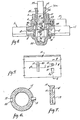
- By way of example, an illustrative embodiment of the invention will now be described with reference to the accompanying drawings, of which:
- Figure 1 is a plan view of a flush latch shown in its locked condition, the keeper being shown in section.
- Figures 2 and 3 are enlarged sectional views taken through 2-2 and 3-3 respectively, with portions shown in elevation.
- Figure 4 is a partial sectional, partial elevational view corresponding to Fig. 3 with parts shown in their unlatched condition.
- Figure 5 is a developed view of a portion of a control sleeve showing the retainer socket therein.
- Figure 6 is an enlarged transverse sectional view of the control sleeve taken through 6-6 of Fig. 5.
- Figure 7 is an enlarged fragmentary longitudinal view of the control sleeve taken through 7-7 of Fig. 5.
- The flush type rotary drive for latches includes a
body 1 having acylindrical recess 2 at its underside intersected by aradial keeper slot 3. Centered with respect to thecylindrical recess 2 and extending upwardly from thebody 1 is anintegral sleeve 4. The extended end of thesleeve 4 is reduced in external diameter, as indicated by 5, and is received in an opening provided inpanel 6 or other mounting member so that the outer extremity of thesleeve 4 is flush therewith. Thebody 1 is provided with a counterbore 7 coaxial with thesleeve 4. The underside of thebody 1 is provided with a bottom cover plate 8 having a radial channel 9 coinciding with theslot 3. - Received in the
recess 2 is ahook type latch 10. As shown in Fig. 1, thelatch 10 includes a journal hub 11, a connectingportion 12 joined to ahook latch arm 13 occupying approximately a half circle and tapering from theradial portion 12 towards its extremity, such that the radius of curvature decreases to a constant radius portion at the extremity labeled I,. - Received in the
sleeve 4 is aninner control sleeve 14 having in its radially outer surface aprimary locking socket 15 and asecondary locking socket 16 spaced inwardly therefrom, an openposition retension socket 17, spaced circumferentially therefrom, their relative positions being shown in Figs. 5, 6 and 7. The axially outward margins ofsocket socket 17, which is in the form of an axial channel, is provided with acircumferential cam face 20. Formed on the body is aradial boss 21 having aradial bore 22 which received apin 23 backed byspring 24, which protrudes through the wall of thesleeve 4 and selectively engages thesockets secondary socket pin 23 is less thanlength 1, of the constant radius portion of thehook latch 13. Accordingly, should thepin 23 not fully engagesocket 15 and become engaged in thesecondary locking socket 16, thecontrol sleeve 14 is prevented from rotating an amount sufficient to allow the device to unlatch. As shown in Fig. 5,secondary latching socket 16 has substantially the same center line assocket 15,socket 16 being slightly displaced in the direction of rotation towardsocket 17. - The upper portion of the inner or
control sleeve 14 is provided with asquare bore 25 which receives asquare closure pin 26. The inner end of thebore 25 terminates in ashoulder 28 and the inner end of theclosure pin 26 is provided with ahead 29 which bears against theshoulder 28. Theclosure pin 26 is provided with a socket, accessible through thehead 29, which receives aspring 30. Thespring 30 receives aguide pin 31 having ahead 32 which engages across bar 33. The ends of thecross bar 33 extend through the walls of thesleeve 14 and are received invertical slots 34 disposed 180° apart and extend upwardly through the upper end of the hook latch hub 11, thereby forming a drive connection between thecontrol sleeve 14 and thehook latch 10. Interposed between thecross bar 33 and the cover plate 8 is aspring 35. - The
radial slot 3 and ahook latch 10 are dimensioned to receive aloop type keeper 36 which, in itself, may be considered as conventional. - Operation of the rotary latch drive is as follows:
- When the
keeper 36 is secured in position by thehook latch 10, the various parts are in the position shown in Figs. 1 and 2. Both thecontrol sleeve 14 and theclosure pin 26 are flush with the upper end of thesleeve 4, and thus flush with the surface of thepanel 6. - To operate the latch, a
polygonal tool 37 is forced into the bore and turned either to withdraw thehook latch 13 from the position shown in Figs. 1 and 2 or to move the hook latch in the opposite direction if the hook latch and keeper are disengaged. When the latch is in its secured position shown in Figs. 1 and 2, thepin 23 is in thesocket 15 held therein by the force of thespring 24. Also the bottom or inner wall of thesocket 15 engages thepin 23 to position the outer face of the control sleeve flush with the surface ofsleeve 4. - In order to initiate movement from the locked condition represented in Figs. 2 and 3, the control sleeve must be pressed inwardly a short distance, in order to remove the
cam pin 23 from thesocket 15. Such inward movement of thecontrol sleeve 14 causes thepin 23 to move radially and axially over thecam face 18. Once disengaged from thesocket 15,latch hook 13 may be readily disengaged as thecam pin 23 rides peripherally on the surface of thecontrol sleeve 14 which is urged by spring force from its flush position and allowed to rise above theouter sleeve 4 until thekeeper 36 is completely disengaged as indicated in Fig. 4 and thepin 23 enters the axially extendedsocket 17, causing thecam pin 23 to detent the latch in its released condition. - The axial extent of the
socket 17 is equal to the full travel of thecontrol sleeve 14 so that irrespective of axial movement of the control sleeve, thepin 23 is retained and the latch remains unlocked. In order to lock the latch, an initial rotating force must be applied to force thepin 23 over thecam surface 20. - Should the
control sleeve 14 become extended, when the latch is locked, the latch remains locked and thepin 23 is received in the lockingsocket 16 until inward force is applied to control sleeve to cause thepin 23 to ride over thecam face 19. The peripheral dimension of thesocket 16 is increased so that thesocket 16 will be engaged even though the latch is not in its fully rotated position. - In order to render the
control sleeve 14 more conspicuous when in its extended position, the outer portion of thesleeve 14 is provided with acircular channel 14a which is given a conspicuous coating. The channel does not come in contact with any surface so that such coating is well protected.
Claims (6)
Applications Claiming Priority (2)
| Application Number | Priority Date | Filing Date | Title |
|---|---|---|---|
| US06/011,193 US4213642A (en) | 1979-02-12 | 1979-02-12 | Rotary latch and method of operation |
| US11193 | 1979-02-12 |
Publications (2)
| Publication Number | Publication Date |
|---|---|
| EP0014794A1 EP0014794A1 (en) | 1980-09-03 |
| EP0014794B1 true EP0014794B1 (en) | 1982-12-01 |
Family
ID=21749255
Family Applications (1)
| Application Number | Title | Priority Date | Filing Date |
|---|---|---|---|
| EP79302035A Expired EP0014794B1 (en) | 1979-02-12 | 1979-09-28 | Rotary latch and method of operation |
Country Status (4)
| Country | Link |
|---|---|
| US (1) | US4213642A (en) |
| EP (1) | EP0014794B1 (en) |
| JP (1) | JPS55107106A (en) |
| DE (1) | DE2964154D1 (en) |
Families Citing this family (8)
| Publication number | Priority date | Publication date | Assignee | Title |
|---|---|---|---|---|
| US4295674A (en) * | 1979-10-01 | 1981-10-20 | Avibank Mfg., Inc. | Latch mechanism |
| US4389062A (en) * | 1980-12-15 | 1983-06-21 | The United States Of America As Represented By The Secretary Of The Navy | Rotary latch |
| US5033696A (en) * | 1989-12-15 | 1991-07-23 | Rockwell International Corporation | Flush mounted hatch opener |
| US5437173A (en) * | 1993-02-18 | 1995-08-01 | Truth Division Of Spx Corporation | Window lock with indicator |
| US20050008458A1 (en) * | 2003-05-30 | 2005-01-13 | Keech Nancy Kay | Biased fastening system |
| US6913297B2 (en) * | 2003-10-27 | 2005-07-05 | Hartwell Corporation | Rotary latch mechanism |
| CN103711371B (en) * | 2013-12-27 | 2016-11-16 | 陕西中航气弹簧有限责任公司 | Double-button dense block |
| US10117356B2 (en) * | 2016-11-28 | 2018-10-30 | Advanced Micro Devices, Inc. | Heat sink connector pin and assembly |
Family Cites Families (7)
| Publication number | Priority date | Publication date | Assignee | Title |
|---|---|---|---|---|
| US2919569A (en) * | 1955-03-30 | 1960-01-05 | Gen Dynamics Corp | Fastening device having a rotatable latch |
| US3254517A (en) * | 1964-03-27 | 1966-06-07 | Camloc Fastener Corp | Rotary latch |
| GB1114909A (en) * | 1965-09-03 | 1968-05-22 | Chicago Lock Co | Nested handle turnbutton door lock assembly |
| GB1175663A (en) * | 1966-01-24 | 1969-12-23 | Regent Lock Company Ltd | Improvements relating to Handle and Lock Combinations |
| US3438227A (en) * | 1966-07-13 | 1969-04-15 | Illinois Lock Co | Pop handle lock |
| US3503642A (en) * | 1968-03-18 | 1970-03-31 | Hartwell Corp | Condition indicator for latches |
| CA1002995A (en) * | 1973-04-27 | 1977-01-04 | Richard L. Moore | Security lock |
-
1979
- 1979-02-12 US US06/011,193 patent/US4213642A/en not_active Expired - Lifetime
- 1979-09-21 JP JP12188979A patent/JPS55107106A/en active Pending
- 1979-09-28 EP EP79302035A patent/EP0014794B1/en not_active Expired
- 1979-09-28 DE DE7979302035T patent/DE2964154D1/en not_active Expired
Also Published As
| Publication number | Publication date |
|---|---|
| US4213642A (en) | 1980-07-22 |
| DE2964154D1 (en) | 1983-01-05 |
| JPS55107106A (en) | 1980-08-16 |
| EP0014794A1 (en) | 1980-09-03 |
Similar Documents
| Publication | Publication Date | Title |
|---|---|---|
| US4773240A (en) | Lock with force-override assembly | |
| EP0675248B2 (en) | Cylinder lock device resistible against unauthorized unlocking | |
| US11773622B2 (en) | Key, lock, and latch assembly | |
| EP0384648B1 (en) | A locking mehanism | |
| US4231240A (en) | Screw plug assembly | |
| US4030321A (en) | Padlock with protected slide bolt and locking means | |
| US5212972A (en) | Tamper resistant pop-handle lock | |
| US5544506A (en) | Auxiliary lock | |
| EP0723488A1 (en) | Cam and wedge-type self-locking mechanism | |
| US4699395A (en) | Universally insertable, rotatable sleeve and cam coupling | |
| US4233913A (en) | Safe door | |
| US4213642A (en) | Rotary latch and method of operation | |
| US4186575A (en) | Trailer hitch ring lock | |
| US6439010B1 (en) | Ring-type meter lock | |
| US6122946A (en) | Key controlled latch | |
| EP0024921B1 (en) | Mountings for keys used in a safety equipment | |
| EP0042310B1 (en) | Catch or lock | |
| US5355703A (en) | Cylindrical lock with cam down retaining tumbler | |
| US20080083253A1 (en) | Door lock assembly with which a door cannot be unlatched by rotating a handle | |
| US4545225A (en) | Latch and lock assembly | |
| GB2068346A (en) | Caps for vehicle filler pipes | |
| EP0014795B1 (en) | Rotary latch | |
| GB1417480A (en) | Disc-pack container | |
| US4854140A (en) | Plunger lock mechanism | |
| US3003803A (en) | Manual safety lock for rear doors |
Legal Events
| Date | Code | Title | Description |
|---|---|---|---|
| PUAI | Public reference made under article 153(3) epc to a published international application that has entered the european phase |
Free format text: ORIGINAL CODE: 0009012 |
|
| AK | Designated contracting states |
Designated state(s): DE FR GB |
|
| DET | De: translation of patent claims | ||
| 17P | Request for examination filed |
Effective date: 19810127 |
|
| GRAA | (expected) grant |
Free format text: ORIGINAL CODE: 0009210 |
|
| AK | Designated contracting states |
Designated state(s): DE FR GB |
|
| REF | Corresponds to: |
Ref document number: 2964154 Country of ref document: DE Date of ref document: 19830105 |
|
| ET | Fr: translation filed | ||
| PGFP | Annual fee paid to national office [announced via postgrant information from national office to epo] |
Ref country code: FR Payment date: 19840920 Year of fee payment: 6 |
|
| PGFP | Annual fee paid to national office [announced via postgrant information from national office to epo] |
Ref country code: DE Payment date: 19841123 Year of fee payment: 6 |
|
| PG25 | Lapsed in a contracting state [announced via postgrant information from national office to epo] |
Ref country code: GB Effective date: 19890928 |
|
| GBPC | Gb: european patent ceased through non-payment of renewal fee | ||
| PG25 | Lapsed in a contracting state [announced via postgrant information from national office to epo] |
Ref country code: FR Effective date: 19900531 |
|
| PG25 | Lapsed in a contracting state [announced via postgrant information from national office to epo] |
Ref country code: DE Effective date: 19900601 |
|
| REG | Reference to a national code |
Ref country code: FR Ref legal event code: ST |
|
| PLBE | No opposition filed within time limit |
Free format text: ORIGINAL CODE: 0009261 |
|
| STAA | Information on the status of an ep patent application or granted ep patent |
Free format text: STATUS: NO OPPOSITION FILED WITHIN TIME LIMIT |