EP0014341B1 - Integral medical electrode and skin preparation device - Google Patents
Integral medical electrode and skin preparation device Download PDFInfo
- Publication number
- EP0014341B1 EP0014341B1 EP80100186A EP80100186A EP0014341B1 EP 0014341 B1 EP0014341 B1 EP 0014341B1 EP 80100186 A EP80100186 A EP 80100186A EP 80100186 A EP80100186 A EP 80100186A EP 0014341 B1 EP0014341 B1 EP 0014341B1
- Authority
- EP
- European Patent Office
- Prior art keywords
- electrode
- skin
- patient
- conductive
- conductive means
- Prior art date
- Legal status (The legal status is an assumption and is not a legal conclusion. Google has not performed a legal analysis and makes no representation as to the accuracy of the status listed.)
- Expired
Links
Images

Classifications
-
- A—HUMAN NECESSITIES
- A61—MEDICAL OR VETERINARY SCIENCE; HYGIENE
- A61B—DIAGNOSIS; SURGERY; IDENTIFICATION
- A61B5/00—Measuring for diagnostic purposes; Identification of persons
- A61B5/24—Detecting, measuring or recording bioelectric or biomagnetic signals of the body or parts thereof
- A61B5/316—Modalities, i.e. specific diagnostic methods
- A61B5/318—Heart-related electrical modalities, e.g. electrocardiography [ECG]
- A61B5/325—Preparing electrode sites, e.g. by abrasion
-
- A—HUMAN NECESSITIES
- A61—MEDICAL OR VETERINARY SCIENCE; HYGIENE
- A61B—DIAGNOSIS; SURGERY; IDENTIFICATION
- A61B5/00—Measuring for diagnostic purposes; Identification of persons
- A61B5/24—Detecting, measuring or recording bioelectric or biomagnetic signals of the body or parts thereof
- A61B5/25—Bioelectric electrodes therefor
- A61B5/251—Means for maintaining electrode contact with the body
- A61B5/257—Means for maintaining electrode contact with the body using adhesive means, e.g. adhesive pads or tapes
-
- A—HUMAN NECESSITIES
- A61—MEDICAL OR VETERINARY SCIENCE; HYGIENE
- A61N—ELECTROTHERAPY; MAGNETOTHERAPY; RADIATION THERAPY; ULTRASOUND THERAPY
- A61N1/00—Electrotherapy; Circuits therefor
- A61N1/02—Details
- A61N1/04—Electrodes
-
- H—ELECTRICITY
- H01—ELECTRIC ELEMENTS
- H01R—ELECTRICALLY-CONDUCTIVE CONNECTIONS; STRUCTURAL ASSOCIATIONS OF A PLURALITY OF MUTUALLY-INSULATED ELECTRICAL CONNECTING ELEMENTS; COUPLING DEVICES; CURRENT COLLECTORS
- H01R4/00—Electrically-conductive connections between two or more conductive members in direct contact, i.e. touching one another; Means for effecting or maintaining such contact; Electrically-conductive connections having two or more spaced connecting locations for conductors and using contact members penetrating insulation
- H01R4/26—Connections in which at least one of the connecting parts has projections which bite into or engage the other connecting part in order to improve the contact
Definitions
- the invention relates to an integral medical electrode and skin preparation device for improving the quality of bipotential event detection by minimizing motion artifact arising from skin potential, the medical electrode including electrically conductive means capable of detecting and transmitting biopotential events for recording, holding means associated with the conductive means securing the electrode to the skin of the patient, and a member contacting the skin and the conductive means when the electrode is secured to the skin.
- Motion artifact can be defined as motion induced fluctuation of skin potential which manifests itself as electrical interference often superimposed on the desired biopotential signal and minimizes its usefulness for diagnostic and clinical purposes.
- Motion artifacts have long been a problem in measurement of bio- potentials, particularly in long-term electrocardiogram (ECG) monitoring of coronary care patients and in exercise (stress) ECG's. They are generally caused by movement of the patient relative to the electrode applied to the patient's skin, thereby disturbing the skin potential and creating extraneous read-outs on the monitor which either mask the desired biopotential signal or cause a shift in the baseline.
- ECG electrocardiogram
- a medical electrode as precedingly described is disclosed in the US-A-4 137 909. Such a medical electrode is suited for cardiac monitoring, however, reliable trace results from such an electrode are highly dependent on adequate skin preparation prior to application of the electrode. Proper skin preparation is time consuming as a regular stress ECG requires 3 to 12, generally 10 electrodes.
- Skin preparation is carried out in various ways. The most common method of preparing the skin is to rub the patient's skin in the areas where the electrodes are to be applied with a gritty material contained in a carrier or to rub the patient's skin with a rough surfaced material to which an alcohol or other solvent is applied. After briskly rubbing the skin, the skin is dried and again rubbed with a dry cloth.
- the malfunctioning electrodes must be identified, removed, the skin again cleaned and the electrodes reapplied to assure an adequate and accurate trace.
- Different skin preparation techniques are employed by different individuals. The effectiveness of the skin preparation depends on the technique used as well as the level of skill of the person preparing the skin. Predictably, skin preparation in this manner is highly variable.
- the present invention solves the task to provide a medical electrode the application of which is less time consuming and with which more reliable, accurate and uniform traces are obtained.
- the surface mounted medical electrode according to the invention is first applied to the skin and then the skin is prepared. After the electrode has been applied to the skin the abrasive member may be moved to penetrate the epidermal layer of the skin.
- An advantage achieved thereby is that thereby motion artifacts are minimized arising from skin potential variations and skin impedance.
- a further advantage obtained by the medical electrode according to the invention is that a more uniform and consistent skin preparation from patient to patient is possible. This is due to an elimination of technique variability in skin preparation.
- the electrode may be either pre-gelled or not pre-gelled and disposable or reusable.
- the conductive means of the electrode may hold the abrasive member which may be provided with an electrolyte.
- the conductive means is secured for movement relative to an adhesive coated sheet member used to adhere the electrode to the skin.
- the electrode When the electrode is pre-gelled and is stored, it may be provided with a removable protective cover for the adhesive coated sheet member and for the abrasive member provided with electrolyte gel.
- a system including the surface mounted medical electrode and a timed applicator for skin preparation, the timed applicator delivering a prescribed amount of skin preparation through the electrode.
- the conductive element of the medical electrode may have a specially designed stud for coupling to a powered applicator gun so that the applicator gun can drive the conductive element even though the applicator may engage the stud at an angle.
- the applicator may be designed as an applicator gun for delivering a prescribed amount of skin preparation through the electrode by means of the abrasive member.
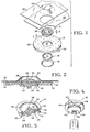
- Fig. 1 illustrates the surface mounted elec- ' trode of this invention which consists of a circular sheet member 10 having an annular cutout portion 12 in the center thereof in which a collar 14 is inserted, the collar holding an electrically conductive member 16 therein.
- a ring 18 may be employed to clamp around the upper portion of the collar 14.
- the sheet member 10 is coated on one side with a skin adhesive layer 20. The adhesive is protected during storage with a protective cover 22.
- An abrasive member 24 (see Fig. 2), provided with an electrolyte gel, is placed in contact with the conductive member 16 and is protected during storage with a protective cover 26.
- the collar 14 has the configuration of an inverted hat having a flat base 28 and a vertical wall 30 normal and integral with the base terminating in a contoured flange 32.
- the base has an annular opening 34 in the center thereof with a diameter less than the diameter of the inner wall 30.
- Around the annular opening 34 is a vertical wall 36 having slots 38 cut therein about every 90 degrees. The function of the slots will be described in detail later.
- the walls 30 and 36 extend above the plane of the base 28 leaving a channel 40 therebetween.
- the holder is generally molded from a semi-flexible plastic material such as an acetate-based material, nylon, polyester, polyethylene or polypropylene.
- the wall 36 is made sufficiently thin so that it can be flexed under pressure.
- the diameter of the collar 14 is substantially greater than its height.
- the inner periphery of the wall 36 is provided with a ridge 42 whose function will be later described.
- the electrically conductive member 16 is adapted to be held by the collar.
- the electrically conductive member may be manufactured from a synthetic resin impregnated with carbon, from a suitable electrically conductive metal or metal-containing material or other suitable electrically conductive material.
- the electrically conductive member 16 includes a lower portion 44 having a textured convex lower surface 45 and a thickness substantially equal to the depth of the cup formed by the flange 32, wall 30 and base 28 of the collar. Integral with the lower portion 44 is an upper portion 46 of reduced diameter relative to the lower portion, the upper portion 46 having a diameter equal to that of the annular opening 34 in the collar.
- the circumference of the upper portion has a slot 48 therein which is interrupted by detents 50 positioned normal to the slot 48.
- the vertical detents are spaced about every 72 degrees around the circumference of the upper portion.
- the conductive member 16 is snapped into place in the collar 14.
- the slot 48 of the conductive member receives the ridge 42 in the wall 36 of the collar to prevent the conductive member from moving vertically within the collar.
- the detents 50 engage in the slots 38 in the flexible wall 36 of the collar to prevent the conductive member from being rotated except by a predetermined torque/force. Application of sufficient torque to the conductive member 16 will cause the conductive member to rotate within the collar, the spacing of the detents 50 and slots 38 yielding a locking position about every 18 degrees.
- Integral with the conductive member 16 is an upstanding stud 52 provided with a polygonal outer surface 54, preferably an eight-sided surface, so that the coupler of the applicator can be drivingly secured over the stud to rotate the conductive member.
- the outer wall of the lower portion 44 of the conductive member 16 is provided with a thin walled extension 58 around the outer periphery thereof, as illustrated in Fig. 2.
- the means for penetrating the epidermal layer of skin may be a separate abrasive member as illustrated, an abrasive member integral with the conductive member such as bristles forming the surface 45 of the conductive member, or other means capable of penetrating the epidermal layer of the skin when moved relative to the skin.
- the abrasive member 24 is a pad incorporating abrasive fibers and preferably having a convexly curved surface 60 and a diameter substantially the same as the diameter of the lower portion 44 is placed in contact with the surface 45 of the conductive member and the flange 58 folded against the edges of the pad to clamp the pad in place.
- the pad preferably has a thickness such that it extends above the plane of the flange 32 of the collar.
- the pad is loaded with electrolyte gel so that when the electrode is applied to the skin, the electrolyte gel makes good electrical contact between the skin and the conductive member 16.
- the assembled collar 14, conductive member 16 and abrasive member 24 are placed in the annular opening 12 of the adhesive coated sheet member 10.
- the adhesive coating 20 contacts the upper surface of the flange 32 of the collar (see Fig. 2) to secure the collar in place relative to the sheet member.
- a snap ring 18 (which may be color coded) may be snapped over the top of the electrode around the wall 3'0 of the collar. The snap ring is held in place by a ridge 62 extending around the outer terminating edge of the wall 30 of the collar.
- the adhesive which coats the sheet member is protected during storage and prior to use by a removable protective paper sheet 22 having a release coating on its face which engages the adhesive coating 20.
- a protective cover 26 may also be provided for the abrasive member when provided with electrolyte gel so that the electrode may be stored in a ready condition for immediate use.
- the cover may take any shape desired.
- the cover illustrated is made of a flat strip of non-conductive plastic sheet material having raised portions 64 which overlie the abrasive member of the electrode.
- the sheet of plastic material is adhered to the removable protective sheet 22 by a suitable adhesive.
- the protective cover may be made of any suitable plastic material such as polyethylene, polyvinyl butyrate, cellulose acetate, etc.
- the electrodes are placed on a strip of protective sheet material 22 in groups of three or more.
- the electrode is peeled from the surface of the protective paper and placed on the skin in the location desired without prior preparation of the skin.
- the protective sheet when peeled away, takes the protective cover for the abrasive member with it.
- the sheet member 10 may have a tab 66 extending beyond the outer periphery of the sheet member so that the person applying the electrodes can grasp the tab and remove the electrode from the protective sheet 22 without touching and compromising the adhesive coated on the underside of the pad.
- the dimensions of the electrode while not particularly critical, are sized for optimum reliability and accurate body placement.
- the diameter of the sheet member surrounding the holder is generally two to three times the diameter of the collar. Sufficient area should be provided for skin contact by the pressure- sensitive adhesive to adequately hold the electrode to the skin of the patient.
- the adhesive used on the sheet member may be any of the commercially available medical grade pressure- sensitive adhesives currently being used on disposable medical electrodes.
- the sheet member may be a microporous material such as Micropore tape sold by the 3M Company or a polyethylene or polyvinyl chloride foamed plastic.
- the foamed sheet member may be perforated with multiple perforations 68 as illustrated in Fig. 1 to allow adequate ventilation of the skin.
- the invention is intended to include other means of providing motion of the means capable of penetrating the epidermal layer of skin relative to the patient's skin to prepare the skin after application of the electrode.
- the invention is further intended to include other configurations of the abrasive member which, when caused to move with respect to the patient's skin, creates abrasion or puncture of the epidermis.
- Figs. 5, 6 and 7 illustrate, respectively, the applicator 70 and electrical block diagrams of the timing/control circuit and charge status indicator circuit for the applicator used to prepare the skin of the patient after application of the electrode thereto.
- the applicator includes a housing 72 within which is mounted an electric motor 74 driven by AC or DC current from a suitable current source.
- the motor illustrated is driven by a rechargeable battery 76 held in place in a quickly disconnectable case 78 which also serves as the handle of the applicator.
- the lower end of the case includes recessed electrical contacts for battery recharging.
- the motor has a shaft 80 to which a coupler is attached.
- Fig. 5 illustrates the coupler in more detail.
- the shaft 80 is provided with a laterally extending pin 82 as illustrated.
- a sleeve 84 having an elongated slot 86 therein slips over the shaft with the pin 82 riding in the slot 86.
- the head 88 of the coupler is integral with the sleeve and includes a polygonal member 90 which drivingly engages the stud member 52 of the electrode.
- a ring 92 slipped over the sleeve of the coupler, engages the pin 82.
- Spring 94 extends between shoulder 96 of the head 88 of the coupler and the ring 92 to bias the coupler in the forward position illustrated in Fig. 5.
- the spring is sized such that when the applicator engages the electrode, it will deliver a prescribed amount of pressure against the skin for adequate skin preparation.
- the coupler is housed within a housing 98 with the wrench end 90 of the coupler protruding to engage the stud of the electrode. Referring to Fig. 5, the wrench end 90 of the applicator engages the stud 52 of the electrode. Sufficient pressure is applied by the operator of the applicator to retract the coupler and allow the terminating edges 100 of the applicator to rest against the electrode. Once engaged, the applicator is timed to deliver a prescribed amount of skin preparation through the electrode. Generally, with the applicator rotating at 500 rpm the time is less than five seconds at an applied pressure of 3.34 N (0.75 lbs). The motor of the applicator is energized by switch 102.
- Fig. 4 illustrates one manner in which the wrench end 90 of the applicator engages the stud 52 of the conductive member for rotation.
- the exterior surface of the stud has an octagonal configuration so that the wrench can drivingly engage the stud at an angle other than normal to the stud. This is important for the person applying the electrodes in that the angle of the applicator relative to the stud is not critical to proper driving engagement of the stud and the applicator.
- the octagonal stud functions in a similar manner to a universal joint allowing the coupler of the applicator to drivingly engage it over a range of angles varying from normal.
- Figs. 6 and 7 schematically illustrate the timing/control circuit for the applicator and the charge/status indicator circuit which indicates to the operator whether the applicator is adequately charged for use.
- the switch 102 of the applicator is pressed to close the circuit from the battery 104 thereby triggering a one-shot 106.
- the one-shot 106 generates a pulse having a duration determined by capacitor 107 and resistor 109.
- the pulse is amplified by a current amplifier 108 and passes through a conventional protection circuit 110 to activate the motor 74 of the applicator.
- the motor 74 rotates for a predetermined duration each time the switch 102 is actuated.
- Fig. 7 illustrates one method of charging the rechargeable batteries 76 of the applicator.
- the charger includes a status indicator circuit which indicates to the operator whether the batteries of the applicator are adequately charged for use.
- Current from a conventional 110 volt AC source is converted to direct current by a transformer and rectifier 112.
- the output from the transformer and rectifier 112 flows through a current regulator 114 by way of filter 116 to the batteries to be charged.
- a current-sensing amplifier 118 senses the current draw of the current regulator 114 and indicates by way of the charge ready indicator 120 and comparator 122 the status of the charge of the battery.
- the current delivered to the barreries is regulated by voltage regulator 124.
- a power-on indicator 126 is provided to tell the operator whether the charge unit is functioning.
- the electrodes When ready for use, the electrodes are peeled away from the protective paper and protective covering and placed on the skin of the patient where desired.
- the applicator is engaged with the stud of the respective electrodes and activated to rotate the conductive element and the abrasive member to abrade the skin in contact with the abrasive member.
- the convex surface of the abrasive member concentrates abrasion of the skin near its center.
- the pressure and time used as well as the abrasive characteristics of the abrasive member are such that the epidermis is not adequately removed to expose nerve endings or capillaries. Penetration of the epidermis may cause skin irritation, particularly if an electrolyte having a high concentration of a soluble salt is used.
- Preparation of the epidermis provided by the electrode and applicator enables use of an electrolyte gel having a salt concentration which is relatively isotonic to minimize gel irritation.
- the sensor for the electrode may be any suitable metal/metal salt combination having low polarization characteristics such as silver/silver chloride.
- a coating 56 of the metal is provided on the planar surface 45 of the conductive member.
- silver it may be desirable to form a layer of silver chloride on the silver layer coated on conductive surface of the conductive member.
- the layer of silver chloride may be formed in various ways. One convenient method is to pass an electric current through the electrolyte soaked abrasive member and conductive member to electrolytically form a layer of silver chloride on the surface of the silver layer.
- the combined use of the electrode and applicator enables a systematized and consistent approach to skin preparation and electrode application.
- the extensive preparation of the skin of a patient prior to application of surface mounted electrodes of the prior art is not necessary with the electrode of this invention. Skin preparation is uniformly performed after the electrode is applied.
Landscapes
- Health & Medical Sciences (AREA)
- Life Sciences & Earth Sciences (AREA)
- Animal Behavior & Ethology (AREA)
- Veterinary Medicine (AREA)
- Public Health (AREA)
- Engineering & Computer Science (AREA)
- Biomedical Technology (AREA)
- General Health & Medical Sciences (AREA)
- Surgery (AREA)
- Molecular Biology (AREA)
- Physics & Mathematics (AREA)
- Medical Informatics (AREA)
- Heart & Thoracic Surgery (AREA)
- Pathology (AREA)
- Biophysics (AREA)
- Cardiology (AREA)
- Nuclear Medicine, Radiotherapy & Molecular Imaging (AREA)
- Radiology & Medical Imaging (AREA)
- Electrotherapy Devices (AREA)
- Measurement And Recording Of Electrical Phenomena And Electrical Characteristics Of The Living Body (AREA)
Description
- The invention relates to an integral medical electrode and skin preparation device for improving the quality of bipotential event detection by minimizing motion artifact arising from skin potential, the medical electrode including electrically conductive means capable of detecting and transmitting biopotential events for recording, holding means associated with the conductive means securing the electrode to the skin of the patient, and a member contacting the skin and the conductive means when the electrode is secured to the skin.
- Motion artifact can be defined as motion induced fluctuation of skin potential which manifests itself as electrical interference often superimposed on the desired biopotential signal and minimizes its usefulness for diagnostic and clinical purposes. Motion artifacts have long been a problem in measurement of bio- potentials, particularly in long-term electrocardiogram (ECG) monitoring of coronary care patients and in exercise (stress) ECG's. They are generally caused by movement of the patient relative to the electrode applied to the patient's skin, thereby disturbing the skin potential and creating extraneous read-outs on the monitor which either mask the desired biopotential signal or cause a shift in the baseline.
- It is known that light abrasion of the skin reduced the skin potential as well as minimizes the skin impedance and thereby reduces motion artifacts and improves trace quality. Tam, Hak W., et al., "Minimizing Electrode Motion Artifact by Skin Abrason", IEEE Trans. on Biomed. Engr., BME-24, No. 2, pp. 134-137 (March 1977).
- A medical electrode as precedingly described is disclosed in the US-A-4 137 909. Such a medical electrode is suited for cardiac monitoring, however, reliable trace results from such an electrode are highly dependent on adequate skin preparation prior to application of the electrode. Proper skin preparation is time consuming as a regular stress ECG requires 3 to 12, generally 10 electrodes. Skin preparation is carried out in various ways. The most common method of preparing the skin is to rub the patient's skin in the areas where the electrodes are to be applied with a gritty material contained in a carrier or to rub the patient's skin with a rough surfaced material to which an alcohol or other solvent is applied. After briskly rubbing the skin, the skin is dried and again rubbed with a dry cloth. If, after the electrodes are applied, a proper trace is not obtained from one or more of the electrodes, the malfunctioning electrodes must be identified, removed, the skin again cleaned and the electrodes reapplied to assure an adequate and accurate trace. Different skin preparation techniques are employed by different individuals. The effectiveness of the skin preparation depends on the technique used as well as the level of skill of the person preparing the skin. Predictably, skin preparation in this manner is highly variable.
- The present invention, as characterized by the claims, solves the task to provide a medical electrode the application of which is less time consuming and with which more reliable, accurate and uniform traces are obtained.
- The surface mounted medical electrode according to the invention is first applied to the skin and then the skin is prepared. After the electrode has been applied to the skin the abrasive member may be moved to penetrate the epidermal layer of the skin. An advantage achieved thereby is that thereby motion artifacts are minimized arising from skin potential variations and skin impedance. A further advantage obtained by the medical electrode according to the invention is that a more uniform and consistent skin preparation from patient to patient is possible. This is due to an elimination of technique variability in skin preparation.
- The electrode may be either pre-gelled or not pre-gelled and disposable or reusable. The conductive means of the electrode may hold the abrasive member which may be provided with an electrolyte. The conductive means is secured for movement relative to an adhesive coated sheet member used to adhere the electrode to the skin. When the electrode is pre-gelled and is stored, it may be provided with a removable protective cover for the adhesive coated sheet member and for the abrasive member provided with electrolyte gel.
- According to a further aspect of the invention a system may be provided, including the surface mounted medical electrode and a timed applicator for skin preparation, the timed applicator delivering a prescribed amount of skin preparation through the electrode.
- According to another aspect of the invention the conductive element of the medical electrode may have a specially designed stud for coupling to a powered applicator gun so that the applicator gun can drive the conductive element even though the applicator may engage the stud at an angle. The applicator may be designed as an applicator gun for delivering a prescribed amount of skin preparation through the electrode by means of the abrasive member.
- After having described substantial advantages obtained by the present invention, the present invention will now be explained in connection with an embodiment and reference to the drawings.
-
- Fig. 1 is an exploded view of a surface mounted medical electrode of this invention, illustrating the components which make up the electrode except for the abrasive electrolyte- containing member.
- Fig. 2 is a vertical cross-section of the electrode of Fig. 1.
- Fig. 3 is a perspective view of the conductive element and collar of the electrode of Fig. 1 illustrating the detent in the conductive element and notch arrangement of the collar for securing the conductive member against rotation when rotation is not desired.
- Fig. 4 is a perspective view of the projecting stud of the conductive member of the electrode of Fig. 1 and the coupler of the applicator gun illustrating the manner in which the applicator is connected to the stud for rotation of the conductive member by the applicator.
- Fig. 5 is a schematic view of the applicator used to drive the movable conductive element and abrasive member of the electrode to perform skin preparation.
- Fig. 6 is a block diagram of the timing control circuit of the applicator.
- Fig. 7 is a block diagram of the charge status indicator circuit of the applicator.
- Fig. 1 illustrates the surface mounted elec- ' trode of this invention which consists of a
circular sheet member 10 having anannular cutout portion 12 in the center thereof in which acollar 14 is inserted, the collar holding an electricallyconductive member 16 therein. Aring 18 may be employed to clamp around the upper portion of thecollar 14. Thesheet member 10 is coated on one side with a skinadhesive layer 20. The adhesive is protected during storage with aprotective cover 22. An abrasive member 24 (see Fig. 2), provided with an electrolyte gel, is placed in contact with theconductive member 16 and is protected during storage with aprotective cover 26. - The
collar 14 has the configuration of an inverted hat having aflat base 28 and avertical wall 30 normal and integral with the base terminating in acontoured flange 32. The base has anannular opening 34 in the center thereof with a diameter less than the diameter of theinner wall 30. Around theannular opening 34, is avertical wall 36 havingslots 38 cut therein about every 90 degrees. The function of the slots will be described in detail later. Thewalls base 28 leaving achannel 40 therebetween. The holder is generally molded from a semi-flexible plastic material such as an acetate-based material, nylon, polyester, polyethylene or polypropylene. Thewall 36 is made sufficiently thin so that it can be flexed under pressure. The diameter of thecollar 14 is substantially greater than its height. The inner periphery of thewall 36 is provided with aridge 42 whose function will be later described. - The electrically
conductive member 16 is adapted to be held by the collar. The electrically conductive member may be manufactured from a synthetic resin impregnated with carbon, from a suitable electrically conductive metal or metal-containing material or other suitable electrically conductive material. The electricallyconductive member 16 includes alower portion 44 having a textured convexlower surface 45 and a thickness substantially equal to the depth of the cup formed by theflange 32,wall 30 andbase 28 of the collar. Integral with thelower portion 44 is anupper portion 46 of reduced diameter relative to the lower portion, theupper portion 46 having a diameter equal to that of theannular opening 34 in the collar. The circumference of the upper portion has aslot 48 therein which is interrupted bydetents 50 positioned normal to theslot 48. The vertical detents are spaced about every 72 degrees around the circumference of the upper portion. Theconductive member 16 is snapped into place in thecollar 14. Theslot 48 of the conductive member receives theridge 42 in thewall 36 of the collar to prevent the conductive member from moving vertically within the collar. Thedetents 50 engage in theslots 38 in theflexible wall 36 of the collar to prevent the conductive member from being rotated except by a predetermined torque/force. Application of sufficient torque to theconductive member 16 will cause the conductive member to rotate within the collar, the spacing of thedetents 50 andslots 38 yielding a locking position about every 18 degrees. - Integral with the
conductive member 16 is anupstanding stud 52 provided with a polygonalouter surface 54, preferably an eight-sided surface, so that the coupler of the applicator can be drivingly secured over the stud to rotate the conductive member. - The outer wall of the
lower portion 44 of theconductive member 16 is provided with a thinwalled extension 58 around the outer periphery thereof, as illustrated in Fig. 2. - The means for penetrating the epidermal layer of skin may be a separate abrasive member as illustrated, an abrasive member integral with the conductive member such as bristles forming the
surface 45 of the conductive member, or other means capable of penetrating the epidermal layer of the skin when moved relative to the skin. Theabrasive member 24 is a pad incorporating abrasive fibers and preferably having a convexlycurved surface 60 and a diameter substantially the same as the diameter of thelower portion 44 is placed in contact with thesurface 45 of the conductive member and theflange 58 folded against the edges of the pad to clamp the pad in place. The pad preferably has a thickness such that it extends above the plane of theflange 32 of the collar. The pad is loaded with electrolyte gel so that when the electrode is applied to the skin, the electrolyte gel makes good electrical contact between the skin and theconductive member 16. - The assembled
collar 14,conductive member 16 andabrasive member 24 are placed in theannular opening 12 of the adhesivecoated sheet member 10. Theadhesive coating 20 contacts the upper surface of theflange 32 of the collar (see Fig. 2) to secure the collar in place relative to the sheet member. A snap ring 18 (which may be color coded) may be snapped over the top of the electrode around the wall 3'0 of the collar. The snap ring is held in place by aridge 62 extending around the outer terminating edge of thewall 30 of the collar. - The adhesive which coats the sheet member is protected during storage and prior to use by a removable
protective paper sheet 22 having a release coating on its face which engages theadhesive coating 20. Aprotective cover 26 may also be provided for the abrasive member when provided with electrolyte gel so that the electrode may be stored in a ready condition for immediate use. The cover may take any shape desired. The cover illustrated is made of a flat strip of non-conductive plastic sheet material having raisedportions 64 which overlie the abrasive member of the electrode. The sheet of plastic material is adhered to the removableprotective sheet 22 by a suitable adhesive. The protective cover may be made of any suitable plastic material such as polyethylene, polyvinyl butyrate, cellulose acetate, etc. After the electrodes are assembled with the protective covering they may be stored for indefinite periods of time until needed. Preferably, the electrode is packaged in an air and water tight package to avoid dehydration of the electrode gel during storage. Such packaging is conventionally used. - Generally, the electrodes are placed on a strip of
protective sheet material 22 in groups of three or more. When the electrodes are ready to be used, the electrode is peeled from the surface of the protective paper and placed on the skin in the location desired without prior preparation of the skin. The protective sheet, when peeled away, takes the protective cover for the abrasive member with it. If desired, thesheet member 10 may have atab 66 extending beyond the outer periphery of the sheet member so that the person applying the electrodes can grasp the tab and remove the electrode from theprotective sheet 22 without touching and compromising the adhesive coated on the underside of the pad. - The dimensions of the electrode, while not particularly critical, are sized for optimum reliability and accurate body placement. The diameter of the sheet member surrounding the holder is generally two to three times the diameter of the collar. Sufficient area should be provided for skin contact by the pressure- sensitive adhesive to adequately hold the electrode to the skin of the patient. The adhesive used on the sheet member may be any of the commercially available medical grade pressure- sensitive adhesives currently being used on disposable medical electrodes. The sheet member may be a microporous material such as Micropore tape sold by the 3M Company or a polyethylene or polyvinyl chloride foamed plastic. The foamed sheet member may be perforated with multiple perforations 68 as illustrated in Fig. 1 to allow adequate ventilation of the skin.
- While the preferred embodiment of the electrode described above abrades the skin by rotation of the conductive member and abrasive member after the electrode is adhered to the skin, the invention is intended to include other means of providing motion of the means capable of penetrating the epidermal layer of skin relative to the patient's skin to prepare the skin after application of the electrode. The invention is further intended to include other configurations of the abrasive member which, when caused to move with respect to the patient's skin, creates abrasion or puncture of the epidermis.
- Figs. 5, 6 and 7 illustrate, respectively, the
applicator 70 and electrical block diagrams of the timing/control circuit and charge status indicator circuit for the applicator used to prepare the skin of the patient after application of the electrode thereto. Referring to Fig. 5, the applicator includes ahousing 72 within which is mounted anelectric motor 74 driven by AC or DC current from a suitable current source. The motor illustrated is driven by arechargeable battery 76 held in place in a quicklydisconnectable case 78 which also serves as the handle of the applicator. The lower end of the case includes recessed electrical contacts for battery recharging. The motor has ashaft 80 to which a coupler is attached. - Fig. 5 illustrates the coupler in more detail. The
shaft 80 is provided with a laterally extendingpin 82 as illustrated. Asleeve 84 having anelongated slot 86 therein slips over the shaft with thepin 82 riding in theslot 86. Thehead 88 of the coupler is integral with the sleeve and includes apolygonal member 90 which drivingly engages thestud member 52 of the electrode. Aring 92, slipped over the sleeve of the coupler, engages thepin 82.Spring 94 extends betweenshoulder 96 of thehead 88 of the coupler and thering 92 to bias the coupler in the forward position illustrated in Fig. 5. The spring is sized such that when the applicator engages the electrode, it will deliver a prescribed amount of pressure against the skin for adequate skin preparation. The coupler is housed within ahousing 98 with thewrench end 90 of the coupler protruding to engage the stud of the electrode. Referring to Fig. 5, thewrench end 90 of the applicator engages thestud 52 of the electrode. Sufficient pressure is applied by the operator of the applicator to retract the coupler and allow the terminatingedges 100 of the applicator to rest against the electrode. Once engaged, the applicator is timed to deliver a prescribed amount of skin preparation through the electrode. Generally, with the applicator rotating at 500 rpm the time is less than five seconds at an applied pressure of 3.34 N (0.75 lbs). The motor of the applicator is energized byswitch 102. - Fig. 4 illustrates one manner in which the
wrench end 90 of the applicator engages thestud 52 of the conductive member for rotation. The exterior surface of the stud has an octagonal configuration so that the wrench can drivingly engage the stud at an angle other than normal to the stud. This is important for the person applying the electrodes in that the angle of the applicator relative to the stud is not critical to proper driving engagement of the stud and the applicator. The octagonal stud functions in a similar manner to a universal joint allowing the coupler of the applicator to drivingly engage it over a range of angles varying from normal. - Figs. 6 and 7 schematically illustrate the timing/control circuit for the applicator and the charge/status indicator circuit which indicates to the operator whether the applicator is adequately charged for use. Referring to Fig. 6, the
switch 102 of the applicator is pressed to close the circuit from thebattery 104 thereby triggering a one-shot 106. The one-shot 106 generates a pulse having a duration determined bycapacitor 107 andresistor 109. The pulse is amplified by acurrent amplifier 108 and passes through aconventional protection circuit 110 to activate themotor 74 of the applicator. Thus, themotor 74 rotates for a predetermined duration each time theswitch 102 is actuated. - Fig. 7 illustrates one method of charging the
rechargeable batteries 76 of the applicator. The charger includes a status indicator circuit which indicates to the operator whether the batteries of the applicator are adequately charged for use. Current from a conventional 110 volt AC source is converted to direct current by a transformer andrectifier 112. The output from the transformer andrectifier 112 flows through acurrent regulator 114 by way offilter 116 to the batteries to be charged. A current-sensingamplifier 118 senses the current draw of thecurrent regulator 114 and indicates by way of the chargeready indicator 120 andcomparator 122 the status of the charge of the battery. The current delivered to the barreries is regulated byvoltage regulator 124. A power-onindicator 126 is provided to tell the operator whether the charge unit is functioning. - When ready for use, the electrodes are peeled away from the protective paper and protective covering and placed on the skin of the patient where desired. The applicator is engaged with the stud of the respective electrodes and activated to rotate the conductive element and the abrasive member to abrade the skin in contact with the abrasive member. The convex surface of the abrasive member concentrates abrasion of the skin near its center. The pressure and time used as well as the abrasive characteristics of the abrasive member are such that the epidermis is not adequately removed to expose nerve endings or capillaries. Penetration of the epidermis may cause skin irritation, particularly if an electrolyte having a high concentration of a soluble salt is used. Preparation of the epidermis provided by the electrode and applicator enables use of an electrolyte gel having a salt concentration which is relatively isotonic to minimize gel irritation.
- The sensor for the electrode may be any suitable metal/metal salt combination having low polarization characteristics such as silver/silver chloride. A
coating 56 of the metal is provided on theplanar surface 45 of the conductive member. When silver is used, it may be desirable to form a layer of silver chloride on the silver layer coated on conductive surface of the conductive member. The layer of silver chloride may be formed in various ways. One convenient method is to pass an electric current through the electrolyte soaked abrasive member and conductive member to electrolytically form a layer of silver chloride on the surface of the silver layer. - The combined use of the electrode and applicator enables a systematized and consistent approach to skin preparation and electrode application. The extensive preparation of the skin of a patient prior to application of surface mounted electrodes of the prior art is not necessary with the electrode of this invention. Skin preparation is uniformly performed after the electrode is applied.
Claims (13)
Applications Claiming Priority (2)
| Application Number | Priority Date | Filing Date | Title |
|---|---|---|---|
| US3109 | 1979-01-15 | ||
| US06/003,109 US4311152A (en) | 1979-01-15 | 1979-01-15 | Medical electrode and system for minimizing motion artifacts |
Publications (2)
| Publication Number | Publication Date |
|---|---|
| EP0014341A1 EP0014341A1 (en) | 1980-08-20 |
| EP0014341B1 true EP0014341B1 (en) | 1983-06-15 |
Family
ID=21704201
Family Applications (1)
| Application Number | Title | Priority Date | Filing Date |
|---|---|---|---|
| EP80100186A Expired EP0014341B1 (en) | 1979-01-15 | 1980-01-15 | Integral medical electrode and skin preparation device |
Country Status (4)
| Country | Link |
|---|---|
| US (1) | US4311152A (en) |
| EP (1) | EP0014341B1 (en) |
| JP (1) | JPS55108341A (en) |
| DE (1) | DE3063713D1 (en) |
Families Citing this family (36)
| Publication number | Priority date | Publication date | Assignee | Title |
|---|---|---|---|---|
| US4274419A (en) * | 1979-10-19 | 1981-06-23 | Quinton Instrument Co. | Skin preparation device and method used in the application of medical electrodes |
| US4444194A (en) * | 1982-03-08 | 1984-04-24 | Ndm Corporation | Medical electrode assembly |
| US4490005A (en) * | 1982-06-21 | 1984-12-25 | Minnesota Mining And Manufacturing Company | Electrical connector |
| JPS5993405U (en) * | 1982-12-07 | 1984-06-25 | 日本光電工業株式会社 | Biological electrode |
| US4538612A (en) * | 1983-08-29 | 1985-09-03 | Ndm Corporation | Skin preparation method and product |
| USD295784S (en) | 1985-09-20 | 1988-05-17 | Fukuda Denshi Co., Ltd. | Electrode pad for an electrocardiograph |
| US4995392A (en) * | 1988-12-29 | 1991-02-26 | Westinghouse Electric Corp. | Self-preparing electrode with removable plastic abrading brush |
| US5660177A (en) * | 1991-11-04 | 1997-08-26 | Biofield Corp. | D.C. biopotential sensing electrode assemblies for apparatus for disease, injury and bodily condition screening or sensing |
| US5309909A (en) * | 1992-05-22 | 1994-05-10 | Physio-Control Corporation | Combined skin preparation and monitoring electrode |
| US5261402A (en) * | 1992-07-20 | 1993-11-16 | Graphic Controls Corporation | Snapless, tabless, disposable medical electrode with low profile |
| US5305746A (en) * | 1992-09-29 | 1994-04-26 | Aspect Medical Systems, Inc. | Disposable, pre-gelled, self-prepping electrode |
| US5746207A (en) * | 1993-03-23 | 1998-05-05 | Mclaughlin; James Andrew | Profiled biosignal electrode device |
| US5458141A (en) * | 1993-08-04 | 1995-10-17 | Quinton Instrument Company | Abrasive skin electrode |
| USD357069S (en) | 1993-08-25 | 1995-04-04 | Quinton Instrument Company | Medical electrode |
| FR2733898A1 (en) * | 1995-05-10 | 1996-11-15 | Comepa Sa | ELECTRODE SUITABLE FOR APPLICATION ON THE SKIN OF A LIVING BEING |
| US5645063A (en) * | 1995-06-05 | 1997-07-08 | Quinton Instrument Company | Skin electrode having multiple conductive center members |
| US5813404A (en) | 1995-10-20 | 1998-09-29 | Aspect Medical Systems, Inc. | Electrode connector system |
| US5740812A (en) * | 1996-01-25 | 1998-04-21 | Mindwaves, Ltd. | Apparatus for and method of providing brainwave biofeedback |
| US5983129A (en) * | 1998-02-19 | 1999-11-09 | Cowan; Jonathan D. | Method for determining an individual's intensity of focused attention and integrating same into computer program |
| US6690959B2 (en) | 2000-09-01 | 2004-02-10 | Medtronic, Inc. | Skin-mounted electrodes with nano spikes |
| US6912414B2 (en) * | 2002-01-29 | 2005-06-28 | Southwest Research Institute | Electrode systems and methods for reducing motion artifact |
| US6711427B1 (en) | 2002-02-13 | 2004-03-23 | Milwaukee Electronics Corporation | Skin abrading medical electrode mounting and packaging system |
| CN100482296C (en) * | 2002-12-19 | 2009-04-29 | 皇家飞利浦电子股份有限公司 | An electrode assembly and a system with impedance control |
| FI20055366A0 (en) * | 2005-06-30 | 2005-06-30 | Gen Electric | An electrode for obtaining a biopotential signal |
| JP2007068550A (en) * | 2005-09-02 | 2007-03-22 | Olympus Medical Systems Corp | Medical equipment |
| WO2007120505A1 (en) | 2006-03-31 | 2007-10-25 | C. R. Bard, Inc. | Catheter including arcuate transition region |
| US8406843B2 (en) * | 2008-04-04 | 2013-03-26 | Mark Tiegs | ECG monitoring electrode |
| JP5803186B2 (en) * | 2011-03-23 | 2015-11-04 | ソニー株式会社 | Biological signal detection electrode and biological signal detection apparatus |
| US20130085368A1 (en) * | 2011-09-30 | 2013-04-04 | Tyco Healthcare Group Lp | Radiolucent ECG Electrode And Method Of Making Same |
| US8929980B2 (en) | 2012-05-03 | 2015-01-06 | Physio-Control, Inc. | External defibrillator electrode, method and system for reducing ECG artifact |
| FI124657B (en) * | 2012-12-31 | 2014-11-28 | Suunto Oy | Male connector for telemetric receiver |
| US10252023B2 (en) | 2013-01-11 | 2019-04-09 | C. R. Bard, Inc. | Curved catheter and methods for making same |
| EP3013212A4 (en) | 2013-06-26 | 2017-10-25 | Sensible Medical Innovations Ltd. | Controlling electromagnetic (em) transmission based on pressure parameters |
| US9480412B1 (en) * | 2013-08-21 | 2016-11-01 | Rhythmlink International Llc | Disposable electrode assembly |
| US11147465B2 (en) | 2015-05-05 | 2021-10-19 | Welch Allyn, Inc. | Abrasive electrode |
| CN113855041B (en) * | 2021-09-14 | 2024-09-17 | 浙江智柔科技有限公司 | Skin treatment method, skin treatment device, and storage medium |
Family Cites Families (16)
| Publication number | Priority date | Publication date | Assignee | Title |
|---|---|---|---|---|
| FR1126748A (en) * | 1955-06-27 | 1956-11-29 | D Electro Mecanique Soc Ind | Lockable pressure screw |
| US2782786A (en) * | 1955-10-10 | 1957-02-26 | Louis R Krasno | Electrocardiograph electrode with absorbent contact surface |
| US2887112A (en) * | 1957-08-15 | 1959-05-19 | Sanborn Company | Pad for skin preparation for electrocardiography and the like |
| DE1566139C3 (en) * | 1967-06-02 | 1975-03-06 | Hermann Prof. Dr.Med. 440 Muenster Poteine | Medical device » |
| US3602216A (en) * | 1969-09-16 | 1971-08-31 | United Aircraft Corp | Paste dispensing body electrode |
| US3750650A (en) * | 1970-12-15 | 1973-08-07 | Hewlett Packard Gmbh | Double spiral electrode for intra-cavity attachment |
| US3776228A (en) * | 1971-09-20 | 1973-12-04 | H Semler | Portable self-contained electrical cardiometric device with three fixed-position nonuniformly spaced input probes |
| US3774592A (en) * | 1971-12-16 | 1973-11-27 | Xerox Corp | Method for providing an improved body electrode electrical connection |
| US3911906A (en) * | 1974-04-24 | 1975-10-14 | Survival Technology | Dry applied and operably dry electrode device |
| US3862633A (en) * | 1974-05-06 | 1975-01-28 | Kenneth C Allison | Electrode |
| US4004578A (en) * | 1974-09-10 | 1977-01-25 | Salve S.A. | Expendable electro-cardiograph electrode |
| US4027664A (en) * | 1975-11-17 | 1977-06-07 | Baxter Travenol Laboratories, Inc. | Diagnostic electrode assembly with a skin preparation surface |
| US4126126A (en) * | 1976-07-27 | 1978-11-21 | C. R. Bard, Inc. | Non-metallic pregelled electrode |
| GB1594214A (en) * | 1977-01-21 | 1981-07-30 | Cardio Tech | Body electrodes |
| US4137909A (en) * | 1977-08-01 | 1979-02-06 | Ndm Corporation | Medical electrode |
| US4180080A (en) * | 1977-10-03 | 1979-12-25 | Hewlett-Packard Company | Electrode assembly for sensing heart activity |
-
1979
- 1979-01-15 US US06/003,109 patent/US4311152A/en not_active Expired - Lifetime
-
1980
- 1980-01-14 JP JP299480A patent/JPS55108341A/en active Granted
- 1980-01-15 DE DE8080100186T patent/DE3063713D1/en not_active Expired
- 1980-01-15 EP EP80100186A patent/EP0014341B1/en not_active Expired
Also Published As
| Publication number | Publication date |
|---|---|
| JPS55108341A (en) | 1980-08-20 |
| EP0014341A1 (en) | 1980-08-20 |
| JPH0146143B2 (en) | 1989-10-06 |
| US4311152A (en) | 1982-01-19 |
| DE3063713D1 (en) | 1983-07-21 |
Similar Documents
| Publication | Publication Date | Title |
|---|---|---|
| US4311152A (en) | Medical electrode and system for minimizing motion artifacts | |
| CA1147395A (en) | Medical electrode and system for minimizing motion artifacts | |
| US5458141A (en) | Abrasive skin electrode | |
| US5645063A (en) | Skin electrode having multiple conductive center members | |
| US5309909A (en) | Combined skin preparation and monitoring electrode | |
| US11219399B1 (en) | Electrode kit for easy and fast deployment in electroencephalogram acquisition and monitoring applications | |
| KR910005881Y1 (en) | Induction electrode for living body | |
| US5261402A (en) | Snapless, tabless, disposable medical electrode with low profile | |
| US5150708A (en) | Tabbed defibrillator electrode pad | |
| EP0618781B1 (en) | Monitoring electrode and self-prepping layer of gel for use with a monitoring electrode | |
| EP0027974A1 (en) | Skin preparation device for the application of medical electrodes | |
| US4936306A (en) | Device and method for monitoring evoked potentials and electroencephalograms | |
| GB1567961A (en) | Nonmetallic pregelled medical electrode | |
| CA1335602C (en) | Electrode having lead wire attachment | |
| CA1264818A (en) | Multipolar medical electrode | |
| US11872045B1 (en) | Physiological recording device with novel and proprietary connector | |
| AU2025205320A1 (en) | Electrode assembly and methods | |
| US11147465B2 (en) | Abrasive electrode | |
| JPH0215443Y2 (en) | ||
| US20230172523A1 (en) | Electrode kit for easy and fast deployment in electroencephalogram acquisition and monitoring applications | |
| JPH0215442Y2 (en) | ||
| EP4329612B1 (en) | Medical electrode | |
| JP2025056909A (en) | Biometric information detection device | |
| JPH0330082Y2 (en) | ||
| JPH0330083Y2 (en) |
Legal Events
| Date | Code | Title | Description |
|---|---|---|---|
| PUAI | Public reference made under article 153(3) epc to a published international application that has entered the european phase |
Free format text: ORIGINAL CODE: 0009012 |
|
| AK | Designated contracting states |
Designated state(s): DE FR GB IT SE |
|
| 17P | Request for examination filed |
Effective date: 19810213 |
|
| ITF | It: translation for a ep patent filed | ||
| GRAA | (expected) grant |
Free format text: ORIGINAL CODE: 0009210 |
|
| AK | Designated contracting states |
Designated state(s): DE FR GB IT SE |
|
| REF | Corresponds to: |
Ref document number: 3063713 Country of ref document: DE Date of ref document: 19830721 |
|
| ET | Fr: translation filed | ||
| PLBE | No opposition filed within time limit |
Free format text: ORIGINAL CODE: 0009261 |
|
| STAA | Information on the status of an ep patent application or granted ep patent |
Free format text: STATUS: NO OPPOSITION FILED WITHIN TIME LIMIT |
|
| 26N | No opposition filed | ||
| REG | Reference to a national code |
Ref country code: FR Ref legal event code: TP |
|
| ITPR | It: changes in ownership of a european patent |
Owner name: FUSIONI;ROBINS MERGING INC. |
|
| ITTA | It: last paid annual fee | ||
| EAL | Se: european patent in force in sweden |
Ref document number: 80100186.8 |
|
| PGFP | Annual fee paid to national office [announced via postgrant information from national office to epo] |
Ref country code: GB Payment date: 19981015 Year of fee payment: 20 |
|
| PGFP | Annual fee paid to national office [announced via postgrant information from national office to epo] |
Ref country code: FR Payment date: 19990111 Year of fee payment: 20 |
|
| PGFP | Annual fee paid to national office [announced via postgrant information from national office to epo] |
Ref country code: SE Payment date: 19990118 Year of fee payment: 20 |
|
| PGFP | Annual fee paid to national office [announced via postgrant information from national office to epo] |
Ref country code: DE Payment date: 19990125 Year of fee payment: 20 |
|
| PG25 | Lapsed in a contracting state [announced via postgrant information from national office to epo] |
Ref country code: GB Free format text: LAPSE BECAUSE OF EXPIRATION OF PROTECTION Effective date: 20000114 |
|
| PG25 | Lapsed in a contracting state [announced via postgrant information from national office to epo] |
Ref country code: SE Free format text: THE PATENT HAS BEEN ANNULLED BY A DECISION OF A NATIONAL AUTHORITY Effective date: 20000130 |
|
| REG | Reference to a national code |
Ref country code: GB Ref legal event code: PE20 Effective date: 20000114 |
|
| EUG | Se: european patent has lapsed |
Ref document number: 80100186.8 |