EP0014227B1 - System and method of reproducing and erasing information - Google Patents
System and method of reproducing and erasing information Download PDFInfo
- Publication number
- EP0014227B1 EP0014227B1 EP79103628A EP79103628A EP0014227B1 EP 0014227 B1 EP0014227 B1 EP 0014227B1 EP 79103628 A EP79103628 A EP 79103628A EP 79103628 A EP79103628 A EP 79103628A EP 0014227 B1 EP0014227 B1 EP 0014227B1
- Authority
- EP
- European Patent Office
- Prior art keywords
- film
- light
- light beam
- recorded
- reflection
- Prior art date
- Legal status (The legal status is an assumption and is not a legal conclusion. Google has not performed a legal analysis and makes no representation as to the accuracy of the status listed.)
- Expired
Links
- 238000000034 method Methods 0.000 title claims description 10
- 238000010521 absorption reaction Methods 0.000 claims description 19
- 239000000758 substrate Substances 0.000 claims description 17
- 230000003287 optical effect Effects 0.000 claims description 7
- 230000031700 light absorption Effects 0.000 claims description 4
- 230000003247 decreasing effect Effects 0.000 claims description 2
- 230000002463 transducing effect Effects 0.000 claims description 2
- 230000001747 exhibiting effect Effects 0.000 claims 6
- 238000010408 sweeping Methods 0.000 claims 1
- 230000007704 transition Effects 0.000 claims 1
- 238000002834 transmittance Methods 0.000 claims 1
- 239000010409 thin film Substances 0.000 description 67
- 239000010408 film Substances 0.000 description 34
- 229910052782 aluminium Inorganic materials 0.000 description 4
- XAGFODPZIPBFFR-UHFFFAOYSA-N aluminium Chemical compound [Al] XAGFODPZIPBFFR-UHFFFAOYSA-N 0.000 description 4
- 150000001875 compounds Chemical class 0.000 description 4
- 230000000694 effects Effects 0.000 description 4
- 230000001678 irradiating effect Effects 0.000 description 4
- 239000011347 resin Substances 0.000 description 4
- 229920005989 resin Polymers 0.000 description 4
- -1 acryl Chemical group 0.000 description 3
- 230000005540 biological transmission Effects 0.000 description 3
- 238000001514 detection method Methods 0.000 description 2
- 239000011521 glass Substances 0.000 description 2
- 239000000463 material Substances 0.000 description 2
- 229910052751 metal Inorganic materials 0.000 description 2
- 239000002184 metal Substances 0.000 description 2
- 229920003023 plastic Polymers 0.000 description 2
- 239000002985 plastic film Substances 0.000 description 2
- 239000004065 semiconductor Substances 0.000 description 2
- 239000007787 solid Substances 0.000 description 2
- 239000006104 solid solution Substances 0.000 description 2
- 238000007740 vapor deposition Methods 0.000 description 2
- BZHJMEDXRYGGRV-UHFFFAOYSA-N Vinyl chloride Chemical compound ClC=C BZHJMEDXRYGGRV-UHFFFAOYSA-N 0.000 description 1
- 230000008033 biological extinction Effects 0.000 description 1
- 239000011248 coating agent Substances 0.000 description 1
- 238000000576 coating method Methods 0.000 description 1
- 238000010276 construction Methods 0.000 description 1
- 229920001577 copolymer Polymers 0.000 description 1
- 230000007423 decrease Effects 0.000 description 1
- 238000000151 deposition Methods 0.000 description 1
- 230000008021 deposition Effects 0.000 description 1
- 230000008020 evaporation Effects 0.000 description 1
- 238000001704 evaporation Methods 0.000 description 1
- 229910000464 lead oxide Inorganic materials 0.000 description 1
- 238000005259 measurement Methods 0.000 description 1
- 239000000203 mixture Substances 0.000 description 1
- 230000010355 oscillation Effects 0.000 description 1
- YEXPOXQUZXUXJW-UHFFFAOYSA-N oxolead Chemical compound [Pb]=O YEXPOXQUZXUXJW-UHFFFAOYSA-N 0.000 description 1
- 239000004033 plastic Substances 0.000 description 1
- 239000006223 plastic coating Substances 0.000 description 1
- 229920006255 plastic film Polymers 0.000 description 1
- 229920000728 polyester Polymers 0.000 description 1
- 239000010453 quartz Substances 0.000 description 1
- 238000002310 reflectometry Methods 0.000 description 1
- QEVHRUUCFGRFIF-MDEJGZGSSA-N reserpine Chemical compound O([C@H]1[C@@H]([C@H]([C@H]2C[C@@H]3C4=C(C5=CC=C(OC)C=C5N4)CCN3C[C@H]2C1)C(=O)OC)OC)C(=O)C1=CC(OC)=C(OC)C(OC)=C1 QEVHRUUCFGRFIF-MDEJGZGSSA-N 0.000 description 1
- VYPSYNLAJGMNEJ-UHFFFAOYSA-N silicon dioxide Inorganic materials O=[Si]=O VYPSYNLAJGMNEJ-UHFFFAOYSA-N 0.000 description 1
- 239000005361 soda-lime glass Substances 0.000 description 1
- 230000005236 sound signal Effects 0.000 description 1
- 229910052714 tellurium Inorganic materials 0.000 description 1
- PORWMNRCUJJQNO-UHFFFAOYSA-N tellurium atom Chemical compound [Te] PORWMNRCUJJQNO-UHFFFAOYSA-N 0.000 description 1
Images


Classifications
-
- G—PHYSICS
- G11—INFORMATION STORAGE
- G11B—INFORMATION STORAGE BASED ON RELATIVE MOVEMENT BETWEEN RECORD CARRIER AND TRANSDUCER
- G11B7/00—Recording or reproducing by optical means, e.g. recording using a thermal beam of optical radiation by modifying optical properties or the physical structure, reproducing using an optical beam at lower power by sensing optical properties; Record carriers therefor
- G11B7/24—Record carriers characterised by shape, structure or physical properties, or by the selection of the material
-
- G—PHYSICS
- G11—INFORMATION STORAGE
- G11B—INFORMATION STORAGE BASED ON RELATIVE MOVEMENT BETWEEN RECORD CARRIER AND TRANSDUCER
- G11B7/00—Recording or reproducing by optical means, e.g. recording using a thermal beam of optical radiation by modifying optical properties or the physical structure, reproducing using an optical beam at lower power by sensing optical properties; Record carriers therefor
- G11B7/004—Recording, reproducing or erasing methods; Read, write or erase circuits therefor
- G11B7/0045—Recording
- G11B7/00455—Recording involving reflectivity, absorption or colour changes
Definitions
- the present invention relates to a system of reproducing and a system of erasing information recorded in a disk as defined in the pre-characterizing portion of claim 1 or 3 and further relates to a method for reproducing information recorded in a disk.
- the light absorbing recording film consisting of organic dye is at least partly evaporated or distorted in response to the absorption of a laser light beam modulated by a signal an antireflection condition being established. Thereby micropits are formed which are reproduced by preferably the same laser at a reduced level.
- That video disk has not yet come into practical use because of difficulties in forming a protection coating on its recording film due to the necessity of its evaporation. The information recorded on that video disk cannot be erased.
- the US-A-3665425 discloses an amorphous semiconductor thin film which can be switched between two stable states by applying a focussed laser beam of laser energy. In one state the thin film exhibits specular reflection while in the other state it exhibits diffuse reflection. Information is recorded by means of a laser light beam modulated in accordance with information to be recorded. The information is reproduced by illuminating the recording thin film and by detecting light reflected from regions of the thin film being in the diffuse reflection state. The detecting is made by means of a light detector which is positioned so that it can collect only light reflected from regions being in the diffuse reflection state, but not light reflected from regions being in the specular reflecting state, when irradiating the video disc with a reading light beam. The light scattered from the diffuse reflecting regions has a very weak intensity so that its detection is difficult.
- the US-A-3971874 discloses an optically recording thin film the state of which can be changed between a low optical density state and a high optical density state by the application of optical energy.
- the recording thin film which can be made of a mixture of tellurium oxide and lead oxide is deposited on a transparent substrate.
- Said US-A-3971874 does not disclose a 'method of reproducing recorded information. No teaching is given as to how the recorded information is erased.
- the recording beam wave-length is selected to obtain a low reflectivity, i.e. recording is made in an offset- interference condition so that a high percentage of the recording beam energy is utilized for the recording. Reproducing is also made in the interference condition, as is described in the IBM Technical Disclosure Bulletin, Vol. 13, p. 3001-3002, 1971.
- the problem to be solved by the present invention is to provide a method and a system of reproducing information from an optical thin film which allows the information to be reproduced immediately after recording, and which allows efficient reproduction for a wide range of thickness and a system of erasing.
- a system of erasing is set out in claim 3.
- the recording on the thin film is made by irradiating an optically sensitive thin film with a focussed light thereby changing its refractive index and light absorption coefficient at the irradiated region.
- the reproducing of the recorded information is made by irradiating that recorded region with focussed light thereby making interference between light reflected from the light incident surface and light reflected from the bottom surface of the thin film.
- the optically sensitive thin film can be protected by sandwiching it between a substrate plate and a protection film without any problems, thereby a durable and easy-to handle recording sheet being obtainable.
- a method for reproducing information recorded in a disk is stated in claim 4.
- Fig. 1 schematically shows constructions of a recording disk to be used in the present invention, wherein a thin film 3 in which information is recorded is disposed on a transparent disk- shaped substrate 1.
- a protection film 4 is provided on the thin film 3, and a label 5 is further provided on the protection film 4.
- a center hole 2 is provided to install the disk in a recording apparatus or in a reproducing apparatus.
- a plate of transparent and optically homogeneous plate with highly parallel and flat surfaces is used.
- Suitable material for the substrate 1 is a glass, such as soda-lime glass, quartz or heat durable glass, or plastics such as acryl resin, vinyl chloride or ABS resine, or transparent plastic sheet or plate of polyester or acetatefluorocarbon copolymer.
- a compound of light-absorbing sub-oxide of metal or semi metal for example, a compound consisting principally of TeO x , (0 ⁇ x1 ⁇ 2.0) and sensitized by PbO X3 (0 ⁇ x3 ⁇ 1.0) disclosed in the US Patent 3,971,874 is suitable.
- the protection film 4 can be a vacuum-deposited aluminum film which also serves as a reflection film.
- a vacuum deposited aluminum layer of preferably over 300A, backed by a suitable plastic coating for protection is suitable.
- a thickness of the aluminum layer of under 300A the reflection is not sufficient.
- the recording of the information on the thin film is made by striking a track on the thin film by a focussed monochromatic light of a known source, such as a focussed laser beam or suitable focussed light beam of a known monochromatic light source.
- a focussed monochromatic light of a known source such as a focussed laser beam or suitable focussed light beam of a known monochromatic light source.
- a thin film of a solid solution principally comprises TeO xl , wherein x1 is 0 ⁇ x1 ⁇ 2.0, and sensitized by PbO x3 wherein x3 is 0 ⁇ x3 ⁇ 1.0
- the refractive index of the thin film can be changed from 2.2 to 2.6 and also its absorption coefficient can be changed from 1.2x10 5 cm- 1 to 2x10 5 cm- 1 .
- the information is recorded on the thin film.
- Fig. 2 shows schematic sectional views of the recorded disk and Fig.
- numerals 10, 10 designate recorded, hence physically changed parts
- numerals 9, 9 designate the part, which is not physically changed
- numerals 25, 25 designate recording tracks and numerals 26, 26 designate spaces, respectively.
- the reproducing of the optically recorded signal in the thin film 3 is made by the following way:
- the resultant reflection lights have minimum intensities (namely, the reflection lights 11 and 12 offset each other and the reflection lights 13 and 14 offset each other), when the following equations substantially hold at the respective parts: or where m and m' are positive integers, and the resultant reflection lights have maximum intensities (namely, the reflection lights 11 and 12 boost each other and the reflection lights 13 and 14 boost each other), when the following equation substantially holds at the respective parts: or
- the refractive indexes so as to make the other pair of: and the resultant reflection light at the non-recorded part 9 becomes maximum, and the resultant reflection light at the recorded part 10 becomes minimum.
- contrast between the intensities of the recorded part 10 and the non-recorded part 11, or in other words, the difference AR between the reflections R 1 and R 2 can be maximum.
- the polarity of the difference AR is selected to be negative. This may be done by selecting relation between the thickness and the refractive indexes.
- the absorption coefficients a 1 and a 2 of the thin film 3 In a thin film having absorption coefficients a 1 and a 2 , the reflections R i and R 2 oscillatingly vary as thickness d varies as shown in Fig. 7. This can be elucidated by adopting complex refractive indexes ⁇ 1 and ⁇ 2 : and where k 2 and k 2 are extinction coefficients and are represented by the equation and Generally speaking, the oscillation amplitudes of the values of reflections R 1 and R 2 attenuate as the thickness d of the thin film 3 increases. This is due to the absorption of the thin film 3. In order to effectively utilize the effect of the interference of light, the absorption coefficient of light should be under 5x105 cm -1 .
- the thin film 3 is very thin, by applying a protection film 4 of a very high reflection on the rear face of the thin film 3, the effect of the difference between the absorption coefficients a 1 and a 2 becomes predominant over the difference between the refractive indexes n 1 and n 2 . Since the recorded parts have a considerably large absorption coefficient, the reflection light reflected by the inside face 72 of the thin film 7 is considerably weak, so that the intensity of the reflection light by the incident face 71 and that by the inside face 72 can be selected to be equal. Therefore, when the recording is made to such polarity as to offset both the reflection lights by interference, and reproducing by striking a weaker laser light beam focussed on the same recorded part, the resultant reflected light has an extremely low intensity at the recorded part. And hence, a very wide dynamic range of the reproduced light is obtainable. In other words, by suitably selecting the thickness of the thin film, a high signal to noise ratio can be obtained.
- the energy intensity should be selected to such a level that does not cause the light energy absorbed by the recorded area, which has an increased absorption, to exceed recording threshold level of the thin film.
- the energy density of the light beam spot to trace the recording track should be about 10% or lower than that used for the recording. Because, with such low energy of light beam, there is no fear of exceeding the recording
- Fig. 6 gives a schematic illustration of an example apparatus for reproducing the informa- ; tion in accordance with the present invention.
- the reproducing is made by utilizing changes of refractive indexes n 1 and n 2 , as well as, absorption coefficients ⁇ 1 and a2.
- a substantially monochromatic light source for example, a semicon- I ductor laser 27 is used for a light source of a reading light beam 28.
- the light beam 28 passes through a half-mirror 29 and is focussed by a lens 31 on a thin film 3 through a transparent substrate 1.
- the reflected light from the thin film 3 travels back to the half-mirror 29 and is reflected by it.
- the light 33 reflected by the half-mirror 29 is focussed by a lens 34 on a photoelectric cell, for example, a photo-transistor 35.
- the photoelectric-transduced electric output signal 36 1 threshold level hence making erroneous recording.
- Fig. 4 shows examples of relations between the position on a track and relative intensity of reflected light.
- the solid curve 17 shows a case (of a negative polarity) where the reflected light is smallar in the recorded part than in the non-recorded part.
- the dotted curve 17' shows another case (of a positive polarity) where the reflected light is larger in the recorded part than in the non-recorded part.
- the solid curve 17 is selected by selecting the relation between the film thickness d, refractive indexes n 1 and n 2 and the absorption coefficients ⁇ 1 and ⁇ 2 .
- Fig. 5 gives a schematic illustration of an apparatus for recording the information further to be reproduced or erased in accordance with the present invention.
- a laser 18 emanates a light beam 19 to a light-modulator 22 where the laser light beam 19 is amplitude-modulated by the modulating signal given from a data processor 20.
- a He-Ne laser of wavelength of 6328A, a He-Cd laser of wavelength of 4416A, an Ar laser of wavelength of 5145A or a semiconductor laser of wavelength of 8200A can be used.
- the modulated laser light beam passes through a mirror 23, focussed by a lens 24, and strikes a thin film 3 formed on the rear face of a transparent and highly parallel-face-finished substrate plate 1 therethrough.
- the recording disk which consists of the substrate 1, thin film 3 on the reflection and protection film 4 rotates relatively to the focussed laser beam at a predetermined speed, information data such as data bits are stored on the thin film.
- the resultant reflected light from the non-recorded part is stronger than that from the recorded part, and therefore, the recorded information can be reproduced with a good S/N ratio when using a considerably strong reading light. This is especially so when a recording of an analogue signal is made.
- erasing of the recorded information can be made easily by further irradiating desired part of the track with a light beam of a predetermined energy level which is slightly lower than the recording threshold level.
- the reason of this easy erasing is as follows: Suboxide thin film consisting mainly of TeO x , has the nature that the recording is made by absorbing irradiated light with an energy level which is in a first energy region, between the recording threshold level and the erasing threshold level, say 100 and 120 in relative values, and the recording is not made at absorbing light under the energy level of the recording threshold level, say under the level of 100, and that the recorded information is erased at absorbing a light energy which exceeds the level of the erasing threshold level, (say, a light energy exceeding the level 120).
- the recorded part in this AR ⁇ 0 type recording case has a high absorption a 2 , and therefore, when the abovementioned light beam of slightly lower energy level than that used in the recording is applied on the thin film, then due to the high absorption coefficient of light and decreased reflection, the light energy absorbed at the recorded part becomes considerably high and exceeds the abovementioned erasing threshold level (namely the level 120 for the example), and hence the recorded information is erased, and no recording is made forthe non-recorded part which has a low absorption due to the slightly lower energy level than the recording threshold level.
- the abovementioned erasing threshold level namely the level 120 for the example
- a compound principally consisting of TeO x1, wherein 0 ⁇ x1 ⁇ 2.0 is used for a thin film 3 formed on a substrate 1 of the recording disk.
- a substrate 1 an acryl resin disk of the thicknes of 1.0mm with very flat parallel faces is used, and the thin film 3 is formed on the substrate 1 by known vapor deposition method.
- the thickness of the thin film 3 can be desirably controlled by the deposition time and amount of solid solution of the compound, and the effect of the thickness is discussed in detail in the following.
- Fig. 7 is a graph showing curves of changes of the reflections R, and R 2 of the thin film 3 in relation to the change of film thickness d, for the non-recorded part and recorded part, respectively.
- the light source used for the information reproducing is a He-Ne laser and the wavelength is 6328A.
- the abovementioned thin film generally shows pale brown appearance, but depending on the thickness the reflected light is observed as blue, green, red or reddish color.
- the reflection-film thickness curve shows a waving of longer period of the film thickness, namely the curves vary as if extended towards the direction of larger film thickness.
- the peaks of the curves correspond to each-other-boosting of the reflections from the incident surface and the inside face of the other surface, and the valleys of the curves correspond to each-other-offsetting of the reflections.
- utility factor A defined by of irradiated light incident to the thin film 3 is from 60% to 95%.
- the utility factor A is also represented by wherein R is reflection and T is transmission. Both of the reflection R and the transmission bring loss of light.
- This second example is provided with a reflection film 4 on the back face which is opposite to light incident face of the thin film 3.
- a reflection film 4 is preferable especially for the case that the thickness of the thin film is very small and hence its transmission is over 50%.
- a substrate 1 For a substrate 1, an acryl resin disk of the thickness of 1.0mm with very flat parallel faces is used, and a thin film 3 mainly consisting of TeO x1 wherein 0 ⁇ x1 ⁇ 2.0 is formed on the substrate 1 by a known vapor deposition method.
- a reflection film 4 of a vapor-deposited aluminum of 300A or more is disposed on the opposite face 72 to a light incident face 71 of the thin film 3. Further on the back face of the reflection film, a resin film for protection purpose may be provided.
- Fig. 8 is a graph showing curves of changes of the reflections R 1y and R2y of the thin film 3 of this Example in relation to the change of film thickness d, for the non-recorded part and the recorded part, respectively.
- the curves R 1 and R 2 are the corresponding reflections of the previous Examples where no reflection film is provided, shown for a comparison.
- the curve R 1y for the reflection of the non-recorded part decreases, thereby nearing to the curve R 1 .
- the curve R 2 for the recorded part is lower than the curve R 1y for such a wide region as up to 1500A of the thickness d.
Landscapes
- Optical Recording Or Reproduction (AREA)
- Optical Record Carriers And Manufacture Thereof (AREA)
Description
- The present invention relates to a system of reproducing and a system of erasing information recorded in a disk as defined in the pre-characterizing portion of
claim - It is known to record time-sequential signals such as sound signals video signals or data bits with high density on so-called optical video disks. According to one of these methods thickness changes are formed on the disk in accordance with the signals to be recorded by pressing a plastic film. The information is reproduced by illuminating the recorded film. Interference occurs between the light reflected at the surface of the thin film and the light reflected from its bottom. The intensity of the resultant reflecting light changes responding to the change of thickness of the thin film. Immediately after recording reproduction of the signal is not possible. Furthermore, the recorded information cannot be erased.
- JP-A-52114306 (=GB-A-1560245) discloses a reflection type video disk. It comprises a light absorbing recording film disposed on a substrate disk with a light reflecting film in between. The light absorbing recording film consisting of organic dye is at least partly evaporated or distorted in response to the absorption of a laser light beam modulated by a signal an antireflection condition being established. Thereby micropits are formed which are reproduced by preferably the same laser at a reduced level. That video disk has not yet come into practical use because of difficulties in forming a protection coating on its recording film due to the necessity of its evaporation. The information recorded on that video disk cannot be erased.
- The US-A-3665425 discloses an amorphous semiconductor thin film which can be switched between two stable states by applying a focussed laser beam of laser energy. In one state the thin film exhibits specular reflection while in the other state it exhibits diffuse reflection. Information is recorded by means of a laser light beam modulated in accordance with information to be recorded. The information is reproduced by illuminating the recording thin film and by detecting light reflected from regions of the thin film being in the diffuse reflection state. The detecting is made by means of a light detector which is positioned so that it can collect only light reflected from regions being in the diffuse reflection state, but not light reflected from regions being in the specular reflecting state, when irradiating the video disc with a reading light beam. The light scattered from the diffuse reflecting regions has a very weak intensity so that its detection is difficult.
- The US-A-3971874 discloses an optically recording thin film the state of which can be changed between a low optical density state and a high optical density state by the application of optical energy. The recording thin film which can be made of a mixture of tellurium oxide and lead oxide is deposited on a transparent substrate. Said US-A-3971874 does not disclose a 'method of reproducing recorded information. No teaching is given as to how the recorded information is erased.
- According to general practice, the recording beam wave-length is selected to obtain a low reflectivity, i.e. recording is made in an offset- interference condition so that a high percentage of the recording beam energy is utilized for the recording. Reproducing is also made in the interference condition, as is described in the IBM Technical Disclosure Bulletin, Vol. 13, p. 3001-3002, 1971.
- The problem to be solved by the present invention is to provide a method and a system of reproducing information from an optical thin film which allows the information to be reproduced immediately after recording, and which allows efficient reproduction for a wide range of thickness and a system of erasing.
- This problem is solved by a system of reproducing information recorded in a disk as defined in the precharacterizing portion of
claim 1 which is characterized in that said difference is negative and that interference at a non-recorded part is such as not to produce minimum apparent reflection. - A system of erasing is set out in
claim 3. The recording on the thin film is made by irradiating an optically sensitive thin film with a focussed light thereby changing its refractive index and light absorption coefficient at the irradiated region. The reproducing of the recorded information is made by irradiating that recorded region with focussed light thereby making interference between light reflected from the light incident surface and light reflected from the bottom surface of the thin film. - The systems in accordance with the present invention have the advantages of
- (1) enabling immediate reproducing of highly dense information after the recording,
- (2) enabling such as efficient optical reproduction of the information as attaining as large value as 20% in the absolute value of variation of apparent reflection of light from the thin film, and
- (3) enabling the erasing of recorded information.
- Furthermore, since no substantial geometrical variation of the thin film is made, the optically sensitive thin film can be protected by sandwiching it between a substrate plate and a protection film without any problems, thereby a durable and easy-to handle recording sheet being obtainable.
- An advantageous further development of the system of reproducing information is stated in
claim 2. - A method for reproducing information recorded in a disk is stated in
claim 4. - The invention is now further illustrated by means of embodiments and with reference to the drawings.
- Fig. 1 is a perspective view of an example of a recording disk for the present invention.
- Fig. 2 is a sectional view of the recording disk for illustrating principles of the present invention.
- Fig. 3 is an enlarged plan view of a part of a thin film recording media.
- Fig. 4 is a graph showing relation between positions on a track and relative intensity of reflected light.
- Fig. 5 is a schematic view showing an apparatus for recording in accordance with the present invention.
- Fig. 6 is a schematic view showing an apparatus for reproducing signal in accordance with the present invention.
- Fig. 7 is a graph showing relations between film thickness and reflections of a recording thin film.
- Fig. 8 is a graph showing relations between film thickness and reflections when a light reflecting film is provided on the back face of a thin recording film.
- Principle of the invention is elucidated referring to Figs. 1, 2, 3, 4, 5 and 6.
- Fig. 1 schematically shows constructions of a recording disk to be used in the present invention, wherein a
thin film 3 in which information is recorded is disposed on a transparent disk-shaped substrate 1. Aprotection film 4 is provided on thethin film 3, and alabel 5 is further provided on theprotection film 4. Acenter hole 2 is provided to install the disk in a recording apparatus or in a reproducing apparatus. - For the
substrate 1, a plate of transparent and optically homogeneous plate with highly parallel and flat surfaces is used. Suitable material for thesubstrate 1 is a glass, such as soda-lime glass, quartz or heat durable glass, or plastics such as acryl resin, vinyl chloride or ABS resine, or transparent plastic sheet or plate of polyester or acetatefluorocarbon copolymer. For the material of the recordingthin film 3, a compound of light-absorbing sub-oxide of metal or semi metal, for example, a compound consisting principally of TeOx, (0<x1<2.0) and sensitized by PbOX3 (0<x3<1.0) disclosed in the US Patent 3,971,874 is suitable. Theprotection film 4 can be a vacuum-deposited aluminum film which also serves as a reflection film. - For the
protection film 4, for example, a vacuum deposited aluminum layer of preferably over 300A, backed by a suitable plastic coating for protection is suitable. For a thickness of the aluminum layer of under 300A, the reflection is not sufficient. - In the following the principle of recording is described in order to elucidate the principles of reproducing and of erasing according to the invention.
- The recording of the information on the thin film is made by striking a track on the thin film by a focussed monochromatic light of a known source, such as a focussed laser beam or suitable focussed light beam of a known monochromatic light source. By striking the thin film with the focussed light beam, a certain part of light energy is absorbed by the
thin film 3, since the thin film has its own absorption of light. When such absorbed energy exceeds a specified recording threshold level, then irradiated parts undergo a physical change. By utilizing, for example a thin film of a solid solution principally comprises TeOxl, wherein x1 is 0<x1<2.0, and sensitized by PbOx3 wherein x3 is 0<x3<1.0, at the irradiation of a laser light of a predetermined intensity, the refractive index of the thin film can be changed from 2.2 to 2.6 and also its absorption coefficient can be changed from 1.2x105 cm-1 to 2x105 cm-1. By means of such a change of the physical natures, the information is recorded on the thin film. Fig. 2 shows schematic sectional views of the recorded disk and Fig. 3 shows an enlarged plan view of the recorded disk, wherenumerals numerals numerals numerals 
- n-refractive index of the thin film,
- d-thickness of the thin film,
- wavelength of the monochromatic light,
- q-positive integer.
- The reproducing of the optically recorded signal in the
thin film 3 is made by the following way: - When monochromatic
incident light beams 8 and 13 strike thenon-recorded part 9 and recordedpart 10, respectively, reflections at theincident surface 71 makereflection lights reflection lights reflection lights part 10 and thenon-recorded part 9, the result of the interference can be changed, so as to change intensities of the resultant reflection lights of these two parts from each other. - d-designate the thickness of the thin film both at the recorded
part 10 and thenon-recorded part 9, in other words, provided that the physical differences are only in the refractive index and absorption coefficient of light, but not in the thickness, and also provided that - R1 and R2-designate the reflections of light for the non-recorded part and the recorded part, respectively, and
- a1 and a2-designate the absorption coefficients of light for the non-recorded part and the recorded part, respectively, then the below- mentioned relations exist.
- In general, when the equation


- Namely, as a result of interference of the reflection lights from the incident face and the opposite face, the resultant reflection lights have minimum intensities (namely, the reflection lights 11 and 12 offset each other and the reflection lights 13 and 14 offset each other), when the following equations substantially hold at the respective parts: or

the resultant reflection lights have maximum intensities (namely, the reflection lights 11 and 12 boost each other and the reflection lights 13 and 14 boost each other), when the following equation substantially holds at the respective parts: or
- Therefore, by making the refractive indexes n, and n2 to have such pair of: and

non-recorded part 9 becomes minimum, and the resultant reflection light at the recordedpart 10 becomes maximum. - Alternatively, by selecting the refractive indexes so as to make the other pair of: and

non-recorded part 9 becomes maximum, and the resultant reflection light at the recordedpart 10 becomes minimum. Thus, in both cases of the abovementioned selections (6) and (7), contrast between the intensities of the recordedpart 10 and thenon-recorded part 11, or in other words, the difference AR between the reflections R1 and R2, can be maximum. According to the invention, the polarity of the difference AR is selected to be negative. This may be done by selecting relation between the thickness and the refractive indexes. - Now, let us further consider the effect of the absorption coefficients a1 and a2 of the
thin film 3. In a thin film having absorption coefficients a1 and a2, the reflections Ri and R2 oscillatingly vary as thickness d varies as shown in Fig. 7. This can be elucidated by adopting complex refractive indexes η1 and η2: and

thin film 3 increases. This is due to the absorption of thethin film 3. In order to effectively utilize the effect of the interference of light, the absorption coefficient of light should be under 5x105 cm-1. - In case the
thin film 3 is very thin, by applying aprotection film 4 of a very high reflection on the rear face of thethin film 3, the effect of the difference between the absorption coefficients a1 and a2 becomes predominant over the difference between the refractive indexes n1 and n2. Since the recorded parts have a considerably large absorption coefficient, the reflection light reflected by theinside face 72 of the thin film 7 is considerably weak, so that the intensity of the reflection light by theincident face 71 and that by theinside face 72 can be selected to be equal. Therefore, when the recording is made to such polarity as to offset both the reflection lights by interference, and reproducing by striking a weaker laser light beam focussed on the same recorded part, the resultant reflected light has an extremely low intensity at the recorded part. And hence, a very wide dynamic range of the reproduced light is obtainable. In other words, by suitably selecting the thickness of the thin film, a high signal to noise ratio can be obtained. - It is to be noted in the reproducing of the recorded information, the energy intensity should be selected to such a level that does not cause the light energy absorbed by the recorded area, which has an increased absorption, to exceed recording threshold level of the thin film. In practical uses, the energy density of the light beam spot to trace the recording track should be about 10% or lower than that used for the recording. Because, with such low energy of light beam, there is no fear of exceeding the recording
- recording disk has
- recording disk rotates at
- this
film 3 is (TeOx1)1-z (PbOX3)Z- (0<x1<2.0, 0<x3<1.0, 0<z<0.5)
- non-recorded parts
- recorded parts
- recording laser light
- recording focussed spot
- recording energy density
- Fig. 6 gives a schematic illustration of an example apparatus for reproducing the informa- ; tion in accordance with the present invention. The reproducing is made by utilizing changes of refractive indexes n1 and n2, as well as, absorption coefficients α1 and a2. A substantially monochromatic light source, for example, a semicon- I
ductor laser 27 is used for a light source of a readinglight beam 28. Thelight beam 28 passes through a half-mirror 29 and is focussed by alens 31 on athin film 3 through atransparent substrate 1. The reflected light from thethin film 3 travels back to the half-mirror 29 and is reflected by it. The light 33 reflected by the half-mirror 29 is focussed by alens 34 on a photoelectric cell, for example, a photo-transistor 35. The photoelectric-transduced electric output signal 36 1 threshold level hence making erroneous recording. - Fig. 4 shows examples of relations between the position on a track and relative intensity of reflected light. The
solid curve 17 shows a case (of a negative polarity) where the reflected light is smallar in the recorded part than in the non-recorded part. The dotted curve 17' shows another case (of a positive polarity) where the reflected light is larger in the recorded part than in the non-recorded part. According to the invention thesolid curve 17 is selected by selecting the relation between the film thickness d, refractive indexes n1 and n2 and the absorption coefficients α1 and α2. - Fig. 5 gives a schematic illustration of an apparatus for recording the information further to be reproduced or erased in accordance with the present invention. A
laser 18 emanates alight beam 19 to a light-modulator 22 where thelaser light beam 19 is amplitude-modulated by the modulating signal given from adata processor 20. For thelaser 18, a He-Ne laser of wavelength of 6328A, a He-Cd laser of wavelength of 4416A, an Ar laser of wavelength of 5145A or a semiconductor laser of wavelength of 8200A can be used. The modulated laser light beam passes through amirror 23, focussed by alens 24, and strikes athin film 3 formed on the rear face of a transparent and highly parallel-face-finishedsubstrate plate 1 therethrough. When the recording disk, which consists of thesubstrate 1,thin film 3 on the reflection andprotection film 4, rotates relatively to the focussed laser beam at a predetermined speed, information data such as data bits are stored on the thin film. - An example of the recording is as follows:
- diameter of 20 cm,
- speed of 1800 rpm,
- thickness of 1700A
- nl=2.2, α1=1.2x105 cm-1,
- n2=2.6, a2=2x10 5 cm-1,
- λ=8200Å
- diameter of 1.4pm
- 40 m Joule/cm2.
- With AR having a negative value, the resultant reflected light from the non-recorded part is stronger than that from the recorded part, and therefore, the recorded information can be reproduced with a good S/N ratio when using a considerably strong reading light. This is especially so when a recording of an analogue signal is made.
- Also in this case of using negative value AR, erasing of the recorded information can be made easily by further irradiating desired part of the track with a light beam of a predetermined energy level which is slightly lower than the recording threshold level. The reason of this easy erasing is as follows: Suboxide thin film consisting mainly of TeOx, has the nature that the recording is made by absorbing irradiated light with an energy level which is in a first energy region, between the recording threshold level and the erasing threshold level, say 100 and 120 in relative values, and the recording is not made at absorbing light under the energy level of the recording threshold level, say under the level of 100, and that the recorded information is erased at absorbing a light energy which exceeds the level of the erasing threshold level, (say, a light energy exceeding the level 120). Since the recorded part in this AR<0 type recording case has a high absorption a2, and therefore, when the abovementioned light beam of slightly lower energy level than that used in the recording is applied on the thin film, then due to the high absorption coefficient of light and decreased reflection, the light energy absorbed at the recorded part becomes considerably high and exceeds the abovementioned erasing threshold level (namely the level 120 for the example), and hence the recorded information is erased, and no recording is made forthe non-recorded part which has a low absorption due to the slightly lower energy level than the recording threshold level.
- For a
thin film 3 formed on asubstrate 1 of the recording disk, a compound principally consisting of TeOx1, wherein 0<x1<2.0, is used. For asubstrate 1, an acryl resin disk of the thicknes of 1.0mm with very flat parallel faces is used, and thethin film 3 is formed on thesubstrate 1 by known vapor deposition method. In this example, there is no particular reflection film provided on theback face 72 of the thin film. The thickness of thethin film 3 can be desirably controlled by the deposition time and amount of solid solution of the compound, and the effect of the thickness is discussed in detail in the following. - Fig. 7 is a graph showing curves of changes of the reflections R, and R2 of the
thin film 3 in relation to the change of film thickness d, for the non-recorded part and recorded part, respectively. The light source used for the information reproducing is a He-Ne laser and the wavelength is 6328A. - The abovementioned thin film generally shows pale brown appearance, but depending on the thickness the reflected light is observed as blue, green, red or reddish color.
- When the measurements of the reflections Ri and R2 are made by using a light of a longer wavelength, for example, by using the light of the wavelength of 8200A, then the reflection-film thickness curve shows a waving of longer period of the film thickness, namely the curves vary as if extended towards the direction of larger film thickness. The peaks of the curves correspond to each-other-boosting of the reflections from the incident surface and the inside face of the other surface, and the valleys of the curves correspond to each-other-offsetting of the reflections. By a recording, in general, the refractive index of the
thin film 3 increases and the characteristic curve of the reflection changes from the curve R1 to the curve R2, as if the curve shrinks towards the side of smaller thickness in the graph. The reproducing of the information is made by detection of the difference between the reflected lights due to the difference ΔR=R2-R1 for the thickness of the thin film used. For instance, in this example wherein the wavelength A is 6328A, a negative value of AR is obtainable for the following cases:
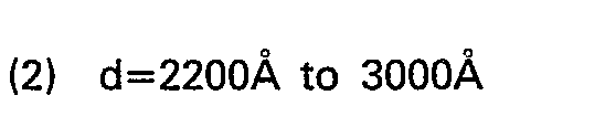
- By selecting the relation of thickness of the thin film and the wavelength, the polarity of R can be selected and the ΔR=[R2-R1 of more than 20% is obtainable.
- It is practically acceptable when utility factor A defined by

thin film 3 is from 60% to 95%. On the other hand, the utility factor A is also represented by
- When a thin film of the thickness of 2600A is used, AR is negative and the value is ΔR=x17(%), and the value is practical for recording on thin film.
- This second example is provided with a
reflection film 4 on the back face which is opposite to light incident face of thethin film 3. Such a reflection film is preferable especially for the case that the thickness of the thin film is very small and hence its transmission is over 50%. - For a
substrate 1, an acryl resin disk of the thickness of 1.0mm with very flat parallel faces is used, and athin film 3 mainly consisting of TeOx1 wherein 0<x1<2.0 is formed on thesubstrate 1 by a known vapor deposition method. Areflection film 4 of a vapor-deposited aluminum of 300A or more is disposed on theopposite face 72 to a light incident face 71 of thethin film 3. Further on the back face of the reflection film, a resin film for protection purpose may be provided. - Fig. 8 is a graph showing curves of changes of the reflections R1y and R2y of the
thin film 3 of this Example in relation to the change of film thickness d, for the non-recorded part and the recorded part, respectively. The curves R1 and R2 are the corresponding reflections of the previous Examples where no reflection film is provided, shown for a comparison. - In this Example, as the film thickness increases in the very thin region, the curve R1y for the reflection of the non-recorded part decreases, thereby nearing to the curve R1. It is to be noted that, in this Example, the curve R2, for the recorded part is lower than the curve R1y for such a wide region as up to 1500A of the thickness d. In other words, for the very wide region of d, the ΔR=R2-R1 is negative, and furthermore, the absolute value of AR is also so large as over 30%. Therefore, an efficient reproduction of information is possible for a wide range of the film thickness.
of the photo-
Claims (4)
Applications Claiming Priority (2)
| Application Number | Priority Date | Filing Date | Title |
|---|---|---|---|
| JP11846878A JPS5545166A (en) | 1978-09-25 | 1978-09-25 | Recording and reproducing method for optical information |
| JP118468/78 | 1978-09-25 |
Publications (2)
| Publication Number | Publication Date |
|---|---|
| EP0014227A1 EP0014227A1 (en) | 1980-08-20 |
| EP0014227B1 true EP0014227B1 (en) | 1986-06-04 |
Family
ID=14737407
Family Applications (1)
| Application Number | Title | Priority Date | Filing Date |
|---|---|---|---|
| EP79103628A Expired EP0014227B1 (en) | 1978-09-25 | 1979-09-24 | System and method of reproducing and erasing information |
Country Status (4)
| Country | Link |
|---|---|
| US (1) | US4330883A (en) |
| EP (1) | EP0014227B1 (en) |
| JP (1) | JPS5545166A (en) |
| DE (1) | DE2967601D1 (en) |
Families Citing this family (22)
| Publication number | Priority date | Publication date | Assignee | Title |
|---|---|---|---|---|
| US4544835A (en) * | 1983-12-29 | 1985-10-01 | Drexler Technology Corporation | Data system containing a high capacity optical contrast laser recordable wallet-size plastic card |
| US4542288A (en) * | 1981-02-27 | 1985-09-17 | Drexler Technology Corporation | Method for making a laser recordable wallet-size plastic card |
| US4425570A (en) | 1981-06-12 | 1984-01-10 | Rca Corporation | Reversible recording medium and information record |
| JPS58105442A (en) * | 1981-12-16 | 1983-06-23 | Ricoh Co Ltd | Optical recording and reproducing method |
| GB2121227A (en) * | 1982-05-11 | 1983-12-14 | Nigel Geoffrey Ley | Optical memory recording disc |
| JPS58224794A (en) * | 1982-06-25 | 1983-12-27 | Konishiroku Photo Ind Co Ltd | Optical information recording medium |
| US4809022A (en) * | 1983-06-27 | 1989-02-28 | Optical Disc Corporation | Direct read after write optical storage medium |
| DE3482147D1 (en) * | 1983-06-27 | 1990-06-07 | Optical Disc Corp | OPTICAL THIN FILM RECORDING MEDIUM WITH HIGH CONTRAST. |
| US4963901A (en) * | 1983-06-27 | 1990-10-16 | Optical Disc Corporation | Direct read after write optical storage medium and information storage system |
| JPS6174890A (en) * | 1984-09-21 | 1986-04-17 | Tdk Corp | Optical recording medium |
| US4908814A (en) * | 1986-02-07 | 1990-03-13 | Institut Problem Modelirovanija V Energetiki An Ukr. Ssr | Method of photothermal information recording reading and erasing |
| DE3752080T2 (en) * | 1986-12-17 | 1998-01-22 | Canon Kk | Device, method and device for optical modulation |
| US5090009A (en) * | 1988-07-30 | 1992-02-18 | Taiyo Yuden Co., Ltd. | Optical information recording medium |
| JP2719407B2 (en) * | 1989-07-06 | 1998-02-25 | 三洋電機株式会社 | Optical recording / reproducing method |
| DE69027103T2 (en) * | 1989-11-22 | 1996-10-24 | Sharp Kk | Optical recording medium and method for recording and reproducing information thereon |
| EP0458604B1 (en) * | 1990-05-22 | 1997-08-27 | Canon Kabushiki Kaisha | Method and apparatus for recording and reproducing information in cells using multiple interference |
| FR2676302B1 (en) * | 1991-05-07 | 1993-07-16 | Thomson Csf | METHOD FOR READING INFORMATION CONTAINED IN AN OPTICAL DISC. |
| JP3080739B2 (en) * | 1991-12-20 | 2000-08-28 | 日本電気株式会社 | Optical information recording medium and optical information recording / erasing / reproducing method |
| US6061749A (en) | 1997-04-30 | 2000-05-09 | Canon Kabushiki Kaisha | Transformation of a first dataword received from a FIFO into an input register and subsequent dataword from the FIFO into a normalized output dataword |
| JP3159374B2 (en) * | 1997-06-03 | 2001-04-23 | 日本電気株式会社 | Optical information recording medium |
| JP4164984B2 (en) | 2000-03-27 | 2008-10-15 | ソニー株式会社 | Optical recording medium |
| JP6645314B2 (en) | 2016-03-29 | 2020-02-14 | 株式会社デンソー | Spark plug for internal combustion engine and method of manufacturing the same |
Citations (2)
| Publication number | Priority date | Publication date | Assignee | Title |
|---|---|---|---|---|
| DE2536264A1 (en) * | 1974-09-09 | 1976-03-18 | Ibm | INFORMATION MEMORY WITH LASER BEAM INPUT |
| EP0004432A1 (en) * | 1978-03-20 | 1979-10-03 | Xerox Corporation | Optical storage system |
Family Cites Families (12)
| Publication number | Priority date | Publication date | Assignee | Title |
|---|---|---|---|---|
| NL278562A (en) * | 1961-05-19 | |||
| US3472575A (en) * | 1966-11-04 | 1969-10-14 | Ampex | Magnetic storage medium for enhancing magneto-optic readout |
| US3626386A (en) * | 1970-03-05 | 1971-12-07 | Energy Conversion Devices Inc | Information storage systems |
| US3665425A (en) * | 1970-03-09 | 1972-05-23 | Energy Conversion Devices Inc | Information storage systems utilizing amorphous thin films |
| US3747117A (en) * | 1971-03-31 | 1973-07-17 | Teletype Corp | Laser writing |
| US3971874A (en) * | 1973-08-29 | 1976-07-27 | Matsushita Electric Industrial Co., Ltd. | Optical information storage material and method of making it |
| US4069487A (en) * | 1974-12-26 | 1978-01-17 | Canon Kabushiki Kaisha | Recording member and process for recording |
| US4125860A (en) * | 1975-06-16 | 1978-11-14 | Nippon Telegraph And Telephone Public Corporation | Reproducer for an eraseable videodisc |
| US4097895A (en) * | 1976-03-19 | 1978-06-27 | Rca Corporation | Multilayer optical record |
| FR2355337A1 (en) * | 1976-06-18 | 1978-01-13 | Thomson Brandt | Optical read-write system for disc memories - has disc sandwiched between covers to prevent errors due to dust particles or surface scratches (NL 20.12.77) |
| US4161752A (en) * | 1977-06-28 | 1979-07-17 | International Business Machines Corporation | High density video disk having two pit depths |
| US4233626A (en) * | 1979-01-11 | 1980-11-11 | Rca Corporation | Playback information record using phase cancellation for reading |
-
1978
- 1978-09-25 JP JP11846878A patent/JPS5545166A/en active Granted
-
1979
- 1979-09-18 US US06/076,725 patent/US4330883A/en not_active Expired - Lifetime
- 1979-09-24 EP EP79103628A patent/EP0014227B1/en not_active Expired
- 1979-09-24 DE DE7979103628T patent/DE2967601D1/en not_active Expired
Patent Citations (2)
| Publication number | Priority date | Publication date | Assignee | Title |
|---|---|---|---|---|
| DE2536264A1 (en) * | 1974-09-09 | 1976-03-18 | Ibm | INFORMATION MEMORY WITH LASER BEAM INPUT |
| EP0004432A1 (en) * | 1978-03-20 | 1979-10-03 | Xerox Corporation | Optical storage system |
Non-Patent Citations (2)
| Title |
|---|
| IBM Technical Disclosure Bulletin, Vol. 113 p. 3001-3002 * |
| IEEE Spectrum Vol. 15, No. 8 Aug. 1978 p. 20-27 * |
Also Published As
| Publication number | Publication date |
|---|---|
| JPS6240767B2 (en) | 1987-08-31 |
| JPS5545166A (en) | 1980-03-29 |
| EP0014227A1 (en) | 1980-08-20 |
| US4330883A (en) | 1982-05-18 |
| DE2967601D1 (en) | 1986-07-10 |
Similar Documents
| Publication | Publication Date | Title |
|---|---|---|
| US4330883A (en) | System and method of optical information storage in a recording disc | |
| CA1220552A (en) | Information recording medium | |
| US6469977B2 (en) | Optical information recording medium, method for producing the same, and method and apparatus for recording/reproducing information thereon | |
| US5249175A (en) | Optical information recording medium and information recording and reproducing method therefor | |
| US5631895A (en) | Optical information recording medium | |
| US6660356B1 (en) | Optical information recording medium, method for producing the same, and method and apparatus for recording/reproducing information thereon | |
| US5811217A (en) | Optical information recording medium and optical information recording/reproducing method | |
| EP0548828B1 (en) | An optical data recording media and a method for recording, erasing and reproducing data on the same | |
| US6628603B1 (en) | Dual layer optical storage medium having partially reflecting layer comprising antimony sulfide | |
| CN1211789A (en) | Optical information recording medium and its recording and reproducing method | |
| JPS59113534A (en) | Optical recording medium | |
| EP0360466B1 (en) | Optical information recording medium and information recording and reproducing method therefor | |
| JP2661293B2 (en) | Optical information recording medium | |
| US5527661A (en) | Optical information recording medium | |
| CA1235901A (en) | High contrast thin film optical recording medium | |
| JP3287860B2 (en) | Optical information recording method and recording medium | |
| JPS62245545A (en) | Information recording medium | |
| JPH0273537A (en) | Optical information recording medium | |
| JP3156418B2 (en) | Optical information recording medium and optical information recording / reproducing method | |
| JP3206165B2 (en) | Optical information recording medium | |
| US5812182A (en) | Optical information recording medium for recording erasing and play back of compact disc signals | |
| JPH07105064B2 (en) | Optical information recording medium | |
| JPH07134838A (en) | Optical information recording medium and recording method | |
| JPH0917028A (en) | Optical information recording medium and information reproducing method thereof | |
| JP2551930B2 (en) | Optical recording medium |
Legal Events
| Date | Code | Title | Description |
|---|---|---|---|
| PUAI | Public reference made under article 153(3) epc to a published international application that has entered the european phase |
Free format text: ORIGINAL CODE: 0009012 |
|
| AK | Designated contracting states |
Designated state(s): DE FR GB NL |
|
| 17P | Request for examination filed | ||
| GRAA | (expected) grant |
Free format text: ORIGINAL CODE: 0009210 |
|
| AK | Designated contracting states |
Kind code of ref document: B1 Designated state(s): DE FR GB NL |
|
| REF | Corresponds to: |
Ref document number: 2967601 Country of ref document: DE Date of ref document: 19860710 |
|
| ET | Fr: translation filed | ||
| PLBE | No opposition filed within time limit |
Free format text: ORIGINAL CODE: 0009261 |
|
| STAA | Information on the status of an ep patent application or granted ep patent |
Free format text: STATUS: NO OPPOSITION FILED WITHIN TIME LIMIT |
|
| 26N | No opposition filed | ||
| PGFP | Annual fee paid to national office [announced via postgrant information from national office to epo] |
Ref country code: FR Payment date: 19980909 Year of fee payment: 20 |
|
| PGFP | Annual fee paid to national office [announced via postgrant information from national office to epo] |
Ref country code: NL Payment date: 19980929 Year of fee payment: 20 |
|
| PGFP | Annual fee paid to national office [announced via postgrant information from national office to epo] |
Ref country code: GB Payment date: 19981001 Year of fee payment: 20 |
|
| PGFP | Annual fee paid to national office [announced via postgrant information from national office to epo] |
Ref country code: DE Payment date: 19981005 Year of fee payment: 20 |
|
| PG25 | Lapsed in a contracting state [announced via postgrant information from national office to epo] |
Ref country code: GB Free format text: LAPSE BECAUSE OF NON-PAYMENT OF DUE FEES Effective date: 19990923 |
|
| PG25 | Lapsed in a contracting state [announced via postgrant information from national office to epo] |
Ref country code: NL Free format text: LAPSE BECAUSE OF EXPIRATION OF PROTECTION Effective date: 19990924 |
|
| REG | Reference to a national code |
Ref country code: GB Ref legal event code: PE20 Effective date: 19990923 |
|
| NLV7 | Nl: ceased due to reaching the maximum lifetime of a patent |
Effective date: 19991024 |