EP0014122A1 - Hydromechanical skid steering device - Google Patents
Hydromechanical skid steering device Download PDFInfo
- Publication number
- EP0014122A1 EP0014122A1 EP80400047A EP80400047A EP0014122A1 EP 0014122 A1 EP0014122 A1 EP 0014122A1 EP 80400047 A EP80400047 A EP 80400047A EP 80400047 A EP80400047 A EP 80400047A EP 0014122 A1 EP0014122 A1 EP 0014122A1
- Authority
- EP
- European Patent Office
- Prior art keywords
- shaft
- hydromechanical
- planetary gear
- steering device
- wheel
- Prior art date
- Legal status (The legal status is an assumption and is not a legal conclusion. Google has not performed a legal analysis and makes no representation as to the accuracy of the status listed.)
- Granted
Links
- 230000005540 biological transmission Effects 0.000 claims abstract description 30
- 230000002706 hydrostatic effect Effects 0.000 claims abstract description 19
- 230000009467 reduction Effects 0.000 claims abstract description 3
- 238000006073 displacement reaction Methods 0.000 claims description 30
- 230000008878 coupling Effects 0.000 claims description 5
- 238000010168 coupling process Methods 0.000 claims description 5
- 238000005859 coupling reaction Methods 0.000 claims description 5
- 230000003100 immobilizing effect Effects 0.000 claims description 2
- 230000007704 transition Effects 0.000 claims description 2
- 230000036461 convulsion Effects 0.000 abstract 1
- 230000007935 neutral effect Effects 0.000 description 4
- 230000008901 benefit Effects 0.000 description 3
- 239000012530 fluid Substances 0.000 description 3
- 230000000694 effects Effects 0.000 description 2
- 230000001970 hydrokinetic effect Effects 0.000 description 2
- 230000008859 change Effects 0.000 description 1
- 238000006243 chemical reaction Methods 0.000 description 1
- 238000010276 construction Methods 0.000 description 1
- 230000003247 decreasing effect Effects 0.000 description 1
- 238000013021 overheating Methods 0.000 description 1
- 230000011514 reflex Effects 0.000 description 1
- 230000008929 regeneration Effects 0.000 description 1
- 238000011069 regeneration method Methods 0.000 description 1
- 230000001960 triggered effect Effects 0.000 description 1
Images


Classifications
-
- B—PERFORMING OPERATIONS; TRANSPORTING
- B62—LAND VEHICLES FOR TRAVELLING OTHERWISE THAN ON RAILS
- B62D—MOTOR VEHICLES; TRAILERS
- B62D11/00—Steering non-deflectable wheels; Steering endless tracks or the like
- B62D11/02—Steering non-deflectable wheels; Steering endless tracks or the like by differentially driving ground-engaging elements on opposite vehicle sides
- B62D11/06—Steering non-deflectable wheels; Steering endless tracks or the like by differentially driving ground-engaging elements on opposite vehicle sides by means of a single main power source
- B62D11/10—Steering non-deflectable wheels; Steering endless tracks or the like by differentially driving ground-engaging elements on opposite vehicle sides by means of a single main power source using gearings with differential power outputs on opposite sides, e.g. twin-differential or epicyclic gears
- B62D11/14—Steering non-deflectable wheels; Steering endless tracks or the like by differentially driving ground-engaging elements on opposite vehicle sides by means of a single main power source using gearings with differential power outputs on opposite sides, e.g. twin-differential or epicyclic gears differential power outputs being effected by additional power supply to one side, e.g. power originating from secondary power source
- B62D11/18—Steering non-deflectable wheels; Steering endless tracks or the like by differentially driving ground-engaging elements on opposite vehicle sides by means of a single main power source using gearings with differential power outputs on opposite sides, e.g. twin-differential or epicyclic gears differential power outputs being effected by additional power supply to one side, e.g. power originating from secondary power source the additional power supply being supplied hydraulically
Definitions
- the present invention relates to the technical field of steering devices for vehicles and more particularly for vehicles with tracks or with non-steerable wheels, vehicles such as public works vehicles or battle tanks.
- An important problem posed by vehicles with tracks or with non-steerable wheels is to obtain a continuous variation in the turning radii when cornering.
- Another solution consists in adding to the hydrostatic direction hydrokinetic or purely mechanical devices which are used only in the most difficult cases of use.
- this provision requires the use of coupling devices such as clutches or dog clutch to allow the temporary grouping of these various elements when it is necessary to use all of the available power, for example in the case short cornering radii for which the power required for cornering is significant.
- the aim of the device according to the invention is to provide a continuous solution to the problem of variation of the turning radii of the vehicle, while avoiding the aforementioned drawbacks.
- the subject of the invention is therefore a hydromechanical steering device for vehicles with tracks or with non-steerable wheels allowing, under load, the continuous and smooth transition from hydraulic operation to hydro-mechanical operation, driven by a motor.
- the momentary immobilization device can be constituted by two free wheels mounted in opposition to the locking direction cooperating with immobilization means.
- the immobilization means then consist of two brakes with hydraulic, electromagnetic, or mechanical control.
- the hydrostatic transmission of the hydromechanical device may comprise at least one hydraulic circuit comprising one or more pumps and one or more hydraulic motors, the displacement of each of these elements being able to be fixed or variable, each pump being driven by the first shaft transmission and the output shaft of each motor driving the central wheel of the first planetary gear via a gear train.
- variable displacement element can be controlled by the vehicle's steering wheel, either directly or by means of any intermediate mechanical, electrical or hydraulic device.
- the clutch device is composed of an intermediate shaft carrying a pinion connecting it to the first transmission shaft and two sets of discs, and by two clutch receivers, these two clutches being able to be controlled independently. one from the other, the two shafts coupled by the clutch device having substantially the same speed of rotation, at the time of coupling.
- Each clutch receiver is connected to the shaft carrying the central wheel of the second planetary gear, the first receiver being connected to it by an even number and the second by an odd number of intermediate gears.
- the freewheels mounted in opposition are composed of two internal rings arranged on the shaft carrying the planet carrier arms of the first planetary gear train and the crown of the second planetary gear train and of two external rings cooperating with the means immobilization.
- the hydrostatic transmission is split, which implies a different arrangement of the members constituting the steering device.
- the hydrostatic transmission comprises two identical hydraulic circuits.
- Each of the pumps is driven by the first transmission shaft which further carries two toothed wheels and each motor drives each of the ends of a second intermediate shaft which drives the central wheel of the first planetary gear via a gear train .
- the second planetary gear train comprises a double satellite connected to two central wheels, each of these central wheels driving a shaft which carries at each of these ends a clutch receiver.
- the set of discs of each of these clutches is carried by a hollow half-shaft driven in rotation by each toothed wheel of the first transmission shaft, the first and the second half-shaft being driven respectively by means of an even number and of an odd number of intermediate gears.
- the crown of the second planetary gear train cooperates by means of a gear train with the momentary immobilization device, the latter being carried by a hollow shaft concentric with the second intermediate shaft.
- the shaft carrying the crown of the first planetary gear train drives in opposite directions the central wheels of two output epicycles, the crowns of which cooperate with the gearbox and the planet carrier arms of which drive the wheels driving.
- the two devices defined above have their first transmission shaft connected to the heat engine by an inverter and are characterized in that the pump of each hydrostatic transmission is rotated downstream of the inverter so that the vehicle is turned in the direction of rotation of the steering wheel, in forward, and in the opposite direction in reverse, which allows to keep the same trajectory.
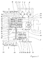
- FIG 1 schematically shows the first embodiment briefly described above and Figure 2 the second embodiment.
- Figure 3 shows on the ordinate a possible example of the variations in the displacement of the hydraulic transmission pump as well as the braking and clutch application ranges of the device as a function of the position (on the abscissa) of the steering wheel from its position median to its stop position.
- a rotation to the right of the steering wheel will correspond to the positive abscissa part of the curves while a rotation to the left of the steering wheel will correspond to their negative abscissa part.
- FIG. 1 therefore shows a hydromechanical steering device used on a vehicle comprising a heat engine 1 which can be associated with a torque converter or a clutch and transmitting its power to a first drive shaft 2 via a reverse gear 4, comprising a double bevel gear 3 and 3a.
- a heat engine 1 which can be associated with a torque converter or a clutch and transmitting its power to a first drive shaft 2 via a reverse gear 4, comprising a double bevel gear 3 and 3a.
- the first transmission shaft drives at one of its ends the rotation of the variable displacement pump 6 of a hydraulic transmission 5.
- This also consists of a hydraulic circuit 7 which allows the pump 6 to flow into a motor hydraulic 8.
- the latter drives the central wheel 13 of the first planetary gear train, by means of a gear train here represented by the gears 9 and 10.
- the latter train is disposed at one end of a hollow shaft 11 mounted on the 'output shaft 12 of the steering device.
- the hollow shaft carries at its second end the aforementioned central wheel 13.
- the epicyclic double train 14 is arranged so that the arm 15, which carries the satellites 16 of the first train, is connected to the crown 17 of the second train.
- the arm 18 carrying the satellites 19 of the second train is connected to the crown 20 of the first train.
- the speed of rotation of the planet carrier shaft of each planetary gear train is equal to that of the crown of the other train.
- the shaft 21 carrying the satellites 16 of the first train and the crown 17 of the second train is a hollow shaft arranged around the shaft 11 and, of course, having the same axis of rotation as the tree 12.
- the double planetary gear 14 cooperates with the momentary immobilization device 22 by means of the aforementioned shaft 21. Indeed the latter carries the internal rings of two free wheels 23 and 24 mounted in opposition to the locking direction and belonging to the immobilizing device 22. The latter is completed by two brakes cooperating with the outer rings of the two freewheels 23 and 24.
- the device 22 thus makes it possible to make the position of the crown 17 of the second planetary gear train fixed, and the arm 15 of the first train or make it possible according to the chosen operation, the rotation of these in one direction or the other.
- the locking and unlocking control of each of the brakes 25 and 26 is fixed by the position of the vehicle steering wheel.
- the double planetary gear 14 cooperates with the first transmission shaft 2 by means of the clutch device 27.
- the clutch device 27 comprises, as can be seen in FIG. 1, two clutches 31 and 32, the disks of which are mounted on an intermediate shaft 28 coupled by a gear train 29, 30 to the first transmission shaft 2.
- the two clutch receivers 31 and 32 are linked to the central wheel 33 of the second planetary gear with a hollow shaft 34 concentric with the shaft 12 and an even and odd number of gears respectively, which makes it possible to drive in one way or the other the rotation of the central wheel of the second train.
- the two clutches 31 and 32 are controlled by any appropriate means by the position of the steering control wheel.
- each of the two clutches can only be tightened when the two parts then coupled (respectively one of the receivers of the clutches 31 and 32 of the shaft 28) have approximately equal speed.
- the pump 6 does not rotate and the two brakes 25 and 26 are applied if the steering wheel is in the middle position ("straight line” position). Due to this position of the steering wheel, the two clutches 31 and 32 are free.
- the vehicle is then in neutral.
- the drive shaft 2 rotates in a determined direction and rotates in the same direction h pump 6.
- the flywheel is always in the middle position, the pump is at zero flow and the hydraulic motor 8 can't turn.
- the vehicle can then be moved in a straight line exclusively and entirely mechanically.
- the displacement of the pump 6 and the direction of circulation of the fluid in the circuit 7 are controlled so that by passing the flywheel from its middle position to its abutment position, the displacement of the pump 6 passes from the zero value to a maximum to decrease then until the zero value then increase again with an invention of the direction of circulation of fluid in the circuit 7 as it appears on figure 3.
- the curve located at the bottom of the figure shows a possible variation mode of the displacement of the pump.
- the negative displacement will represent the variation of the displacement when it is accompanied by the change of direction of fluid circulation in the circuit 7.
- the curve is shown here by way of example, the important points being those of zero and maximum displacement, the variation between these points being a function of the control device chosen in practice.
- the upper part of the curve shows in solid lines with reference to the brakes 25 and 26 and the clutches 31 and 32 the tightening ranges of these various elements as a function of variations in the displacement of the pump and the rotational movements of the flywheel .
- the hydraulic motor 8 starts to rotate as does the central wheel 13 of the first planetary gear.
- the planet carrier arm 15 being immobilized by one of the brakes 25 or 26, the rotation of the central wheel 13 causes that of the planet carrier arm 18 of the second planetary gear train and therefore that of the steering shaft 12.
- the flywheel corresponds the maximum displacement of the pump-6.
- the kinematics of the device is such that at this position also corresponds an equalization of the speeds of the shaft 28 and that of the two clutches which rotates in the same direction as the shaft 28 with however a slight advance with respect to the latter.
- the central wheel 33 of the second planetary gear train then rotates in the direction of the shaft 12 while the central wheel of the first planetary gear train rotates in the opposite direction imposed on it by the direction of rotation of the motor 8, which serves as a support mobile and becomes a receiver.
- the speed of rotation of the latter is fixed by the displacement of the pump 6.
- the motor 8 and the central wheel 13 tend to come to a stop, which accelerates the shaft 12 and therefore the pivoting speed of the vehicle.
- the engine speed 8 increases with the displacement of the pump 6, and the central wheel 13 of the first train accelerates its rotation, in the same direction as the shaft 12, and again the pivoting speed increases.
- the pivoting is stopped by returning the steering wheel to its neutral position regardless of its previous position.
- the turning radius will depend only on the momentary displacement of the pump, the direction of rotation of the motor 8 of the application of the various brakes and clutches .
- the device according to the invention can be arranged according to a second embodiment, the particulars of which will be specified below, in relation to FIG. 2.
- the second embodiment of the invention will include two symmetrical hydraulic transmissions 5 and 5a.
- variable displacement hydraulic pump (6 and 6a) is disposed on each end of the first transmission shaft, each delivering a motor with a fixed displacement (respectively 8 and 8a).
- the two motors 8 and 8a are then connected together by a second intermediate shaft 46 which transmits its hydraulic power to the central wheel 13 of the first planetary gear via a gear train 9, 10 and the shaft hollow 11 carrying the central wheel.
- the mechanical power coming from the heat engine and passing through the clutches 31 and 32, is transmitted to the double planetary gear from the shaft 2 by two gear trains, one containing an even number (respectively 39.40) and the another an odd number (respectively 41, 42 and 43) of gears.
- the wheels 40 and 43 are carried by two hollow half-shafts 44 and 45 concentric with the shaft 12 and supporting the discs of the clutches 31 and 32 whose receivers are also carried by two other hollow half-shafts concentric with the shaft 12 and supporting central wheels 33a and 33b.
- the second planetary gear train is double in the sense that it includes a double central wheel (33a and 33b), double satellites (19 a and 19 b) carried by the planet carrier arm 18.
- the duplication of the second train allows then a better distribution of the forces on the various elements constituting it.
- the double planetary gear 14 cooperates by means of a gear train with the device 22 for momentary immobilization which is arranged for reasons of convenience on a hollow shaft carried by the second intermediate shaft 46.
- This arrangement interposing a gear between the double train 14 and the device 22 makes it possible to adapt to the capacity of the brakes 25 and 26 and of the free wheels 23 and 24 making up the latter, the large torque transmitted by the planet carrier arm 15.
- the mechanical elements are coupled under load, smoothly, automatically by the presence of the free wheels and without slippage, which avoids wasted power and therefore improves efficiency compared with prior art.
Abstract
Description
La présente invention concerne le domaine technique des dispositifs de direction pour véhicules et plus particulièrement pour véhicules à chenilles ou à roues non orientables, véhicules tels que des engins de travaux publics ou des chars de combat.The present invention relates to the technical field of steering devices for vehicles and more particularly for vehicles with tracks or with non-steerable wheels, vehicles such as public works vehicles or battle tanks.
Un problème important posé par les véhicules à chenilles ou à roues non orientables est d'obtenir en virage une variation continue des rayons de braquage.An important problem posed by vehicles with tracks or with non-steerable wheels is to obtain a continuous variation in the turning radii when cornering.
Pour résoudre ce problème, des solutions ont été proposées. Ainsi on a utilisé des dispositifs de direction hydrostatiques qui lui apportent une solution satisfaisante pour des véhicules ne nécessitant pas une forte puissance de direction.To solve this problem, solutions have been proposed. Thus, hydrostatic steering devices have been used which provide it with a satisfactory solution for vehicles which do not require high steering power.
Pour des puissances de virages élevées, on peut alors envisager d'augmenter le nombre des composants hydrostatiques utilisés. Cette solution entièrement hydrostatique, techniquement possible, grève cependant le véhicule d'un encombrement et d'un poids supplémentaires excessifs et incompatibles avec les exigences globales de masse et d'encombrement de celui-ci.For high cornering powers, it is then possible to envisage increasing the number of hydrostatic components used. This entirely hydrostatic solution, technically possible, puts a heavy burden on the vehicle and excessive excess weight, which is incompatible with the overall requirements for mass and overall dimensions.
Une autre solution consiste à ajouter à la direction hydrostatique des dispositifs hydrocinétiques ou purement mécaniques que l'on ne met en oeuvre que dans les cas d'utilisation les plus difficiles.Another solution consists in adding to the hydrostatic direction hydrokinetic or purely mechanical devices which are used only in the most difficult cases of use.
Cette solution permet de limiter la fraction de puissance qui transite par les éléments hydrauliques, la puissance supplémentaire nécessaire au virage étant apportée par les éléments mécaniques ou hydrocinétiques.This solution makes it possible to limit the fraction of power which passes through the hydraulic elements, the additional power necessary for the turn being provided by the mechanical or hydrokinetic elements.
Dans certains cas, cette disposition impose l'emploi de dispositifs de couplage tels que des embrayages ou des crabotages pour permettre le groupement temporaire de ces divers éléments lorsqu'il est nécessaire d'utiliser la totalité de la puissance disponible, par exemple dans le cas de rayons courts de virage pour lesquels la puissance nécessaire au virage est importante.In some cases, this provision requires the use of coupling devices such as clutches or dog clutch to allow the temporary grouping of these various elements when it is necessary to use all of the available power, for example in the case short cornering radii for which the power required for cornering is significant.
Au moment du passage d'un mode de fonctionnement à un autre, on peut alors perdre le bénéfice de la variation continue du rayon, qu'apportait l'hydrostatique.When switching from one operating mode to another, we can then lose the benefit of the continuous variation of the radius, brought by the hydrostatic.
Les dispositifs autres que les crabotages utilisent pour le couplage des divers éléments, des dispositifs à embrayage ou à frein pour réaliser le couplage "dans la foulée". Une telle solution est utilisée dans le dispositif décrit dans la demande de brevet française N° 74.30524 et publiée sous le N° 2 284 504. .../...Devices other than dog clutching use for coupling the various elements, clutch or brake devices for coupling "in stride". Such a solution is used in the device described in French patent application No. 74.30524 and published under No. 2 284 504. ... / ...
Ces dispositifs à embrayages sont rendus nécessaires par le fait que les divers éléments à coupler ont des vitesses de rotation différentes. On se rend compte immédiatement que ces dispositifs entraînent soit des glissements qui ont pour conséquence des risques d'échauffement important et d'usure, soit des à-coups.These clutch devices are made necessary by the fact that the various elements to be coupled have different rotational speeds. We immediately realize that these devices cause either slippage which results in significant risks of overheating and wear, or jolts.
Le dispositif selon l'invention a pour but de fournir une solution continue au problème de variation des rayons de braquage du véhicule, tout en évitant les inconvénients précités.The aim of the device according to the invention is to provide a continuous solution to the problem of variation of the turning radii of the vehicle, while avoiding the aforementioned drawbacks.
L'invention a donc pour objet un dispositif de direction hydromécanique pour véhicules à chenilles ou à roues non orientables permettant, en charge, le passage continu et sans à-coups d'un fonctionnement hydraulique à un fonctionnement hydro-mécanique, entraîné par un moteur thermique relié à un premier arbre de transmission commandant le sens de rotation d'une boîte de vitesses et le fonctionnement d'une transmission hydrostatique, dispositif caractérisé en ce qu'il comprend un double train réducteur composé de deux trains épicycloïdaux réunis de sorte que le bras porte-satellites de chacun d'eux soit relié à la couronne de l'autre, la roue centrale du premier train épicycloïdal coopérant au moyen d'un dispositif à embrayages avec le premier arbre de commande du sens de rotation de la boîte de vitesses, et en ce que l'arbre portant les bras porte-satellites du premier train épicycloïdal et la couronne du second train épicycloïdal est muni d'une dispositif d'immobilisation momentanée.The subject of the invention is therefore a hydromechanical steering device for vehicles with tracks or with non-steerable wheels allowing, under load, the continuous and smooth transition from hydraulic operation to hydro-mechanical operation, driven by a motor. thermal connected to a first transmission shaft controlling the direction of rotation of a gearbox and the operation of a hydrostatic transmission, device characterized in that it comprises a double reduction gear consisting of two epicyclic trains joined together so that the planet carrier arm of each of them is connected to the crown of the other, the central wheel of the first planetary gear train cooperating by means of a clutch device with the first shaft controlling the direction of rotation of the gearbox , and in that the shaft carrying the planet carrier arms of the first planetary gear and the crown of the second planetary gear is provided with a momentary immobilization device.
Selon une autre caractéristique, le dispositif d'immobilisation momentanée peut être constitué par deux roues libres montées en opposition de sens de blocage coopérant avec des moyens d'immobilisation.According to another characteristic, the momentary immobilization device can be constituted by two free wheels mounted in opposition to the locking direction cooperating with immobilization means.
Les moyens d'immobilisation sont alors constitués par deux freins à commande hydraulique Jélectromagnétique, ou mécanique.The immobilization means then consist of two brakes with hydraulic, electromagnetic, or mechanical control.
La transmission hydrostatique du dispositif hydromécanique selon l'invention peut comporter au moins un circuit hydraulique comprenant une ou plusieurs pompes et un ou plusieurs moteurs hydrauliques, la cylindrée de chacun de ces éléments pouvant être fixe ou variable, chaque pompe étant entraînée par le premier arbre de transmission et l'arbre de sortie de chaque moteur entraînant la roue centrale du premier train épicycloïdal par l'intermédiaire d'un train à engrenages.The hydrostatic transmission of the hydromechanical device according to the invention may comprise at least one hydraulic circuit comprising one or more pumps and one or more hydraulic motors, the displacement of each of these elements being able to be fixed or variable, each pump being driven by the first shaft transmission and the output shaft of each motor driving the central wheel of the first planetary gear via a gear train.
La variation de cylindrée de chaque élément àcylindrée variable pourra être commandée par le volant de direction du véhicule, soit directement, soit au moyen de tout dispositif mécanique, électrique ou hydraulique intermédiaire.The variation in displacement of each variable displacement element can be controlled by the vehicle's steering wheel, either directly or by means of any intermediate mechanical, electrical or hydraulic device.
Selon un mode de réalisation conforme aux définitions précitées, le dispositif à embrayages est composé par un arbre intermédiaire portant un pignon le reliant au premier arbre de transmission et deux ensembles de disques, et par deux récepteurs d'embrayages ces deux embrayages pouvant être commandés indépendamment l'un de l'autre, les deux arbres accouplés par le dispositif à embrayages ayant sensiblement la même vitesse de rotation, au moment de l'accouplement. Chaque récepteur d'embrayage est relié à l'arbre portant la roue centrale du deuxième train épicycloïdal, le premier récepteur y étant relié par un nombre pair et le second par un nombre impair d'engrenages intermédiaires.According to an embodiment in accordance with the above definitions, the clutch device is composed of an intermediate shaft carrying a pinion connecting it to the first transmission shaft and two sets of discs, and by two clutch receivers, these two clutches being able to be controlled independently. one from the other, the two shafts coupled by the clutch device having substantially the same speed of rotation, at the time of coupling. Each clutch receiver is connected to the shaft carrying the central wheel of the second planetary gear, the first receiver being connected to it by an even number and the second by an odd number of intermediate gears.
Selon ce même mode de réalisation, les roues libres montées en opposition sont composées de deux bagues internes disposées sur l'arbre portant les bras porte-satellites du premier train épicycloidal et la couronne du second train épicycloïdal et de deux bagues externes coopérant avec les moyens d'immobilisation.According to this same embodiment, the freewheels mounted in opposition are composed of two internal rings arranged on the shaft carrying the planet carrier arms of the first planetary gear train and the crown of the second planetary gear train and of two external rings cooperating with the means immobilization.
Un autre mode de réalisation est plus directement applicable aux véhicules nécessitant une forte puissance de direction. Selon ce mode de réalisation la transmission hydrostatique est dédoublée, ce qui implique un arrangement différent des organes constituant le dispositif de direction. Ainsi la transmission hydrostatique comporte deux circuits hydrauliques identiques. Chacune des pompes est entraînée par le premier arbre de transmission qui porte de plus deux roues dentées et chaque moteur entraîne chacune des extrémités d'un second arbre intermédiaire qui conduit la roue centrale du premier train épicycloïdal par l'intermédiaire d'un train à engrenages.Another embodiment is more directly applicable to vehicles requiring high steering power. According to this embodiment, the hydrostatic transmission is split, which implies a different arrangement of the members constituting the steering device. Thus the hydrostatic transmission comprises two identical hydraulic circuits. Each of the pumps is driven by the first transmission shaft which further carries two toothed wheels and each motor drives each of the ends of a second intermediate shaft which drives the central wheel of the first planetary gear via a gear train .
De plus, le deuxième train épicycloïdal comporte un satellite double relié à deux roues centrales, chacune de ces roues centrales entraînant un arbre qui porte à chacune de ces extrémités un récepteur d'embrayage. L'ensemble des disques de chacun de ces embrayages est porté par un demi-arbre creux entraîné en rotation par chaque roue dentée du premier arbre de transmission, le premier et le second demi-arbre étant entraînés respectivement au moyen d'un nombre pair et d'un nombre impair d'engrenages intermédiaires.In addition, the second planetary gear train comprises a double satellite connected to two central wheels, each of these central wheels driving a shaft which carries at each of these ends a clutch receiver. The set of discs of each of these clutches is carried by a hollow half-shaft driven in rotation by each toothed wheel of the first transmission shaft, the first and the second half-shaft being driven respectively by means of an even number and of an odd number of intermediate gears.
En outre, la couronne du second train épicycloïdal coopère au moyen d'un train d'engrenages avec le dispositif d'immobilisation momentanée, ce dernier étant porté par un arbre creux concentrique avec le second arbre intermédiaire.In addition, the crown of the second planetary gear train cooperates by means of a gear train with the momentary immobilization device, the latter being carried by a hollow shaft concentric with the second intermediate shaft.
Selon ces deux modes de réalisation, l'arbre portant la couronne du premier train épicycloïdal entraîne dans des sens opposés les roues centrales de deux épicycles de sortie, dont les couronnes coopèrent avec la boîte de vitesses et dont les bras porte-satellites entraînent les roues motrices.According to these two embodiments, the shaft carrying the crown of the first planetary gear train drives in opposite directions the central wheels of two output epicycles, the crowns of which cooperate with the gearbox and the planet carrier arms of which drive the wheels driving.
Les deux dispositifs définis précédemment ont leur premier arbre de transmission relié au moteur thermique par un inverseur et sont caractérisés en ce que la pompe de chaque transmission hydrostatique est entraînée en rotation en aval de l'inverseur de sorte que le virage du véhicule soit effectué dans le sens de rotation du volant, en marche avant, et dans le sens opposé en marche arrière, ce qui permet de conserver la même trajectoire.The two devices defined above have their first transmission shaft connected to the heat engine by an inverter and are characterized in that the pump of each hydrostatic transmission is rotated downstream of the inverter so that the vehicle is turned in the direction of rotation of the steering wheel, in forward, and in the opposite direction in reverse, which allows to keep the same trajectory.
L'invention sera décrite plus en détail en regard des dessins annexés à titre d'exemples nullement limitatifs de deux cas particuliers de réalisation du dispositif de direction hydromécanique selon l'invention et de leur mode de fonctionnement.The invention will be described in more detail with reference to the accompanying drawings by way of non-limiting examples of two particular cases of embodiment of the hydromechanical steering device according to the invention and of their mode of operation.
La figure 1 représente schématiquement le premier mode de réalisation brièvement décrit ci-dessus et la figure 2 le second mode de réalisation.Figure 1 schematically shows the first embodiment briefly described above and Figure 2 the second embodiment.
La figure 3 représente en ordonnée un exemple possible des variations de la cylindrée de la pompe de la transmission hydraulique ainsi que les plages de serrage des freins et des embrayages du dispositif en fonction de la position (en abscisse) du volant de direction de sa position médiane à sa position en butée. Une rotation à droite du volant correspondra à la partie d'abscisse positive des courbes alors qu'une rotation à gauche du volant correspondra à leur partie d'abscisse négative.Figure 3 shows on the ordinate a possible example of the variations in the displacement of the hydraulic transmission pump as well as the braking and clutch application ranges of the device as a function of the position (on the abscissa) of the steering wheel from its position median to its stop position. A rotation to the right of the steering wheel will correspond to the positive abscissa part of the curves while a rotation to the left of the steering wheel will correspond to their negative abscissa part.
Sur la figure 1 on voit donc un dispositif de direction hydromécanique utilisé sur un véhicule comprenant un moteur thermique 1 pouvant être associé à un convertisseur de couple ou un embrayage et transmettant sa puissance à un premier arbre de transmission 2 par l'intermédiaire d'un inverseur de marche 4, comportant un double couple conique 3 et 3a.FIG. 1 therefore shows a hydromechanical steering device used on a vehicle comprising a
Cet inverseur permet le passage du véhicule en marche avant ou en marche arrière suivant que le premier ou le second . couple conique 3 ou 3a est en prise sur le premier arbre de transmission 2.This reverser allows the vehicle to go forward or reverse depending on whether the first or the second.
Le premier arbre de transmission entraîne à une de ses extrémités la rotation de la pompe à cylindrée variable 6 d'une transmission hydraulique 5. Celle-ci est formée également d'un circuit hydraulique 7 qui permet à la pompe 6 de débiter dans un moteur hydraulique 8. Ce dernier entraîne la roue centrale 13 du premier train épicycloîdal, au moyen d'un train d'engrenages ici représenté par les engrenages 9 et 10. Ce dernier train est disposé à une extrémité d'un arbre creux 11 monté sur l'arbre de sortie 12 du dispositif de direction. L'arbre creux porte à sa deuxième extrémité la roue centrale 13 précitée.The first transmission shaft drives at one of its ends the rotation of the
Le double train 14 épicycloïdal est disposé de telle sorte que le bras 15, qui porte les satellites 16 du premier train, soit relié à la couronne 17 du second train.The epicyclic
De même le bras 18 portant les satellites 19 du second train est relié à la couronne 20 du premier train. De cette façon, la vitesse de rotation de l'arbre porte-satellites de chaque train épicycloïdal est égale à celle de la couronne de l'autre train.Similarly, the
Sur la figure 1 on voit que l'arbre 21 porteur des satellites 16 du premier train et de la couronne 17 du second train est un arbre creux disposé autour de l'arbre 11 et, bien sûr, ayant le même axe de rotation que l'arbre 12.In Figure 1 we see that the
Le double train épicycloïdal 14 coopère avecle dispositif d'immobilisation momentantée 22 au moyen de l'arbre 21 précité. En effet ce dernier porte les bagues internes de deux roues libres 23 et 24 montées en opposition de sens de blocage et appartenant au dispositif 22 d'immobilisation. Ce dernier est complété par deux freins coopérant avec les bagues extérieures des deux roues libres 23 et 24. Le dispositif 22 permet ainsi de rendre fixes la position de la couronne 17 du deuxième train épicycloïdal, et le bras 15 porte-satellite du premier train ou de rendre possible selon le fonctionnement choisi, la rotation de ceux-ci dans un sens ou dans l'autre.The double
La commande du blocage et du déblocage de chacun des freins 25 et 26 est fixée par la position du volant de direction du véhicule.The locking and unlocking control of each of the
Le double train épicycloïdal 14 coopère avec le premier arbre de transmission 2 au moyen du dispositif à embrayages 27.The double
Le dispositif à embrayage 27 comprend, comme on le voit sur la figure 1, deux embrayages 31 et 32 dont les disques sont montés sur un arbre intermédiaire 28 couplé par un train d'engrenages 29, 30 au premier arbre de transmission 2. Les deux récepteurs des embrayages 31 et 32 sont liés à la roue centrale 33 du deuxième train épicycloïdal aumoyen d'un arbre creux 34 concentrique à l'arbre 12 et d'un nombre respectivement pair et impair d'engrenages, ce qui permet d'entraîner dans un sens ou dans l'autre la rotation de la roue centrale du deuxième train.The
Les deux embrayages 31 et 32 sont commandés par tout moyen approprié par la position du volant de commande de direction.The two
La position médiane de ce dernier a donc pour conséquence le desserrage simultané des deux embrayages 31 et 32 tandis que la rotation du volant dans un sens aura pour effet de serrer l'un des embrayages et que la rotation du volant dans le sens opposé aura pour effet de serrer l'autre embrayage.The median position of the latter therefore results in the simultaneous loosening of the two
Le dispositif est tel que chacun des deux embrayages ne puisse être serré que lorsque les deux parties alors accouplées (respectivement l'un des récepteurs des embrayages 31 et 32 de l'arbre 28) ont approximativement une vitesse égale.The device is such that each of the two clutches can only be tightened when the two parts then coupled (respectively one of the receivers of the
L'arbre 12, solidaire de la couronne 20 du premier train et du porte-satellites 18 du deuxième train, constitue l'arbre de sortie de la transmission de direction et il est couplé de façon différentielle à deux épicycles de sortie 35 dont les couronnes, reliées entre elles, sont entraînées par la boîte de vitesses 38, et dont l'arbre porte-satellites entraîne les roues ou les barbotins de chenille.The
Le fonctionnement du dispositif est alors le suivant.The operation of the device is then as follows.
En position neutre, le moteur thermique est en fonctionnement, l'inverseur et la boite de vitesses 38 sont au point mort.In the neutral position, the engine is in operation, the reverser and the
Là pompe 6 ne tourne pas et les deux freins 25 et 26 sont serrés si le volant de commande de direction est en position médiane (position "ligne droite"). Du fait de cette position du volant, les deux embrayages 31 et 32 sont libres.The
Le véhicule est alors au point mort.The vehicle is then in neutral.
Lorsque on enclenche l'inverseur 4, l'arbre de transmission 2 tourne dans un sens déterminé et entraîne en rotation dans le même sens h pompe 6. Le volant étant toujours en position médiane, la pompe est à débit nul et le moteur hydraulique 8 ne peut tourner.When the inverter 4 is engaged, the
Si la boîte de vitesses est en prise, le déplacement du véhicule est alors possible en ligne droite exclusivement et de façon entièrement mécanique.If the gearbox is engaged, the vehicle can then be moved in a straight line exclusively and entirely mechanically.
Lorsqu'on agit sur le volant de direction, on amorce le pivotement du véhicule dans le même sens que la rotation du volant, si l'on est en marche avant et en sens opposé si l'on est en marche arrière de par la position de la pompe 6 située en aval de l'inverseur de marche 4.When acting on the steering wheel, the pivoting of the vehicle is initiated in the same direction as the rotation of the steering wheel, if it is in forward direction and in the opposite direction if it is in reverse from the position. of the
Par la rotation du \olant, on commande la cylindrée de la pompe 6 et le sens de circulation du fluide dans le circuit 7 de telle sorte que par passage du volant de sa position médiane à sa position en butée, la cylindrée de la pompe 6 passe de la valeur nulle à un maximum pour décroître ensuite jusqu'à la valeur nulle puis croître à nouveau avec une invention du sens de circulation de fluide dans le circuit 7 ainsi qu'il apparaît sur la figure 3. La courbe située en bas de la figure représente un mode de variation possible de la cylindrée de la pompe. Par convention, la cylindrée négative représentera la variation de la cylindrée lorsqu'elle s'accompagne du changement de sens de circulation de fluide dans le circuit 7.By the rotation of the \ olant, the displacement of the
La courbe est ici indiquée à titre d'exemple, les points importants étant ceux de cylindrée nulle et maximale, la variation entre ces points étant fonction du dispositif de commande choisi dans la pratique.The curve is shown here by way of example, the important points being those of zero and maximum displacement, the variation between these points being a function of the control device chosen in practice.
La partie supérieure de la courbe montre en trait plein en regard des repères des freins 25 et 26 et des embrayages 31 et 32 les plages de serrages de ces divers éléments en fonction des variations de la cylindrée de la pompe et des mouvements de rotation du volant.The upper part of the curve shows in solid lines with reference to the
La pompe n'étant plus à cylindrée nulle, le moteur hydraulique 8 entre en rotation ainsi que la roue centrale 13 du premier train épicycloïdal. Le bras porte-satellites 15 étant immobilisé par l'un des freins 25 ou 26, la rotation de la roue centrale 13 entraîne celle du bras porte-satellites 18 du deuxième train épicycloidal et donc celle de l'arbre de direction 12.The pump no longer having a zero displacement, the
La rotation de ce dernier et l'existence d'un pignon inverseur 36 introduisent dans les trains épicycles de sortie 35 des rotations égales et opposées qui détermineront le pivotement par réaction sur l'arbre 37 reliant les couronnes des épicycles de sortie.The rotation of the latter and the existence of a reversing
A une certaine position du volant, correspond la cylindrée maximale de la pompe-6. La cinématique du dispositif est telle qu'à cette position correspond aussi une égalisation des vitesses de l'arbre 28 et de celui des deux embrayages qui tourne dans le même sens que l'arbre 28 avec toutefois une légère avance par rapport à ce dernier.At a certain position of the flywheel, corresponds the maximum displacement of the pump-6. The kinematics of the device is such that at this position also corresponds an equalization of the speeds of the shaft 28 and that of the two clutches which rotates in the same direction as the shaft 28 with however a slight advance with respect to the latter.
Au delà de cette position du volant, en accentuant sa rotation, on déclenche le serrage précité qui s'effectue donc avec le minimum de glissement ; on aura auparavant libéré le frein de celle des roues libres qui interdisait la rotation du bras 15 du premier train épicycloïdal, dans le même sens que le bras 18.Beyond this position of the steering wheel, by accentuating its rotation, the above-mentioned tightening is triggered, which therefore takes place with the minimum of slip; the brake has previously been released from that of the free wheels which prevented rotation of the
On se trouve dès cet instant en fonctionnement hydromécanique.We are now in hydromechanical operation.
La roue centrale 33 du deuxième train épicycloïdal tourne alors dans le sens de l'arbre 12 alors que la roue centrale du premier train épicycloïdal tourne dans le sens opposé qui lui est imposé par le sens de rotation du moteur 8, lequel sert d'appui mobile et devient récepteur.The
La vitesse de rotation de ce dernier est fixée par la cylindrée de la pompe 6. En ramenant celle-ci à sa valeur initiale progressivement et jusqu'à la valeur nulle toujours en tournant le volant de direction dans le même sens, le moteur 8 et la roue centrale 13 tendent à s'immobiliser, ce qui accélère l'arbre 12 et donc la vitesse de pivotement du véhicule.The speed of rotation of the latter is fixed by the displacement of the
A l'arrêté du moteur 8, qui correspond à la cylindrée nulle de la pompe 6, le pivotement s'effectue uniquement par voie mécanique ; il s'agit donc d'un point de fonctionnement oùl'hydraulique ne transmet aucune puissance.When the
En tournant encore plus loin le volant, on ouvre à nouveau la cylindrée de la pompe 6 dans le sens opposé de celui de la séquence hydrostatique, et on se retrouve alors en fonctionnement hydromécanique.By turning the flywheel even further, the displacement of the
Le régime du moteur 8 augmente avec la cylindrée de la pompe 6, et la roue centrale 13 du premier train accélère sa rotation, dans le même sens que l'arbre 12, et de nouveau la vitesse de pivotement s'accroît.The
L'arrêt du pivotement est réalisé en remettant le volant dans sa position neutre quelle qu'ait été sa position précédente.The pivoting is stopped by returning the steering wheel to its neutral position regardless of its previous position.
Toutes les séquences précédemment décrites s'effectuent dans l'ordre inverse avec, successivement : la libération de l'embrayage qui était en prise, le serrage dufrein de la roue libre et la remise à zéro de la cylindrée de la pompe.All the previously described sequences are carried out in reverse order with, successively: the release of the clutch which was engaged, the tightening of the freewheel brake and the resetting of the displacement of the pump.
Le fonctionnement du dispositif en virage (évolution sur trajectoire courbe) sera le résultat de la superposition d'une translation et d'un pivotement.The operation of the device when cornering (evolution on a curved path) will be the result of the superposition of a translation and a pivoting.
Sur chacun des rapports de la boîte de vitesses 38, déterminant le rapport des vitesses des arbres 37 et 2, le rayon de virage dépendra seulement de la cylindrée momentanée de la pompe, du sens de rotation du moteur 8 du serrage des différents freins et embrayages.On each of the
De la cylindrée maximale, on obtient, en fonctionnement hydrostatique une gamme continue de rayons "moyens".The maximum displacement gives a continuous range of "medium" radii in hydrostatic operation.
De la cylindrée maximale, au retour à cylindrée nulle, avec l'assistance mécaniqué au moyen des embrayages 31 ou 32, on obtient, en fonctionnement hydromécanique, avec régénération, une gamme continue de rayons "courts" avec une puissance hydraulique décroissante.From maximum displacement, to return to zero displacement, with mechanical assistance by means of
De la cylindrée nulle, avec inversion de sens du moteur hydraulique, jusqu'à la cylindrée maximale, on obtiendra toujours en hydromécanique, mais en dérivation, des rayons "très courts".From zero displacement, with direction reversal of the hydraulic motor, up to maximum displacement, we will always obtain in hydromechanics, but in bypass, "very short" radii.
Cette dernière configuration n'est envisageable qu'à faible vitesse du-véhicule.This latter configuration is only possible at low vehicle speed.
Pour transmettre une plus forte puissance de direction le dispositif selon l'invention peut être aménagé selon un deuxième mode de réalisation dont les particularités vont être précisées ci-après, en rapport avec la figure 2.To transmit a greater power of direction, the device according to the invention can be arranged according to a second embodiment, the particulars of which will be specified below, in relation to FIG. 2.
Sur cette figure, les éléments communs aux deux modes de réalisation seront représentés par les mêmes repères, que précédemment.In this figure, the elements common to the two embodiments will be represented by the same references, as above.
Pour transmettre une forte puissance de direction, le second mode de réalisation de l'invention comprendra deux transmissions hydrauliques symétriques 5 et 5a.To transmit strong steering power, the second embodiment of the invention will include two symmetrical
Pour adapter cette exigence à l'invention, on a disposé sur chaque extrémité du premier arbre de transmission une pompe hydraulique à cylindrée variable (6 et 6a) débitant chacune dans un moteur à cylindrée fixe (respectivement 8 et 8a).To adapt this requirement to the invention, a variable displacement hydraulic pump (6 and 6a) is disposed on each end of the first transmission shaft, each delivering a motor with a fixed displacement (respectively 8 and 8a).
Les deux moteurs 8 et 8a sont alors reliés entre eux par un second arbre intermédiaire 46 qui transmet sa puissance hydraulique à la roue centrale 13 du premier train épicycloïdal par l'intermédiaire d'un train d'engrenage 9, 10 et de l'arbre creux 11 portant la roue centrale.The two
La puissance mécanique provenant du moteur thermique et transitant par les embrayages 31 et 32, est transmise au double train épicycloïdal depuis l'arbre 2 par deux trains d'engrenages, l'un contenant un nombre pair (respectivement 39,40) et l'autre un nombre impair (respectivement 41, 42 et 43) d'engrenages. Les roues 40 et 43 sont portées par deux demi-arbres creux 44 et 45 concentriques à l'arbre 12 et supportant les disques des embrayages 31 et 32 dont les récepteurs sont également portés par deux autres demi-arbres creux concentriques à l'arbre 12 et supportant des roues centrales 33a et 33b.The mechanical power coming from the heat engine and passing through the
En effet le deuxième train épicycloïdal est double en ce sens qu'il comprend une double roue centrale (33a et 33b), des satellites doubles (19 a et 19 b) portés par le bras porte-satellites 18. Le dédoublement du deuxième train permet alors une meilleure répartition des efforts sur les divers éléments le constituant.Indeed, the second planetary gear train is double in the sense that it includes a double central wheel (33a and 33b), double satellites (19 a and 19 b) carried by the
Le double train épicycloïdal 14 coopère au moyen d'un train d'engrenages avec le dispositif 22 d'immobilisation momentanée qui est disposé pour des raisons de commodité sur un arbre creux porté par le second arbre intermédiaire 46. Cette disposition interposant un engrenage entrele double train 14 et le dispositif 22 permet d'adapter à la capacité des freins 25 et 26 et des roues libres 23 et 24 composant ce dernier, le couple important transmis par le bras porte-satellites 15.The double
Malgré les différences de structure apportées à ce second mode de réalisation, le mode de fonctionnement du dispositif selon l'invention reste inchangé.Despite the structural differences made to this second embodiment, the operating mode of the device according to the invention remains unchanged.
Les avantages présentés par l'invention sont nombreux. Parmi ceux-ci on peut citer le fait que le dispositif conserve toute la souplesse d'une direction hydrostatique, tout en ne faisant transiter dans les éléments hydrauliques que la moitié au plus de la puissance nécessaire au virage, quelle que soit l'importance de celle-ci.The advantages presented by the invention are numerous. Among these we can cite the fact that the device retains all the flexibility of a hydrostatic steering, while passing through the hydraulic elements only half at most of the power required for cornering, regardless of the importance of this one.
En outre, de par la disposition particulière de la pompe 6 en aval de l'inverseur de marche arrière, les réflexes normaux de conduite sont respectés en marche arrière.In addition, due to the particular arrangement of the
De plus le couplage des éléments mécaniques s'effectue sous charge, sans à-coups, de façon automatique de par la présence des roues libres et sans glissement, ce qui évite les gaspillages de puissance et donc améliore le rendement par comparaison avec les dispositifs de l'art antérieur.In addition, the mechanical elements are coupled under load, smoothly, automatically by the presence of the free wheels and without slippage, which avoids wasted power and therefore improves efficiency compared with prior art.
Ces avantages rendent l'invention utilisable pour tous les véhicules de terrain, tels qu'engins de chantier, chars de combats pour lesquels il est important d'obtenir une bonne mobilité.These advantages make the invention usable for all field vehicles, such as construction machines, battle tanks for which it is important to obtain good mobility.
Claims (15)
Applications Claiming Priority (2)
| Application Number | Priority Date | Filing Date | Title |
|---|---|---|---|
| FR7900923 | 1979-01-16 | ||
| FR7900923A FR2446756A1 (en) | 1979-01-16 | 1979-01-16 | HYDRO-MECHANICAL STEERING DEVICE |
Publications (2)
| Publication Number | Publication Date |
|---|---|
| EP0014122A1 true EP0014122A1 (en) | 1980-08-06 |
| EP0014122B1 EP0014122B1 (en) | 1982-04-07 |
Family
ID=9220772
Family Applications (1)
| Application Number | Title | Priority Date | Filing Date |
|---|---|---|---|
| EP19800400047 Expired EP0014122B1 (en) | 1979-01-16 | 1980-01-14 | Hydromechanical skid steering device |
Country Status (3)
| Country | Link |
|---|---|
| EP (1) | EP0014122B1 (en) |
| DE (1) | DE3060261D1 (en) |
| FR (1) | FR2446756A1 (en) |
Cited By (8)
| Publication number | Priority date | Publication date | Assignee | Title |
|---|---|---|---|---|
| EP0058666A1 (en) * | 1980-09-02 | 1982-09-01 | Caterpillar Tractor Co | Planetary steering differential. |
| EP0102049A2 (en) * | 1982-08-26 | 1984-03-07 | General Electric Company | Simplified hydromechanical steering transmission |
| WO1984003675A1 (en) * | 1983-03-14 | 1984-09-27 | Caterpillar Tractor Co | Vehicle steering differential |
| WO1986007324A1 (en) * | 1985-06-15 | 1986-12-18 | Zahnradfabrik Friedrichshafen Ag | Overlapping steering gear system for track-laying vehicles |
| EP0145724B1 (en) * | 1983-03-25 | 1988-05-25 | A.B. Volvo | Epicyclic gear transmissions |
| WO1989003335A1 (en) * | 1987-10-09 | 1989-04-20 | Zahnradfabrik Friedrichshafen Ag | Superimposed steering gear for tracklaying vehicles |
| EP0982170A1 (en) * | 1997-05-14 | 2000-03-01 | Yanmar Agricultural Equipment Co., Ltd. | Drive unit for crawler working vehicles |
| US7993230B2 (en) | 2008-05-06 | 2011-08-09 | Deere & Company | Dual path hydromechanical powertrain |
Families Citing this family (1)
| Publication number | Priority date | Publication date | Assignee | Title |
|---|---|---|---|---|
| FR3058702B1 (en) | 2016-11-17 | 2018-11-02 | Nexter Systems | BEARING TRAIN FOR CHENILLE VEHICLE, CHENILLE VEHICLE INCORPORATING SUCH A BEARING TRAIN AND METHOD FOR CONVERTING A WHEEL VEHICLE IN A CHENILLE VEHICLE |
Citations (3)
| Publication number | Priority date | Publication date | Assignee | Title |
|---|---|---|---|---|
| US3373636A (en) * | 1965-09-27 | 1968-03-19 | Gen Motors Corp | Vehicle transmission including steering by driving |
| DE1929380A1 (en) * | 1969-06-10 | 1970-12-23 | Zahnradfabrik Friedrichshafen | Overlay steering gear for caterpillar vehicles |
| US3575066A (en) * | 1969-09-23 | 1971-04-13 | Gen Motors Corp | Transmission |
-
1979
- 1979-01-16 FR FR7900923A patent/FR2446756A1/en active Granted
-
1980
- 1980-01-14 DE DE8080400047T patent/DE3060261D1/en not_active Expired
- 1980-01-14 EP EP19800400047 patent/EP0014122B1/en not_active Expired
Patent Citations (3)
| Publication number | Priority date | Publication date | Assignee | Title |
|---|---|---|---|---|
| US3373636A (en) * | 1965-09-27 | 1968-03-19 | Gen Motors Corp | Vehicle transmission including steering by driving |
| DE1929380A1 (en) * | 1969-06-10 | 1970-12-23 | Zahnradfabrik Friedrichshafen | Overlay steering gear for caterpillar vehicles |
| US3575066A (en) * | 1969-09-23 | 1971-04-13 | Gen Motors Corp | Transmission |
Non-Patent Citations (1)
| Title |
|---|
| INGENIEURS DE L'AUTOMOBILE, No. 1, Janvier 1979, M.P. LEBOIME "Techniques des transmissions des vehicules chenilles rapides", pages 28-35. * |
Cited By (13)
| Publication number | Priority date | Publication date | Assignee | Title |
|---|---|---|---|---|
| EP0058666A4 (en) * | 1980-09-02 | 1984-04-27 | Caterpillar Tractor Co | Planetary steering differential. |
| EP0058666A1 (en) * | 1980-09-02 | 1982-09-01 | Caterpillar Tractor Co | Planetary steering differential. |
| EP0102049A2 (en) * | 1982-08-26 | 1984-03-07 | General Electric Company | Simplified hydromechanical steering transmission |
| EP0102049A3 (en) * | 1982-08-26 | 1984-09-12 | General Electric Company | Simplified hydromechanical steering transmission |
| WO1984003675A1 (en) * | 1983-03-14 | 1984-09-27 | Caterpillar Tractor Co | Vehicle steering differential |
| US4557157A (en) * | 1983-03-14 | 1985-12-10 | Caterpillar Tractor Co. | Vehicle steering differential |
| EP0145724B1 (en) * | 1983-03-25 | 1988-05-25 | A.B. Volvo | Epicyclic gear transmissions |
| WO1986007324A1 (en) * | 1985-06-15 | 1986-12-18 | Zahnradfabrik Friedrichshafen Ag | Overlapping steering gear system for track-laying vehicles |
| WO1989003335A1 (en) * | 1987-10-09 | 1989-04-20 | Zahnradfabrik Friedrichshafen Ag | Superimposed steering gear for tracklaying vehicles |
| US5041064A (en) * | 1987-10-09 | 1991-08-20 | Zahnradfabrik Friedrichshafen Ag | Superimposed steering gear for tracklaying vehicles |
| EP0982170A1 (en) * | 1997-05-14 | 2000-03-01 | Yanmar Agricultural Equipment Co., Ltd. | Drive unit for crawler working vehicles |
| EP0982170A4 (en) * | 1997-05-14 | 2002-10-24 | Yanmar Agricult Equip | Drive unit for crawler working vehicles |
| US7993230B2 (en) | 2008-05-06 | 2011-08-09 | Deere & Company | Dual path hydromechanical powertrain |
Also Published As
| Publication number | Publication date |
|---|---|
| FR2446756B1 (en) | 1982-07-02 |
| DE3060261D1 (en) | 1982-05-19 |
| FR2446756A1 (en) | 1980-08-14 |
| EP0014122B1 (en) | 1982-04-07 |
Similar Documents
| Publication | Publication Date | Title |
|---|---|---|
| FR2538488A1 (en) | DRIVING UNIT FOR A MOTOR VEHICLE, COMPRISING A GEOMETRIC MAIN AXLE FOR THE MAIN ENGINE SHAFT AND A PARALLEL MAIN AXLE FOR THE OUTPUT SHAFT OF A PLANETARY GEAR TYPE GEARBOX | |
| EP1893893A1 (en) | Double-clutch gearbox | |
| FR2497735A1 (en) | DRIVE SYSTEM OF A VEHICLE | |
| WO1991013275A1 (en) | Variable speed transmission device, particularly for motor vehicles | |
| EP0014122B1 (en) | Hydromechanical skid steering device | |
| CA1142776A (en) | Hydromechanical transmission with accessory hydrokinetic coupler, especially for steering of tracked vehicles | |
| FR3021594A1 (en) | SPEED TRANSMISSION DEVICE FOR THE DISPLACEMENT OF A MOTOR VEHICLE, IN PARTICULAR A MOTORIZED VEHICLE WITH TWO WHEELS. | |
| FR2598195A1 (en) | AUTOMATIC GEARBOX WITH PLANETARY TRAINS. | |
| FR2723777A1 (en) | POWER TRANSMISSION TRAIN OF AN AUTOMATIC TRANSMISSION FOR VEHICLE | |
| FR3100755A1 (en) | Electric transmission chain for motor vehicle | |
| EP0026115B1 (en) | Hydrostatic transmissions with a wide working range | |
| FR2587077A1 (en) | DRIVE CHANGING APPARATUS IN FORWARD-REVERSE AND TRANSMISSION COMPRISING SAME | |
| FR2702814A1 (en) | Variable-speed automatic transmission | |
| FR3071576B1 (en) | REVERSE SPEED TRANSMISSION DEVICE FOR THE DISPLACEMENT OF A MOTOR VEHICLE, IN PARTICULAR A MOTORIZED VEHICLE WITH AT LEAST TWO WHEELS | |
| FR2698144A1 (en) | Gearbox with three partial transmissions with planetary gear. | |
| EP0359654A1 (en) | Transmission for fast tracked or non-deflectable wheeled vehicles | |
| EP0013190B1 (en) | Hydraulic drive unit for a vehicle having a power splitting mechanism for steering | |
| FR2597184A1 (en) | STAGE-MULTIPLE TORQUE CONVERTER AND THREE-ELEMENTS | |
| FR2531173A1 (en) | HYDRAULIC POWER DERIVATION TRANSMISSION | |
| FR2679975A1 (en) | Hydromechanical transmission for motor vehicles | |
| FR3029854A1 (en) | POWER PLANT FOR DRIVING A MOTOR VEHICLE WITH AN EPICYCLOIDAL DOUBLE-AXIS SPEED VARIATION TRANSMISSION DEVICE AND ESPECIALLY A POWER PLANT FOR A HYBRID-TYPE VEHICLE. | |
| EP0633181B1 (en) | Motor vehicle steering through generation of a speet difference between left and right wheels | |
| CA2121888C (en) | Modular transmission device and power unit so equipped | |
| WO2008050010A2 (en) | Transmission that diverts power and can lock up the input shaft of the transmission driven by the combustion engine of a vehicle | |
| EP0259369A1 (en) | Continuous gear shifting device |
Legal Events
| Date | Code | Title | Description |
|---|---|---|---|
| PUAI | Public reference made under article 153(3) epc to a published international application that has entered the european phase |
Free format text: ORIGINAL CODE: 0009012 |
|
| AK | Designated contracting states |
Designated state(s): DE |
|
| 17P | Request for examination filed | ||
| DET | De: translation of patent claims | ||
| GRAA | (expected) grant |
Free format text: ORIGINAL CODE: 0009210 |
|
| AK | Designated contracting states |
Designated state(s): DE |
|
| REF | Corresponds to: |
Ref document number: 3060261 Country of ref document: DE Date of ref document: 19820519 |
|
| PGFP | Annual fee paid to national office [announced via postgrant information from national office to epo] |
Ref country code: DE Payment date: 19981218 Year of fee payment: 20 |
|
| PLBE | No opposition filed within time limit |
Free format text: ORIGINAL CODE: 0009261 |
|
| STAA | Information on the status of an ep patent application or granted ep patent |
Free format text: STATUS: NO OPPOSITION FILED WITHIN TIME LIMIT |