EP0014101A1 - Disc brakes - Google Patents
Disc brakes Download PDFInfo
- Publication number
- EP0014101A1 EP0014101A1 EP19800300237 EP80300237A EP0014101A1 EP 0014101 A1 EP0014101 A1 EP 0014101A1 EP 19800300237 EP19800300237 EP 19800300237 EP 80300237 A EP80300237 A EP 80300237A EP 0014101 A1 EP0014101 A1 EP 0014101A1
- Authority
- EP
- European Patent Office
- Prior art keywords
- assembly
- caliper
- axle
- disc
- brake
- Prior art date
- Legal status (The legal status is an assumption and is not a legal conclusion. Google has not performed a legal analysis and makes no representation as to the accuracy of the status listed.)
- Granted
Links
Images
Classifications
-
- F—MECHANICAL ENGINEERING; LIGHTING; HEATING; WEAPONS; BLASTING
- F16—ENGINEERING ELEMENTS AND UNITS; GENERAL MEASURES FOR PRODUCING AND MAINTAINING EFFECTIVE FUNCTIONING OF MACHINES OR INSTALLATIONS; THERMAL INSULATION IN GENERAL
- F16D—COUPLINGS FOR TRANSMITTING ROTATION; CLUTCHES; BRAKES
- F16D55/00—Brakes with substantially-radial braking surfaces pressed together in axial direction, e.g. disc brakes
- F16D55/02—Brakes with substantially-radial braking surfaces pressed together in axial direction, e.g. disc brakes with axially-movable discs or pads pressed against axially-located rotating members
- F16D55/22—Brakes with substantially-radial braking surfaces pressed together in axial direction, e.g. disc brakes with axially-movable discs or pads pressed against axially-located rotating members by clamping an axially-located rotating disc between movable braking members, e.g. movable brake discs or brake pads
- F16D55/224—Brakes with substantially-radial braking surfaces pressed together in axial direction, e.g. disc brakes with axially-movable discs or pads pressed against axially-located rotating members by clamping an axially-located rotating disc between movable braking members, e.g. movable brake discs or brake pads with a common actuating member for the braking members
- F16D55/225—Brakes with substantially-radial braking surfaces pressed together in axial direction, e.g. disc brakes with axially-movable discs or pads pressed against axially-located rotating members by clamping an axially-located rotating disc between movable braking members, e.g. movable brake discs or brake pads with a common actuating member for the braking members the braking members being brake pads
- F16D55/226—Brakes with substantially-radial braking surfaces pressed together in axial direction, e.g. disc brakes with axially-movable discs or pads pressed against axially-located rotating members by clamping an axially-located rotating disc between movable braking members, e.g. movable brake discs or brake pads with a common actuating member for the braking members the braking members being brake pads in which the common actuating member is moved axially, e.g. floating caliper disc brakes
-
- B—PERFORMING OPERATIONS; TRANSPORTING
- B60—VEHICLES IN GENERAL
- B60T—VEHICLE BRAKE CONTROL SYSTEMS OR PARTS THEREOF; BRAKE CONTROL SYSTEMS OR PARTS THEREOF, IN GENERAL; ARRANGEMENT OF BRAKING ELEMENTS ON VEHICLES IN GENERAL; PORTABLE DEVICES FOR PREVENTING UNWANTED MOVEMENT OF VEHICLES; VEHICLE MODIFICATIONS TO FACILITATE COOLING OF BRAKES
- B60T1/00—Arrangements of braking elements, i.e. of those parts where braking effect occurs specially for vehicles
- B60T1/02—Arrangements of braking elements, i.e. of those parts where braking effect occurs specially for vehicles acting by retarding wheels
- B60T1/06—Arrangements of braking elements, i.e. of those parts where braking effect occurs specially for vehicles acting by retarding wheels acting otherwise than on tread, e.g. employing rim, drum, disc, or transmission or on double wheels
- B60T1/065—Arrangements of braking elements, i.e. of those parts where braking effect occurs specially for vehicles acting by retarding wheels acting otherwise than on tread, e.g. employing rim, drum, disc, or transmission or on double wheels employing disc
-
- B—PERFORMING OPERATIONS; TRANSPORTING
- B62—LAND VEHICLES FOR TRAVELLING OTHERWISE THAN ON RAILS
- B62L—BRAKES SPECIALLY ADAPTED FOR CYCLES
- B62L1/00—Brakes; Arrangements thereof
-
- F—MECHANICAL ENGINEERING; LIGHTING; HEATING; WEAPONS; BLASTING
- F16—ENGINEERING ELEMENTS AND UNITS; GENERAL MEASURES FOR PRODUCING AND MAINTAINING EFFECTIVE FUNCTIONING OF MACHINES OR INSTALLATIONS; THERMAL INSULATION IN GENERAL
- F16D—COUPLINGS FOR TRANSMITTING ROTATION; CLUTCHES; BRAKES
- F16D55/00—Brakes with substantially-radial braking surfaces pressed together in axial direction, e.g. disc brakes
- F16D2055/0004—Parts or details of disc brakes
- F16D2055/0037—Protective covers
-
- F—MECHANICAL ENGINEERING; LIGHTING; HEATING; WEAPONS; BLASTING
- F16—ENGINEERING ELEMENTS AND UNITS; GENERAL MEASURES FOR PRODUCING AND MAINTAINING EFFECTIVE FUNCTIONING OF MACHINES OR INSTALLATIONS; THERMAL INSULATION IN GENERAL
- F16D—COUPLINGS FOR TRANSMITTING ROTATION; CLUTCHES; BRAKES
- F16D55/00—Brakes with substantially-radial braking surfaces pressed together in axial direction, e.g. disc brakes
- F16D2055/0004—Parts or details of disc brakes
- F16D2055/005—Brakes straddling an annular brake disc radially internally
-
- F—MECHANICAL ENGINEERING; LIGHTING; HEATING; WEAPONS; BLASTING
- F16—ENGINEERING ELEMENTS AND UNITS; GENERAL MEASURES FOR PRODUCING AND MAINTAINING EFFECTIVE FUNCTIONING OF MACHINES OR INSTALLATIONS; THERMAL INSULATION IN GENERAL
- F16D—COUPLINGS FOR TRANSMITTING ROTATION; CLUTCHES; BRAKES
- F16D55/00—Brakes with substantially-radial braking surfaces pressed together in axial direction, e.g. disc brakes
- F16D2055/0004—Parts or details of disc brakes
- F16D2055/007—Pins holding the braking members
-
- F—MECHANICAL ENGINEERING; LIGHTING; HEATING; WEAPONS; BLASTING
- F16—ENGINEERING ELEMENTS AND UNITS; GENERAL MEASURES FOR PRODUCING AND MAINTAINING EFFECTIVE FUNCTIONING OF MACHINES OR INSTALLATIONS; THERMAL INSULATION IN GENERAL
- F16D—COUPLINGS FOR TRANSMITTING ROTATION; CLUTCHES; BRAKES
- F16D2200/00—Materials; Production methods therefor
- F16D2200/0034—Materials; Production methods therefor non-metallic
- F16D2200/0056—Elastomers
Definitions
- This invention relates to disc brakes for motorcycles and other two-wheeled vehicles.
- a disc brake assembly comprising a brake disc peripherally carried by the hub of the wheel to be braked, and a brake caliper assembly, the hub and the caliper assembly being mounted side-by-side on an axle for the wheel with the axle passing through a central hollow shaft of the hub and through a central bore of the caliper assembly; characterised in that the caliper assembly is supported from the axle at two places that are relatively widely distanced apart.
- the brake caliper assembly is supported at two places that are relatively widely distanced apart, the assembly is stably supported in a manner to resist twisting during braking.
- the stable support can be enhanced in various ways as will be described hereinbelow.
- the present invention further provides, in a disc brake assembly as already defined, a torque link for connection between the brake caliper assembly and a member of the frame of a vehicle in which the disc brake assembly is to be fitted, the disc brake assembly being further characterised in that a resilient bush including an intermediate rubber layer is provided at each end of the torque link, the torque link being connected to the caliper assembly and to the vehicle frame member via these resilient bushes.
- the invention provides that the outer caliper member includes a portion formed as an annular cover for the inner caliper member and the brake disc and pads of the disc brake assembly, preferably, in this case, the annular cover co-operates with an annular flange carried by the inner caliper member to form a labyrinth seal zone.
- the brake caliper assembly of the disc brake assembly to contain lubricating medium.
- the frame in the region of the rear wheel of the motorcycle (or other two-wheeled vehicle), the frame includes a rear fork member 1 supporting one end of the rear wheel axle 2.
- a rear wheel hub 3 having a central hollow shaft 4 is provided with a sprocket 5 on its periphery and a further sprocket 6 at one end.
- An annular brake disc 7 is fixed to the hub 3 by bolts and nuts 8.
- the hollow shaft 4 is supported on the axle 2 by a pair of ball bearings 9,9,
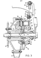
- a brake caliper assembly 10 is supported loosely on the axle 2 by a collar 11 entered in a central bore 12 in an outer caliper member 13 of the assembly, the collar 11 being fixedly held between the end of the rear fork member 1 and the ball bearing 9 opposed thereto.
- a barrel-shaped supporting member 14 extending inwards from the inner end of the collar 11 is practically in contact with an inner caliper member 15 of the caliper assembly so as to support it from its inner peripheral surface at a zone that contains the ball bearing 9 adjacent the member 14/collar 11.
- the two caliper members 13,15 carry at least one pair of brake pads 16,16 on surfaces opposed to the disc 7, and a caliper piston 17 that acts on one of the pads 16,16. By advancing movement of the piston 17 the two pads 16,16 are caused to close to grip the disc 7 therebetween in conventional fashion.
- the pads 16,16 are located by a pin 18, and bolts 19 secure the two caliper members 13,15 to each other.
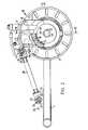
- a torque link 20 disposed substantially tangentially of the brake disc 7.
- Each end of this torque link 20 is supported, via a bush 21, on a pin 23, each bush 21 being composed of two rigid layers with a rubber layer 22 therebetween so that a resilient bush is formed as a whole.
- the pin 23 is secured in a lug 24 projecting from the caliper assembly 10.
- the pin 23 is secured in a lug 25 extending from the fork member 1.
- the caliper assembly 10 has between its two caliper members 13, 15, the barrel-shaped supporting member 14. As shown in Figure 3, this member 14 has the collar 11 inserted in its central bore and is fixed thereto by welding or some other means. As an alternative, a supporting member 14A as illustrated in Figure 5 can be mounted directly on the axle 2 (entered in the central bore of the supporting member), the member 14A being held between the collar 11 and the adjacent ball bearing 9.
- the brake caliper assembly 10 is supported at its central bore 12 on one side by the axle 2 at a zone that has a radial plane common with the zone at which the torque link 20 is connected to the assembly 10, and at an internal peripheral surface on the other side by the supporting member 14 or 14A at a zone that has a radial plane common with the brake disc 7.
- Forces acting on the caliper assembly 10 during braking are a braking force A developed at the brake disc 3 and a reaction force B developed at the connection with the torque link 20, but as the two places at which the assembly 10 is supported, and which are relatively widely distanced apart, are respectively in line with, or substantially in line with, the points at which the lines of application of these forces A and B pass through the axle 2, the assembly 10 is held stably.
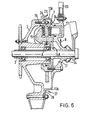
- the outer caliper member 13 includes a portion formed as an annular cover for other parts of the disc brake assembly, the radially outer peripheral part of the caliper member 13 terminating in an inwardly directed flange 13A that terminates in overlapping relationship with an annular flange 26 projecting outwardly from the wheel hub 3, so that a labyrinth seal zone 27 is provided where the flanges 13A and 26 overlap one another.
- the inner caliper member 15, the brake disc 7 and the brake pads 16,16 are all contained within this zone 27 and hence are protected from muddy water and the like, whereby the service life of the disc and the pads tends to be lengthened.
- This single caliper member 28 has a central hub portion 29 that is elongated axially, the caliper member 28 being supported on the collar 11 which is entered in a central bore 30 of the central hub portion 29.
- the axial length of the hub portion 29, and hence of the bore 30, is such that the caliper assembly 10A is supported, inter alia, where the lines of application of the braking force A and the reaction force B, developed during braking, pass through the axle 2.
- the bore 30 extends from a zone having a radial plane common with the brake disc 7 to beyond a zone having a radial plane common with the zone at which the torque link 20 is connected to the assembly 10A.
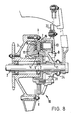
- the ball bearing member 9 nearest the collar 11 the zone at which the support member 14 supports the inner caliper member 15, and the brake disc 7 are disposed so as to have a common-radial plane X-X that passes through the centre of the brake disc 2 and substantially through the centres of the zone at which the support member 14 supports the inner caliper member 15 (see point Y in Figure 8) and of the bearing member 9 nearest the collar 11 (point Z).
- friction force (the braking force A) generated between the disc 2 and the pads 16,16 acts on the bearing member 9 nearest the collar 11 through the wheel hub 3 so far as the disc 2 side is concerned, and as there is no overhanging relationship between the disc 2 and the bearing member 9 there is no moment increase in this force and the bearing member 9 gives stable support without the occurrence of twist.
- the braking force A acts on the support member 14 through the inner caliper member 15 so far as the pads 16,16 side is concerned, and as the point Y is substantially co-planar with the centre of the disc 2, .no moment increase in force occurs, so that no twist is produced.
- the grease in the chamber 31 libricates the sliding surfaces on which the brake caliper assembly is supported.
Abstract
Description
- This invention relates to disc brakes for motorcycles and other two-wheeled vehicles.
- It has been proposed to provide rotatably on one end portion of an axle a wheel hub having a peripheral brake disc and with a central hollow shaft supported on the axle; and to provide on the other end portion of the axle a brake caliper assembly with the axle inserted in a central bore of this assembly, the caliper assembly being supported on the axle only at a place near one side of the assembly. In such a construction, whereas the caliper assembly is supported only near one side, external force from the brake disc during braking operation acts on the caliper assembly at a place near its other side, thus involving the disadvantage that twisting can easily develop and stable braking operation is difficult to obtain.
- According to the present invention there is provided a disc brake assembly comprising a brake disc peripherally carried by the hub of the wheel to be braked, and a brake caliper assembly, the hub and the caliper assembly being mounted side-by-side on an axle for the wheel with the axle passing through a central hollow shaft of the hub and through a central bore of the caliper assembly; characterised in that the caliper assembly is supported from the axle at two places that are relatively widely distanced apart. As in this construction the brake caliper assembly is supported at two places that are relatively widely distanced apart, the assembly is stably supported in a manner to resist twisting during braking. The stable support can be enhanced in various ways as will be described hereinbelow.
- It has also been previously proposed to provide rotatably on one end portion of an axle a wheel hub having a peripheral brake disc and with a central hollow shaft supported on the axle; to provide on the other end portion of the axle a brake caliper assembly with the axle inserted in a central bore of the caliper assembly; and to couple the caliper assembly with the frame of the motorcycle or other vehicle - through a torque link extending substantially tangentially of the brake disc. The caliper assembly is slidable on the axle in proportion to wear on each brake pad opposing the disc, and it is preferable that the torque link should be able smoothly to follow this movement of the caliper assembly. To achieve this, as will be made clear hereinafter, the present invention further provides, in a disc brake assembly as already defined, a torque link for connection between the brake caliper assembly and a member of the frame of a vehicle in which the disc brake assembly is to be fitted, the disc brake assembly being further characterised in that a resilient bush including an intermediate rubber layer is provided at each end of the torque link, the torque link being connected to the caliper assembly and to the vehicle frame member via these resilient bushes.
- In addition in a disc brake assembly as already defined, and in which the caliper assembly includes outer and inner caliper members, the invention provides that the outer caliper member includes a portion formed as an annular cover for the inner caliper member and the brake disc and pads of the disc brake assembly, preferably, in this case, the annular cover co-operates with an annular flange carried by the inner caliper member to form a labyrinth seal zone.
- Furthermore provision can be made for the brake caliper assembly of the disc brake assembly to contain lubricating medium.
- For a better understanding of the invention and to show how the same may be carried into effect, reference will now be made, by way of example, to the accompanying drawings, in which:-
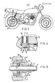
- Figure 1 is a somewhat schematic side view of a motorcycle,
- Figure 2 is a side view, partly cut away and in section and drawn to a larger scale, of a disc brake assembly and associated components of the motorcycle of Figure 1,
- Figure 3 is a sectional view taken on the line III-III in Figure 2,
- Figure 4 is a detail sectional view taken on the line IV-IV in Figure 2, and
- Figures 5 to 9 are sectional side views each of part of a disc brake assembly and associated components as shown in Figure 3 but illustrating different forms.
- Referring first to Figures 1 to 4 of the drawings, in the region of the rear wheel of the motorcycle (or other two-wheeled vehicle), the frame includes a rear fork member 1 supporting one end of the
rear wheel axle 2. Arear wheel hub 3 having a central hollow shaft 4 is provided with asprocket 5 on its periphery and a further sprocket 6 at one end. Anannular brake disc 7 is fixed to thehub 3 by bolts andnuts 8. The hollow shaft 4 is supported on theaxle 2 by a pair ofball bearings - A
brake caliper assembly 10 is supported loosely on theaxle 2 by acollar 11 entered in acentral bore 12 in anouter caliper member 13 of the assembly, thecollar 11 being fixedly held between the end of the rear fork member 1 and the ball bearing 9 opposed thereto. A barrel-shaped supportingmember 14 extending inwards from the inner end of thecollar 11 is practically in contact with aninner caliper member 15 of the caliper assembly so as to support it from its inner peripheral surface at a zone that contains the ball bearing 9 adjacent themember 14/collar 11. - The two
caliper members brake pads disc 7, and acaliper piston 17 that acts on one of thepads piston 17 the twopads disc 7 therebetween in conventional fashion. Thepads pin 18, andbolts 19 secure the twocaliper members - Between the disc brake assembly components so far described and a part of the rear fork member 1 remote from the components there extends a
torque link 20, disposed substantially tangentially of thebrake disc 7. Each end of thistorque link 20 is supported, via abush 21, on apin 23, eachbush 21 being composed of two rigid layers with arubber layer 22 therebetween so that a resilient bush is formed as a whole. At the brake end thepin 23 is secured in alug 24 projecting from thecaliper assembly 10. At the rear fork member end thepin 23 is secured in alug 25 extending from the fork member 1. - The components so far described operate as follows. By closing the two
pads caliper piston 17, thebrake disc 7 is gripped from both sides to effect braking. Braking torque generated therefrom is transmitted through thetorque link 20 to the rear fork and therefore to the frame of the motorcycle, all in a manner as previously proposed, However, in the present construction as eachpad 16 becomes worn, and thecaliper assembly 10 moves on theaxle 2 correspondingly to compensate for this wear, in which case thetorque link 20 tends to oscillate somewhat laterally, such oscillation is absorbed by therubber layers 22 of thebushes 21 and hence thetorque link 20 is able smoothly to follow this movement of thecaliper assembly 10. - As has already been described, the
caliper assembly 10 has between its twocaliper members member 14. As shown in Figure 3, thismember 14 has thecollar 11 inserted in its central bore and is fixed thereto by welding or some other means. As an alternative, a supportingmember 14A as illustrated in Figure 5 can be mounted directly on the axle 2 (entered in the central bore of the supporting member), themember 14A being held between thecollar 11 and the adjacent ball bearing 9. In either case, in operation as the twopads brake caliper assembly 10 is supported at itscentral bore 12 on one side by theaxle 2 at a zone that has a radial plane common with the zone at which thetorque link 20 is connected to theassembly 10, and at an internal peripheral surface on the other side by the supportingmember brake disc 7. Forces acting on thecaliper assembly 10 during braking are a braking force A developed at thebrake disc 3 and a reaction force B developed at the connection with thetorque link 20, but as the two places at which theassembly 10 is supported, and which are relatively widely distanced apart, are respectively in line with, or substantially in line with, the points at which the lines of application of these forces A and B pass through theaxle 2, theassembly 10 is held stably. This is also the case in the form shown in Figure 6 in which theouter caliper member 13 includes a portion formed as an annular cover for other parts of the disc brake assembly, the radially outer peripheral part of thecaliper member 13 terminating in an inwardly directedflange 13A that terminates in overlapping relationship with anannular flange 26 projecting outwardly from thewheel hub 3, so that alabyrinth seal zone 27 is provided where theflanges inner caliper member 15, thebrake disc 7 and thebrake pads zone 27 and hence are protected from muddy water and the like, whereby the service life of the disc and the pads tends to be lengthened. - It-is also to be noted that in this form the
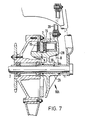
collar 11 and supportingmember 14 are replaced by a one-piece collar and support 14A having, overall, effectively the same configuration as the collar fl and supportingmember 14 taken together. - The problem of twisting occurring in operation has already been discussed above, and it has been described how, in the brake caliper assemblies so far described with reference to the accompanying drawings, to resist twisting,support is provided at two places that are relatively widely distanced apart. In the form of Figure 7 there is also, inter alia, support at two places that are relatively widely distanced apart, but in this case there is continuous support between these places. In this form the
brake caliper assembly 10A has only onecaliper member 28 which carries not only thecaliper piston 17 of the assembly and one of thepads 16, but also theother pad 16. Thissingle caliper member 28 has acentral hub portion 29 that is elongated axially, thecaliper member 28 being supported on thecollar 11 which is entered in acentral bore 30 of thecentral hub portion 29. The axial length of thehub portion 29, and hence of thebore 30, is such that thecaliper assembly 10A is supported, inter alia, where the lines of application of the braking force A and the reaction force B, developed during braking, pass through theaxle 2. To this end, thebore 30 extends from a zone having a radial plane common with thebrake disc 7 to beyond a zone having a radial plane common with the zone at which thetorque link 20 is connected to theassembly 10A. - Further to improve the support of the
caliper assembly 10, in the form shown in Figure 8, theball bearing member 9 nearest thecollar 11, the zone at which thesupport member 14 supports theinner caliper member 15, and thebrake disc 7 are disposed so as to have a common-radial plane X-X that passes through the centre of thebrake disc 2 and substantially through the centres of the zone at which thesupport member 14 supports the inner caliper member 15 (see point Y in Figure 8) and of thebearing member 9 nearest the collar 11 (point Z). In braking operation, friction force (the braking force A) generated between thedisc 2 and thepads member 9 nearest thecollar 11 through thewheel hub 3 so far as thedisc 2 side is concerned, and as there is no overhanging relationship between thedisc 2 and the bearingmember 9 there is no moment increase in this force and the bearingmember 9 gives stable support without the occurrence of twist. Similarly, and as already discussed,as the braking force A acts on thesupport member 14 through theinner caliper member 15 so far as thepads disc 2, .no moment increase in force occurs, so that no twist is produced. - Finally, in the form shown in Figure 9 there is only a
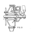
single caliper member 28A as in the case of the form of figure 7, but here support for this member utilises the one-piece collar andsupport member 14A of the form of Figure 6. Between thismember 14A and thecaliper member 28A there is achamber 31 that is filled with grease or other libricant, this chamber being sealed at each end by an 0-ring seal Similar chambers 31 that can be filled with grease are provided in the forms of Figures 3,5,6 and 8 and Figures 3,6 and 8 also illustrate asealing boot 34 that can be fitted in addition to the 0-ring seal 32 (Figures 3 and 8) or instead of the seal 32 (Figure 6). - In operation, the grease in the
chamber 31 libricates the sliding surfaces on which the brake caliper assembly is supported.
Claims (9)
Applications Claiming Priority (12)
| Application Number | Priority Date | Filing Date | Title |
|---|---|---|---|
| JP8232/79U | 1979-01-27 | ||
| JP1979008232U JPS6137866Y2 (en) | 1979-01-27 | 1979-01-27 | |
| JP1979071324U JPS6137867Y2 (en) | 1979-05-29 | 1979-05-29 | |
| JP6552979A JPS55159336A (en) | 1979-05-29 | 1979-05-29 | Disk brake |
| JP7132379A JPS5526284A (en) | 1978-06-09 | 1979-05-29 | Cleaning apparatus of spinning nozze clasp |
| JP71323/79U | 1979-05-29 | ||
| JP7132279U JPS612357Y2 (en) | 1979-05-29 | 1979-05-29 | |
| JP65529/79U | 1979-05-29 | ||
| JP71322/79U | 1979-05-29 | ||
| JP71324/79U | 1979-05-29 | ||
| JP75926/79U | 1979-06-06 | ||
| JP7592679U JPS614745Y2 (en) | 1979-06-06 | 1979-06-06 |
Publications (2)
| Publication Number | Publication Date |
|---|---|
| EP0014101A1 true EP0014101A1 (en) | 1980-08-06 |
| EP0014101B1 EP0014101B1 (en) | 1983-03-30 |
Family
ID=27548110
Family Applications (1)
| Application Number | Title | Priority Date | Filing Date |
|---|---|---|---|
| EP19800300237 Expired EP0014101B1 (en) | 1979-01-27 | 1980-01-25 | Disc brakes |
Country Status (1)
| Country | Link |
|---|---|
| EP (1) | EP0014101B1 (en) |
Cited By (7)
| Publication number | Priority date | Publication date | Assignee | Title |
|---|---|---|---|---|
| FR2498712A1 (en) * | 1981-01-24 | 1982-07-30 | Honda Motor Co Ltd | IMPROVED DISC BRAKE FOR MOTORCYCLE |
| FR2510691A2 (en) * | 1981-01-24 | 1983-02-04 | Honda Motor Co Ltd | IMPROVED DISC BRAKE FOR MOTORCYCLE |
| EP0718182A1 (en) * | 1994-12-24 | 1996-06-26 | FICHTEL & SACHS AG | Bicycle disc brake |
| WO2000043222A1 (en) * | 1999-01-25 | 2000-07-27 | Laurent Pidoux | Hub for motorcycle or the like for making the wheel reversible in its support |
| US6443267B1 (en) * | 2000-08-01 | 2002-09-03 | Daniel P. Burbank | Wheelbarrow disk brake assembly |
| EP1855024A1 (en) * | 2006-05-10 | 2007-11-14 | Meritor Heavy Vehicle Braking Systems (UK) Limited | Wheel brake actuator |
| WO2016203323A1 (en) * | 2015-02-18 | 2016-12-22 | Alter Ego S.A.S. | A brake caliper assembly and an associated support structure for disk brakes |
Citations (13)
| Publication number | Priority date | Publication date | Assignee | Title |
|---|---|---|---|---|
| FR1307621A (en) * | 1961-12-06 | 1962-10-26 | Improvements to disc brakes | |
| FR1315950A (en) * | 1961-12-15 | 1963-01-25 | Disc braking device incorporated in a hub, more especially intended for mopeds and similar two-wheeled vehicles | |
| FR81127E (en) * | 1962-02-09 | 1963-08-02 | Disc braking device incorporated in a hub, more especially intended for mopeds and similar two-wheeled vehicles | |
| DE1267041B (en) * | 1964-09-22 | 1968-04-25 | Teves Gmbh Alfred | Either hydraulically or mechanically operated partially lined disc brake |
| FR2007791A1 (en) * | 1968-05-03 | 1970-01-09 | Fischer Ag Georg | |
| FR2131489A5 (en) * | 1971-03-29 | 1972-11-10 | Bendix Corp | |
| US3817342A (en) * | 1973-05-14 | 1974-06-18 | Rokon Inc | Motorcycle brakes |
| FR2260028A1 (en) * | 1974-02-05 | 1975-08-29 | Campagnolo Tullio | |
| FR2260029A1 (en) * | 1974-02-05 | 1975-08-29 | Campagnolo Tullio | |
| FR2289389A1 (en) * | 1974-10-31 | 1976-05-28 | Zeppellini Serge | Disc brake for motor cycle - with brake pads spaced around disc for even brake force (BE300476) |
| FR2306370A1 (en) * | 1975-03-29 | 1976-10-29 | Klaue Hermann | DOUBLE DISC BRAKE, ESPECIALLY FOR MOTORCYCLES |
| FR2321073A2 (en) * | 1975-08-14 | 1977-03-11 | Campagnolo Tullio | DISC BRAKE FOR VEHICLE WHEELS, ESPECIALLY MOTORCYCLES |
| DE2617241A1 (en) * | 1975-03-29 | 1977-11-10 | Klaue Hermann | Twin disc brake for motorcycle - has brake cylinders replaced by interacting expandable ring profiles within hub |
-
1980
- 1980-01-25 EP EP19800300237 patent/EP0014101B1/en not_active Expired
Patent Citations (13)
| Publication number | Priority date | Publication date | Assignee | Title |
|---|---|---|---|---|
| FR1307621A (en) * | 1961-12-06 | 1962-10-26 | Improvements to disc brakes | |
| FR1315950A (en) * | 1961-12-15 | 1963-01-25 | Disc braking device incorporated in a hub, more especially intended for mopeds and similar two-wheeled vehicles | |
| FR81127E (en) * | 1962-02-09 | 1963-08-02 | Disc braking device incorporated in a hub, more especially intended for mopeds and similar two-wheeled vehicles | |
| DE1267041B (en) * | 1964-09-22 | 1968-04-25 | Teves Gmbh Alfred | Either hydraulically or mechanically operated partially lined disc brake |
| FR2007791A1 (en) * | 1968-05-03 | 1970-01-09 | Fischer Ag Georg | |
| FR2131489A5 (en) * | 1971-03-29 | 1972-11-10 | Bendix Corp | |
| US3817342A (en) * | 1973-05-14 | 1974-06-18 | Rokon Inc | Motorcycle brakes |
| FR2260028A1 (en) * | 1974-02-05 | 1975-08-29 | Campagnolo Tullio | |
| FR2260029A1 (en) * | 1974-02-05 | 1975-08-29 | Campagnolo Tullio | |
| FR2289389A1 (en) * | 1974-10-31 | 1976-05-28 | Zeppellini Serge | Disc brake for motor cycle - with brake pads spaced around disc for even brake force (BE300476) |
| FR2306370A1 (en) * | 1975-03-29 | 1976-10-29 | Klaue Hermann | DOUBLE DISC BRAKE, ESPECIALLY FOR MOTORCYCLES |
| DE2617241A1 (en) * | 1975-03-29 | 1977-11-10 | Klaue Hermann | Twin disc brake for motorcycle - has brake cylinders replaced by interacting expandable ring profiles within hub |
| FR2321073A2 (en) * | 1975-08-14 | 1977-03-11 | Campagnolo Tullio | DISC BRAKE FOR VEHICLE WHEELS, ESPECIALLY MOTORCYCLES |
Cited By (9)
| Publication number | Priority date | Publication date | Assignee | Title |
|---|---|---|---|---|
| FR2498712A1 (en) * | 1981-01-24 | 1982-07-30 | Honda Motor Co Ltd | IMPROVED DISC BRAKE FOR MOTORCYCLE |
| FR2510691A2 (en) * | 1981-01-24 | 1983-02-04 | Honda Motor Co Ltd | IMPROVED DISC BRAKE FOR MOTORCYCLE |
| EP0718182A1 (en) * | 1994-12-24 | 1996-06-26 | FICHTEL & SACHS AG | Bicycle disc brake |
| WO2000043222A1 (en) * | 1999-01-25 | 2000-07-27 | Laurent Pidoux | Hub for motorcycle or the like for making the wheel reversible in its support |
| FR2788724A1 (en) * | 1999-01-25 | 2000-07-28 | Laurent Pidoux | Motorcycle hub, comprises a reversible support this enabling the wheel to be reversible |
| US6736464B1 (en) | 1999-01-25 | 2004-05-18 | Ajp Industrial | Hub for motorcycle or the like permitting rendering reversible the wheel in its support |
| US6443267B1 (en) * | 2000-08-01 | 2002-09-03 | Daniel P. Burbank | Wheelbarrow disk brake assembly |
| EP1855024A1 (en) * | 2006-05-10 | 2007-11-14 | Meritor Heavy Vehicle Braking Systems (UK) Limited | Wheel brake actuator |
| WO2016203323A1 (en) * | 2015-02-18 | 2016-12-22 | Alter Ego S.A.S. | A brake caliper assembly and an associated support structure for disk brakes |
Also Published As
| Publication number | Publication date |
|---|---|
| EP0014101B1 (en) | 1983-03-30 |
Similar Documents
| Publication | Publication Date | Title |
|---|---|---|
| US6883630B2 (en) | Inboard brake system for a straddle-type all-terrain vehicle | |
| US7845473B2 (en) | Brake caliper structure of straddle seat off-road vehicle | |
| US7451857B2 (en) | Seat mount structure for saddle ride type vehicle | |
| KR101294035B1 (en) | Structure of axle assembly for a driving wheel | |
| US4491340A (en) | Vehicle wheel axle and brake mounting assembly | |
| EP0014101B1 (en) | Disc brakes | |
| GB2346125A (en) | Heat shielded mid-roller in an endless-track vehicle | |
| US4343380A (en) | Disk brake assembly | |
| US6729455B2 (en) | Structure and method for supporting electromagnetic coupling | |
| JPH08291866A (en) | Seal for piston and axle assembly | |
| US6318492B1 (en) | Integral knuckle and hub lock | |
| WO2007081074A1 (en) | Disc and wheel bearing assembly of driving wheel | |
| JP3052075B2 (en) | Buggy car braking device | |
| US4500111A (en) | Suspension assembly for a wheel and brake | |
| JPS5989251A (en) | Mounting unit for power transmitting case and brake case in auto tricycle | |
| CA1166290A (en) | Suspension assembly for a wheel and brake | |
| CN101007558A (en) | Bicycle capable of providing drag force for exercise | |
| JPS6137866Y2 (en) | ||
| JP2602998Y2 (en) | Seal structure | |
| SU895757A1 (en) | Vehicle wheel assembly | |
| CN211167089U (en) | Air disc type brake steering front shaft assembly for small and medium-sized passenger car | |
| JPH063223Y2 (en) | Axle seal structure | |
| JPH01122790A (en) | Disk brake gear for rear wheel of motorcycle | |
| JPS6137867Y2 (en) | ||
| JPH0210342Y2 (en) |
Legal Events
| Date | Code | Title | Description |
|---|---|---|---|
| PUAI | Public reference made under article 153(3) epc to a published international application that has entered the european phase |
Free format text: ORIGINAL CODE: 0009012 |
|
| AK | Designated contracting states |
Designated state(s): DE FR GB |
|
| 17P | Request for examination filed |
Effective date: 19801016 |
|
| GRAA | (expected) grant |
Free format text: ORIGINAL CODE: 0009210 |
|
| AK | Designated contracting states |
Designated state(s): DE FR GB |
|
| REF | Corresponds to: |
Ref document number: 3062487 Country of ref document: DE Date of ref document: 19830505 |
|
| ET | Fr: translation filed | ||
| PGFP | Annual fee paid to national office [announced via postgrant information from national office to epo] |
Ref country code: DE Payment date: 19890109 Year of fee payment: 10 |
|
| PGFP | Annual fee paid to national office [announced via postgrant information from national office to epo] |
Ref country code: FR Payment date: 19900124 Year of fee payment: 11 |
|
| PGFP | Annual fee paid to national office [announced via postgrant information from national office to epo] |
Ref country code: GB Payment date: 19900131 Year of fee payment: 11 |
|
| PG25 | Lapsed in a contracting state [announced via postgrant information from national office to epo] |
Ref country code: DE Effective date: 19901002 |
|
| PG25 | Lapsed in a contracting state [announced via postgrant information from national office to epo] |
Ref country code: GB Effective date: 19910125 |
|
| GBPC | Gb: european patent ceased through non-payment of renewal fee | ||
| PG25 | Lapsed in a contracting state [announced via postgrant information from national office to epo] |
Ref country code: FR Effective date: 19910930 |
|
| REG | Reference to a national code |
Ref country code: FR Ref legal event code: ST |
|
| PLBE | No opposition filed within time limit |
Free format text: ORIGINAL CODE: 0009261 |
|
| STAA | Information on the status of an ep patent application or granted ep patent |
Free format text: STATUS: NO OPPOSITION FILED WITHIN TIME LIMIT |