EP0014084A1 - Clou en tôle - Google Patents
Clou en tôle Download PDFInfo
- Publication number
- EP0014084A1 EP0014084A1 EP80300181A EP80300181A EP0014084A1 EP 0014084 A1 EP0014084 A1 EP 0014084A1 EP 80300181 A EP80300181 A EP 80300181A EP 80300181 A EP80300181 A EP 80300181A EP 0014084 A1 EP0014084 A1 EP 0014084A1
- Authority
- EP
- European Patent Office
- Prior art keywords
- head portion
- shank portion
- tabs
- sheet metal
- members
- Prior art date
- Legal status (The legal status is an assumption and is not a legal conclusion. Google has not performed a legal analysis and makes no representation as to the accuracy of the status listed.)
- Granted
Links
- 239000002184 metal Substances 0.000 title claims abstract description 25
- 239000011521 glass Substances 0.000 claims description 2
- 230000000717 retained effect Effects 0.000 claims 1
- 230000004323 axial length Effects 0.000 description 6
- 239000012774 insulation material Substances 0.000 description 4
- 238000009413 insulation Methods 0.000 description 2
- 239000000463 material Substances 0.000 description 2
- 238000000034 method Methods 0.000 description 2
- 229910000639 Spring steel Inorganic materials 0.000 description 1
- 230000003116 impacting effect Effects 0.000 description 1
- 230000008676 import Effects 0.000 description 1
- 238000004519 manufacturing process Methods 0.000 description 1
- 238000003466 welding Methods 0.000 description 1
Images

Classifications
-
- F—MECHANICAL ENGINEERING; LIGHTING; HEATING; WEAPONS; BLASTING
- F16—ENGINEERING ELEMENTS AND UNITS; GENERAL MEASURES FOR PRODUCING AND MAINTAINING EFFECTIVE FUNCTIONING OF MACHINES OR INSTALLATIONS; THERMAL INSULATION IN GENERAL
- F16B—DEVICES FOR FASTENING OR SECURING CONSTRUCTIONAL ELEMENTS OR MACHINE PARTS TOGETHER, e.g. NAILS, BOLTS, CIRCLIPS, CLAMPS, CLIPS OR WEDGES; JOINTS OR JOINTING
- F16B15/00—Nails; Staples
- F16B15/06—Nails; Staples with barbs, e.g. for metal parts; Drive screws
Definitions
- the present invention relates to a metal nail.
- Sheet metal nails for securing panels or the like to a support structure are well-known in the prior art.
- sheet metal nails are well known for attaching slabs of insulation or the like to metallic roof decks or the like.
- One type of prior art sheet metal nail is a one-piece structure utilizing an integral head and shank portion.
- Such nails are extremely desirable for many applications wherein the required surface area of the head portion and/or the axial length of the shank portion does not exceed certain limits.
- the stamping procedures to produce same are unduly difficult, and/or expensive, and/or the nails are not easily and/or compactly shipped.
- the prior art has also included multiple-piece sheet metal nails which are useful when an especially large axial length of shank portion and/or surface area of head portion is required.
- the prior art multiple-piece nails are not totally satisfactory as they require preassembly as by a welding or fabrication operation and an unduly large shipping container. Also, they are difficult to assemble properly in the work place, and/or they require specialized assembly tools.
- the present invention provides a sheet metal nail characterized by a one-piece shank portion and a one-piece head portion which are manually self-retainingly assembleable to form the nail, said shank portion and said head portion each defining engaging means adapted to be non-threadably self-retainingly interengaged upon a fractional turn rotation of said shank portion relative to said head portion.
- a sheet metal nail according to the invention may be compactly shipped and quickly, manually, assembled without the use of special tools.
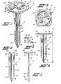
- a two-piece nail 10 of the present invention may be seen in the assembled condition by reference to FIGS. 1 through 3.
- the two-piece nail 10 comprises a one-piece shank portion 12 and a one-piece head portion 14, each of which may be shipped separately and then manually, self-lockingly assembled at the work place.
- the shank portion 12 may be of a convenient, axial length L and shank portions of various axial lengths may be provided for assembly each to a standard head portion 14.
- head portion 14 may be of a convenient shape and/or surface area and head portions of various shapes and/or surface areas may be provided for assembly to a standard length shank portion 12 or to shank portions 12 of various axial lengths.
- the shank portion 12 comprises a generally elongated body which may be generally arcuate in cross sectional shape or may be substantially flat with an axially extending rib 16 pressed therein to provide additional rigidity. "- The free end of the shank portion, or the leading end, is provided with a generally V-shaped edge 18 for piercing the material into which the nail is to be driven. Of course, any type of a pointed ledging edge is sufficient for this purpose.
- a plurality of locking members or tangs 20 are provided in the shank at different distances from the head portion 14.
- the locking members are arranged in two aligned rows running parallel to the axis of the shank portion and provision of same at various axial spacings from the head portion allows the nail 10 to be utilized with-insulation materials and/or deck materials of various thicknesses.
- the locking members 20 illustrated are of the cam locking type comprising upwardly and outwardly extending members formed from inverted V-or U-shaped slots in the shank. It is understood that various types and numbers of locking members such as 20 may be utilized in the nail being described.
- a pair of protuberances or protrusions 22 are formed in the shank adjacent the leading edge 18 thereof and are aligned with the rows of locking members 20.
- the protrusions 22 extend from the same surface of the shank portion as do the locking members and are aligned therewith.
- the head portion 14 is in the form of a generally flat plate defining an upper surface 24 and a lower surface 26.
- the surfaces 24 and 26 of the head portion 14 may be substantially flat, or preferably, may be formed with rib members such as annular rib member 28 and generally radially extending rib members 30 for additional rigidity.
- an impacting tool such as a hammer
- the shank portion 12 and the head portion 14 are of a sheet metal, such as spring steel, and are of a gauge sufficient to meet the requirement of the nail 10.
- the head portion and the shank portion are formed as stampings.
- the one-piece stamped shank portion 12 may be seen in greater detail by reference to FIGS. 4 through 6. Extending generally transversely outwardly and in opposite directions from the end of the shank portion opposite the leading end 18 are a pair of generally coplanar wing members 32 and 34 formed from bent over extensions of the shank portions 12. The wing members 32 and 34 extend from opposite sides of the shank portion 12 at right angles. These projections are separated by a distance 40 measured in the plane defined by the upper surface of the wings. The projections may be of a dimple shape or, preferably, may be generally chevron shaped slots sheared from the wing members. The wing members 32 and 34 are of a thickness 42 which is generally equal to the thickness of the stock from which the shank portion 12 is formed. A gusset may be formed between the wing members and the longitudinally extending section of the shank portion.
- the one-piece head portion 14 may be seen in greater detail by reference to FIGS. 7 and 8.
- the head portion 14 is a generally flat plate having an upper surface 24 and a lower surface 26.
- the head portion may be proveded with ribs such as ribs 28 and 30 for added rigidity.
- the head portion 14 is provided with a generally centrally located aperture or opening 44 which is preferably of a generally hour glass shape.
- the opening 44 is sized to allow passage of the axially extending section of the shank portion 12 but to prevent passage of the wing members, 32 and 34, and to allow at least limited rotation of the shank portion 12 relative to the head portion 14 when the shank portion 12 is inserted into the aperture 44.
- tabs 46 and 48 Located on diametrically opposite sides of opening 44 are two tabs 46 and 48 which are sheared out of the body of the head portion 14 and extend generally parallel to the upper surface 24.
- the tabs 46 and 48 are spaced from the upper surface 24 by a distance 50 which is generally equal to or slightly less than the thickness 42 of the wing members.
- the free ends of tabs 46 and 48 extend in opposite directions.
- the free ends of the tabs may be provided with generaily upwardly extending lead-in ramps 52.
- the tabs 46 and 48 are each provided with a generally chevron shaped aperture, 54 and 56, respectively, which are separated by a distance 58 generally equal to the distance 40 separating the projections 36 and 38 on the wing members.
- the apertures, 54 and 56 are generally slightly larger than and of the same general shape as the projections 36 and 38.
- the projections 36 and 38 and the apertures 54 and 56 may be of any convenient size and shape and the apertures may be formed in the wing members with the projections formed in the tabs if desired.
- FIG. 9 Assembly of the shank portion 12 to the head portion 14 to form the two-piece nail 10 may be appreciated by reference to FIG. 9 taken in connection with the following description.
- the shank portion 12 is inserted into and through the aperture 44 of the head portion 14, leading edge 18 first, until the wing members, 32 and 34, of the shank portion 12 engage the upper surface 24 of the head portion 14 as may be seen by reference to the dotted line illustration in FIG. 9.
- the shank 12 is then rotated in a counterclockwise direction relative to the head portion 14 causing the wing members 32 and 34 to engage the lead-in ramps 52 of the free ends of the tabs, 46 and 48, causing the tabs to deflect resiliently upwardly as the projections 36 and 38 on the wing members pass between the tabs and the upper surface 24.
- the projections may be in the form of generally continuous dimples and the apertures of a generally annular or circular form. Alternatively, the projections may be eliminated if a self locking assemblage is not required.
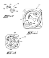
- FIG. 10 A further embodiment of the present invention is shown in Figs. 10, 11 and 12. This is similar to assembly 10 shown in Figs. 1 to 9 and corresponding elements are indicated by the same reference numerals increased by 100.
- the one-piece stamped shank portion 112 of the two-piece nail 100 is illustrated in Fig. 10 and is substantially identical to shank portion 12 discussed above except for the addition of finger members 180 and 182 extending from wing members 132 and 134 respectively.
- the finger members 180 and 182 are of the same thickness as the remainder of the wing members from which they extend and may be tapered towards the free ends thereof.
- the finger members 180 and 182 extend from the wing members 132 and 134, respectively, in a direction opposite the free ends of the chevron shaped projections, 136 and 138, respectively.
- the one-piece stamped head portion 114 is illustrated in Fig. 11 and is substantially identical to head portion 14 described above except for the provision of slots 184 and 186 which are provided in the attached ends of tabs 146 and 148, respectively. Slots 184 and 186 are each of sufficient size to permit passage of finger members 180 and 182, respectively, therethrough.
- the assembled two-piece nail 100 is illustrated in Fig. 12.
- the finger members 180 and 182 extend through slots 184 and 186, respectively, and will cooperate with the tabs 146 and 148 and the upper surface 124 of the head portion 114 to resist movement of the wing members 132 and 134 relative to the head member 114 during driving of the nail 100.
Landscapes
- Engineering & Computer Science (AREA)
- General Engineering & Computer Science (AREA)
- Mechanical Engineering (AREA)
- Connection Of Plates (AREA)
- Portable Nailing Machines And Staplers (AREA)
- Joining Of Building Structures In Genera (AREA)
Applications Claiming Priority (2)
| Application Number | Priority Date | Filing Date | Title |
|---|---|---|---|
| US6409 | 1979-01-25 | ||
| US06/006,409 US4289058A (en) | 1979-01-25 | 1979-01-25 | Sheet metal nail |
Publications (2)
| Publication Number | Publication Date |
|---|---|
| EP0014084A1 true EP0014084A1 (fr) | 1980-08-06 |
| EP0014084B1 EP0014084B1 (fr) | 1982-03-24 |
Family
ID=21720721
Family Applications (1)
| Application Number | Title | Priority Date | Filing Date |
|---|---|---|---|
| EP80300181A Expired EP0014084B1 (fr) | 1979-01-25 | 1980-01-21 | Clou en tôle |
Country Status (5)
| Country | Link |
|---|---|
| US (1) | US4289058A (fr) |
| EP (1) | EP0014084B1 (fr) |
| JP (1) | JPS55103109A (fr) |
| CA (1) | CA1120294A (fr) |
| DE (1) | DE3060234D1 (fr) |
Cited By (1)
| Publication number | Priority date | Publication date | Assignee | Title |
|---|---|---|---|---|
| WO1984000991A1 (fr) * | 1982-09-07 | 1984-03-15 | Eskil Johansson | Organe d'attache |
Families Citing this family (21)
| Publication number | Priority date | Publication date | Assignee | Title |
|---|---|---|---|---|
| JPS616011U (ja) * | 1984-06-18 | 1986-01-14 | 日本ドライブイツト株式会社 | 軽量材止着用の打ち込みアンカ− |
| DE3634038A1 (de) * | 1986-10-06 | 1988-04-14 | Peter Bertsche | Stahlstift zum verbinden von holzteilen |
| CH681134A5 (fr) * | 1989-12-21 | 1993-01-29 | Christiane Caillat | |
| US5509769A (en) * | 1994-10-12 | 1996-04-23 | Illinois Tool Works Inc. | Barbed light weight concrete fastener and plate |
| GB0019786D0 (en) * | 2000-08-12 | 2000-09-27 | Ollis William H | Method of manufacturing connecting devices |
| US7410137B2 (en) * | 2003-08-18 | 2008-08-12 | At&T Delaware Intellectual Property, Inc. | Support device |
| US6957717B1 (en) | 2003-08-22 | 2005-10-25 | Bellsouth Intellectual Property Corp. | Powder driven support device |
| US7077612B1 (en) | 2003-08-22 | 2006-07-18 | Bellsouth Intellectual Property Corp. | Split p-hook |
| US6969039B1 (en) * | 2003-08-22 | 2005-11-29 | Bellsouth Intellectual Property Corp. | Driving device for support device |
| US7014087B1 (en) | 2003-10-16 | 2006-03-21 | Bellsouth Intellectual Property Corporation | Support guide for powder driver barrel |
| US7469865B2 (en) * | 2005-06-15 | 2008-12-30 | Pete Mayorga | Sprinkler anchor |
| US20070098522A1 (en) * | 2005-10-11 | 2007-05-03 | Kim Steve S | Retractable nail device |
| US20080131233A1 (en) * | 2006-10-17 | 2008-06-05 | Yao Chun I | Plate-shaped fastener device |
| US8303228B2 (en) * | 2008-06-13 | 2012-11-06 | Illinois Tool Works Inc. | Metal to metal cleat |
| US20100008717A1 (en) * | 2008-07-10 | 2010-01-14 | Frank Koch | Wall Fastener with Knife Blade and a String |
| US8303227B2 (en) * | 2008-10-06 | 2012-11-06 | The Monadnock Company | Lining fasteners and methods and apparatus therefor |
| US8931993B2 (en) * | 2008-10-06 | 2015-01-13 | The Monadnock Company | Lining fasteners and methods and apparatus therefor |
| US20120114449A1 (en) * | 2010-11-09 | 2012-05-10 | Farrell Mark A | Fastener |
| DE102011106186A1 (de) * | 2011-06-10 | 2012-12-13 | Michael Lammert | Dach- oder Fassadennagel zur Befestigung von Dach- oder Fassadenplatten |
| US9624954B2 (en) | 2014-12-17 | 2017-04-18 | Powernail Company | Plural tapered fastener with material receiving inward region |
| USD815560S1 (en) * | 2016-08-26 | 2018-04-17 | Di-Ying Lo | Plant holder |
Citations (5)
| Publication number | Priority date | Publication date | Assignee | Title |
|---|---|---|---|---|
| DE1387047U (fr) * | ||||
| DE393660C (de) * | 1922-09-21 | 1924-04-05 | Frank Humphris | Nagel, Krampe, Bolzen, Haken, Stift, Ziernagel o. dgl. |
| US2319059A (en) * | 1939-04-06 | 1943-05-11 | Tinnerman Products Inc | Fastening device |
| DE1763808U (de) * | 1955-09-29 | 1958-03-27 | Rheinische Nadelfabriken G M B | Nadel oder nagel mit kunststoffkopf. |
| US3088361A (en) * | 1958-11-28 | 1963-05-07 | Hallock Robert Lay | Driven fastener |
Family Cites Families (12)
| Publication number | Priority date | Publication date | Assignee | Title |
|---|---|---|---|---|
| US306874A (en) * | 1884-10-21 | Carriage-top prop | ||
| US1783391A (en) * | 1926-10-30 | 1930-12-02 | Commw Electric Company | Insert |
| US1815098A (en) * | 1931-01-03 | 1931-07-21 | Albert C Earhart | Bolt substitute |
| US2202896A (en) * | 1939-09-15 | 1940-06-04 | Buchner Morris | Doll eye mounting |
| US2427392A (en) * | 1944-11-25 | 1947-09-16 | Oliver C Eckel | Clip |
| US2697857A (en) * | 1946-10-11 | 1954-12-28 | Oliver C Eckel | Clip with locking plate |
| US2929603A (en) * | 1958-07-03 | 1960-03-22 | Gene A Stewart | Corneal clamp |
| US3466967A (en) * | 1968-03-12 | 1969-09-16 | Robert L Hallock | Tapered sheet metal nail |
| US3710672A (en) * | 1971-05-25 | 1973-01-16 | R Hallock | Hollow sheet metal nail |
| JPS48104972U (fr) * | 1972-03-14 | 1973-12-06 | ||
| US3798710A (en) * | 1973-02-09 | 1974-03-26 | G Tinnerman | Sheet metal panel fastener |
| US3983779A (en) * | 1975-03-10 | 1976-10-05 | Eaton Corporation | Nail |
-
1979
- 1979-01-25 US US06/006,409 patent/US4289058A/en not_active Expired - Lifetime
-
1980
- 1980-01-18 CA CA000344014A patent/CA1120294A/fr not_active Expired
- 1980-01-21 EP EP80300181A patent/EP0014084B1/fr not_active Expired
- 1980-01-21 DE DE8080300181T patent/DE3060234D1/de not_active Expired
- 1980-01-23 JP JP587780A patent/JPS55103109A/ja active Granted
Patent Citations (5)
| Publication number | Priority date | Publication date | Assignee | Title |
|---|---|---|---|---|
| DE1387047U (fr) * | ||||
| DE393660C (de) * | 1922-09-21 | 1924-04-05 | Frank Humphris | Nagel, Krampe, Bolzen, Haken, Stift, Ziernagel o. dgl. |
| US2319059A (en) * | 1939-04-06 | 1943-05-11 | Tinnerman Products Inc | Fastening device |
| DE1763808U (de) * | 1955-09-29 | 1958-03-27 | Rheinische Nadelfabriken G M B | Nadel oder nagel mit kunststoffkopf. |
| US3088361A (en) * | 1958-11-28 | 1963-05-07 | Hallock Robert Lay | Driven fastener |
Cited By (2)
| Publication number | Priority date | Publication date | Assignee | Title |
|---|---|---|---|---|
| WO1984000991A1 (fr) * | 1982-09-07 | 1984-03-15 | Eskil Johansson | Organe d'attache |
| US4627777A (en) * | 1982-09-07 | 1986-12-09 | Johansson Eskil T | Attachment means |
Also Published As
| Publication number | Publication date |
|---|---|
| DE3060234D1 (en) | 1982-04-29 |
| CA1120294A (fr) | 1982-03-23 |
| JPS55103109A (en) | 1980-08-07 |
| JPS647242B2 (fr) | 1989-02-08 |
| EP0014084B1 (fr) | 1982-03-24 |
| US4289058A (en) | 1981-09-15 |
Similar Documents
| Publication | Publication Date | Title |
|---|---|---|
| EP0014084A1 (fr) | Clou en tôle | |
| US3983779A (en) | Nail | |
| US4300865A (en) | Blind clip fastener | |
| CA1063980A (fr) | Machine a poser les rivets borgnes | |
| US4488844A (en) | Floating fastener retainer assembly with removable fasteners | |
| US5564248A (en) | Construction hanger and method of making the same | |
| US4653970A (en) | Quarter-turn fastener | |
| CA1106659A (fr) | Ancrage | |
| US5410854A (en) | Connector brackets | |
| US2266049A (en) | Fastener | |
| US20040081537A1 (en) | Attachment clip and attachment structure using same | |
| US4167885A (en) | Sheet metal nail and method for producing same | |
| US4858408A (en) | Hold down clip | |
| US5971686A (en) | Retained fastener | |
| US3511127A (en) | Metal fastening device | |
| GB2153951A (en) | Pre-assembling fasteners to plates | |
| US2629157A (en) | Fastener | |
| GB2240793A (en) | Fastening clips for corrugated cladding | |
| US4168731A (en) | Locking nut and bolt assembly | |
| CN109538618B (zh) | 一种紧固件 | |
| US3969809A (en) | Self-fastening nut, panel assembly and apparatus | |
| US4385431A (en) | Method of securing a stud to an apertured panel | |
| US4776740A (en) | Stud fastener | |
| JPS6157484B2 (fr) | ||
| GB2029921A (en) | Clip |
Legal Events
| Date | Code | Title | Description |
|---|---|---|---|
| PUAI | Public reference made under article 153(3) epc to a published international application that has entered the european phase |
Free format text: ORIGINAL CODE: 0009012 |
|
| AK | Designated contracting states |
Designated state(s): DE FR GB |
|
| 17P | Request for examination filed | ||
| GRAA | (expected) grant |
Free format text: ORIGINAL CODE: 0009210 |
|
| AK | Designated contracting states |
Designated state(s): DE FR GB |
|
| REF | Corresponds to: |
Ref document number: 3060234 Country of ref document: DE Date of ref document: 19820429 |
|
| PGFP | Annual fee paid to national office [announced via postgrant information from national office to epo] |
Ref country code: FR Payment date: 19881220 Year of fee payment: 10 |
|
| PGFP | Annual fee paid to national office [announced via postgrant information from national office to epo] |
Ref country code: DE Payment date: 19881227 Year of fee payment: 10 |
|
| PGFP | Annual fee paid to national office [announced via postgrant information from national office to epo] |
Ref country code: GB Payment date: 19890121 Year of fee payment: 10 |
|
| PG25 | Lapsed in a contracting state [announced via postgrant information from national office to epo] |
Ref country code: GB Effective date: 19900121 |
|
| GBPC | Gb: european patent ceased through non-payment of renewal fee | ||
| PG25 | Lapsed in a contracting state [announced via postgrant information from national office to epo] |
Ref country code: FR Effective date: 19900928 |
|
| PG25 | Lapsed in a contracting state [announced via postgrant information from national office to epo] |
Ref country code: DE Effective date: 19901002 |
|
| REG | Reference to a national code |
Ref country code: FR Ref legal event code: ST |
|
| PLBE | No opposition filed within time limit |
Free format text: ORIGINAL CODE: 0009261 |
|
| STAA | Information on the status of an ep patent application or granted ep patent |
Free format text: STATUS: NO OPPOSITION FILED WITHIN TIME LIMIT |