EP0014060A1 - Appareillage pour contrôler le profil d'un tunnel ou d'une gallerie creusée par une tête de creusement, et machine de creusement de tunnel équippée de cet appareillage - Google Patents
Appareillage pour contrôler le profil d'un tunnel ou d'une gallerie creusée par une tête de creusement, et machine de creusement de tunnel équippée de cet appareillage Download PDFInfo
- Publication number
- EP0014060A1 EP0014060A1 EP80300127A EP80300127A EP0014060A1 EP 0014060 A1 EP0014060 A1 EP 0014060A1 EP 80300127 A EP80300127 A EP 80300127A EP 80300127 A EP80300127 A EP 80300127A EP 0014060 A1 EP0014060 A1 EP 0014060A1
- Authority
- EP
- European Patent Office
- Prior art keywords
- cutting head
- movement
- profile
- template
- tunnel
- Prior art date
- Legal status (The legal status is an assumption and is not a legal conclusion. Google has not performed a legal analysis and makes no representation as to the accuracy of the status listed.)
- Ceased
Links
Images


Classifications
-
- E—FIXED CONSTRUCTIONS
- E21—EARTH DRILLING; MINING
- E21D—SHAFTS; TUNNELS; GALLERIES; LARGE UNDERGROUND CHAMBERS
- E21D9/00—Tunnels or galleries, with or without linings; Methods or apparatus for making thereof; Layout of tunnels or galleries
- E21D9/003—Arrangement of measuring or indicating devices for use during driving of tunnels, e.g. for guiding machines
-
- E—FIXED CONSTRUCTIONS
- E21—EARTH DRILLING; MINING
- E21D—SHAFTS; TUNNELS; GALLERIES; LARGE UNDERGROUND CHAMBERS
- E21D9/00—Tunnels or galleries, with or without linings; Methods or apparatus for making thereof; Layout of tunnels or galleries
- E21D9/10—Making by using boring or cutting machines
- E21D9/1093—Devices for supporting, advancing or orientating the machine or the tool-carrier
Definitions
- This invention relates to an apparatus and method for controlling the profile of an aperture cut by a cutting head capable of traversing movement in two directions and has been particularly designed for use in tunnel cutting machines where accurate tunnel profile is vital.
- the apparatus can also be used for other purposes, e.g. on free-steered track laying mining machines. If the profile is too small, the tunnel shield, when it is advanced, will jam. If this occurs it is an extremely expensive mistake to remedy. Alternatively, if the profile is too large, then excess grout has to be pumped around the segments which are used to line the tunnel. Again, this can be extremely expensive.
- One system is an electronic system and the location of the cutting head is projected onto a screen which is masked with the desired tunnel profile. The success of this apparatus depends upon the skill of the cutting head machine operator, as he must manipulate the cutting head to the confines of the profile mask but no further.
- apparatus for controlling the profile of an aperture cut by a cutting head capable of traversing movement in two directions at right angles to each other comprising means to control the movement of the cutting head in said two directions, a template having an internal profile representing that of the aperture to be cut, a sensing device engageable with the profile of the template, follower means, responsive to movement of the cutting head to.
- sensing device causes relative movement between the sensing device and template in a direction which is related to the direction of movement of the cutting head, said sensing device coming into engagement with the profile of the template when the cutting head has been traversed sufficiently in a particular direction so as to reach its desired profile extremity, and hydraulic sensing equipment which is actuated in response to said sensing device and template coming into engagement, said sensing equipment being effective to over-ride said means controlling the movement of the cutting head to ensure the head does not cut outside its desired profile.
- the apparatus is part of a tunnel cutting machine, which is provided with hydraulic control means for moving a boom -mounted cutting head in vertical and horizontal planes, and with hydraulic sensors for sensing the horizontal and vertical movements of the cutting head, said sensors, through-suitable hydraulic circuitry, translating said movement to the template, which is mounted on a table for movement related to that of the head.
- the sensing device is supported on a stub shaft projecting from an actuator plate which is mounted for universal rocking movement, as a result of engagement between the template and sensing device, in two horizontal -planes at right angles to each other, and associated with the two planes of movement of the cutting head, there being one pair of sensors responsive, respectively, one to rocking movement of the plate in one sense and the other in the opposite sense, in one plane, and a second pair of sensors responsive, respectively, one to rocking movement of the plate in one sense and the other in the opposite sense, in the second plane, the arrangement being such that said plate rocks when said template moves into engagement with the sensing device when an attempt is made to move the cutting head beyond the boundary of said profile.
- the hydraulic control means for the cutting head includes a joystick unit comprising an operating lever and four hydraulic control valves, one associated with a respective quadrant of the profile to be cut, and suitable hydraulic circuitry supplying or venting hydraulic pressure to respective sides of arcing and lifting pilot operated main control valves which operate the respective lifing and arcing piston/cylinder devices of the boom, each of the sensors being associated with a hydraulic control valve means for over-riding the hydraulic control means, either to prevent lifting/lowering or arcing of the boom, or to reverse such movement, dependent on the position of the template relative to the sensing device.
- a joystick unit comprising an operating lever and four hydraulic control valves, one associated with a respective quadrant of the profile to be cut, and suitable hydraulic circuitry supplying or venting hydraulic pressure to respective sides of arcing and lifting pilot operated main control valves which operate the respective lifing and arcing piston/cylinder devices of the boom, each of the sensors being associated with a hydraulic control valve means for over-riding the hydraulic control means, either to prevent lifting/
- the hydraulic control valve means comprise two control valves, one operative when there is pressure in the circuitry as a result-of the joystick operating lever being in an operative position, and the other which is supplied from a second pressure source when the joystick operating lever is in an inoperative position in which there is no such pressure.
- the above described hydraulic control arrangement comprises a pilot control system for the main lifting and arcing valve and cylinder devices for controlling the boom or other device on which the cutting head is mounted.
- diverter valves are provided in the hydraulic control arrangement so that when the joystick operating lever is operated to move the cutting head out of the quadrant associated with the "dead spot", the pressure leading to both sides of both the arcing . and lifting main-control valves will be diverted to one side of the respective control valve and vented or dumped.
- the invention also extends to a method of controlling the profile of an aperture cut by a cutting head, e.g. that of a tunnel cut by a mining machine.
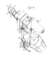
- a mining machine is provided with a cutting head C supported on a boom B which is pivotally supported about a horizontal axis H on a pedestal P under the control of two lifting piston/cylinder devices L.
- the pedestal P can swing about a vertical axis V under the control of two arcing piston/cylinder devices A.
- a template 21 having a profile 23 corresponding to that of a tunnel to be cut by the cutting head C is mounted on a carrier 25 whose movement is controlled by the piston/ cylinder devices 9 and 19.
- the carrier 25 is slidable horizontally on slides 27 under the control of the device 19, and slides 27 are supported on a platform 29 which itself is supported for horizontal sliding movement at right angles to that of carrier 25 on slides 31 supported on a table 33 under the control of device 9. It will thus be appreciated that every movement of the cutting head is translated accurately on a reduced scale to the template 21.
- a cutting head position sensing device 35 is associated, with template 23, the association being such that when template 21 moves to a position corresponding to a point on the periphery of the tunnel profile, the sensing device 35 will engage the profile 23.
- the sensing device 35 is supported on a stub shaft 37 projecting from an actuator plate 39 (see Figure 2) which is mounted for universal rocking movement about any horizontal axis.
- a "joystick” unit forming part of a standard hydraulic control device.
- a Pilot Valve type TH8 RE 64110
- the control lever of the joystick unit is supported on a ball located in a socket and has a cam plate secured to it for rocking movement with the joystick or control lever.
- valves 41,' 43, 45 and 47 Associated with the control lever are four valves 41,' 43, 45 and 47, each having an associated plunger which is actuated by the cam plate on the joystick. For example, when the joystick is moved forwardly to a "lift” position to raise the cutting head C, so the plunger of valve 43 will be actuated. Valve 41 is actuated when the -joystick is moved to its “lower” position, and valves 47 and 45 are actuated when the joystick is moved to "left" and "right” arcing positions.
- valve 41 when valve 41 is actuated, it will move to a position allowing flow of hydraulic fluid from source of pressure 49 into line 51, through a shuttle valve 53 and a vertical template control valve 55 (to be described later) into a line 57, then through a diverter valve 59 into a line 61.
- This line leads to a further vertical template.
- control valve 63 (to be described later) and then to a line 65 which leads to a pilot operated lift control valve 67, which is a pilot operated main control valve for causing actuation of lifting cylinders L for lowering the cutting head C.
- valve 43 when valve 43 is actuated (when the joystick is moved to its "raise” position) it will move to a position allowing flow from pressure source 49 into a line 69, through vertical template control valve 55 into a line 71, through shuttle valve 72 into a line 73, through vertical template control valve 63 into a line 75, through a further diverter valve 77, then into a line 79 leading to the opposite side of lift control valve 67, which will then be moved to a "raise” position, causing actuation of the lifting cylinders L to raise the cutting head C.
- valve 45 when valve 45 is actuated, pressure will be applied to line 80 leading to the R.H.S. of arcing control valve 81, which is a pilot operated main control valve for causing actuation of arcing piston to move cutting head C to the right, cylinder- devices A, and when valve 47 is actuated, pressure will be applied to the line 82 leading to the L.H.S. of control valve 81, to move the cutting head C to the-left.
- Sensor 83 is connected by a yoke both to the control valve 55 and to a further associated control valve 85, and as soon as it is engaged by the actuator plate 39, it will cause the spools of the two control valves 55 and 85 to move from their illustrated position to an intermediate position.
- pressure in the line 51 instead of leading to line 57, is blanked off by the intermediate location of the spool, and the previous pressure in the line 57 which had caused main lift control valve 67 to move to its "lower” position is vented or dumped, through valve 55, line 69, valve 43, and a line 87 to dump 89.
- valve 41 will no longer be actuated, and hence there will be no pressure to control valve 55 to raise the boom when the sensing device 35 causes plate 39 to move the valves 55 and 85 to their third position.
- this problem is solved by the presence of the second control valve 85.
- a similar profile control arrangement is provided whenever the joystick is moved to an "arcing" position or a “raise” position, thus actuating one or a pair of the other valves 43, 45, 47 and subsequently bringing into the control operation the control valve 63 and its associated second control valve 95, and/or one of the pairs of arcing control valves 97 or 99.
- the template profile control circuitry will cause the control valves 97 or 99 and either 55, 85 or 63, 95 associated with the respective profile quadrant, to move to their intermediate positions, thus venting both the lifting and arcing main control valves 67 and 81 and effectively stopping the cutting operation.
- the operator there is no alternative but for the operator to move the joystick away from one of the "45°” positions,- and manually start up the cutting operation again.
- both sides of both the pilot operated lift control valve 67 and the pilot operated arcing control valve 81 are vented, making it impossible to actuate either main control valve.
- eight diverter valves namely the valves 77 and 59, and valves 101, 103, 105, 107, 109 and 111 are provided. These valves allow one side or other of the arcing or lifting sylinders to be pressurised. To achieve this and get away from any one of the four "dead" 45° positions of the cutting tool C and sensing device 35, the operator has to move the joystick completely out of the sector associated with the 45° position of the cutting head C.
- both of the profile control valves 55 and . 85 and the pair of valves 97 will be in their intermediate positions.
- the operator must accordingly move his joystick back past the neutral position either, in a vertical or a horizontal plane so as to cause either lifting or arcing of the cutting tool to move the sensing device 35 away from the profile 23.
- the operator lifts the boom to solve the situation; in doing this he will have to actuate the control valve 43 thus putting pressure into the line 69.
- This pressure when it reaches the template control valve 55 in its intermediate position, will be transferred both to the line 57 and the line 71.
- the line 115 would also lead into a line 125 through the diverter valve 101 to move the diverter valve 111 to its second position in which pressure previously in the line 82 leading to the left hand side of the pilot operated arcing control valve 81 would be vented or dumped. This means that the cutting head can move to the right as called for by movement of the joystick. Thereafter, automatic profile guidance can continue as described previously.
Applications Claiming Priority (2)
| Application Number | Priority Date | Filing Date | Title |
|---|---|---|---|
| GB7901667A GB2039568B (en) | 1979-01-17 | 1979-01-17 | Controlling aperture profile formed by a cutting head |
| GB7901667 | 1979-01-17 |
Publications (1)
| Publication Number | Publication Date |
|---|---|
| EP0014060A1 true EP0014060A1 (fr) | 1980-08-06 |
Family
ID=10502565
Family Applications (1)
| Application Number | Title | Priority Date | Filing Date |
|---|---|---|---|
| EP80300127A Ceased EP0014060A1 (fr) | 1979-01-17 | 1980-01-15 | Appareillage pour contrôler le profil d'un tunnel ou d'une gallerie creusée par une tête de creusement, et machine de creusement de tunnel équippée de cet appareillage |
Country Status (7)
| Country | Link |
|---|---|
| US (1) | US4285546A (fr) |
| EP (1) | EP0014060A1 (fr) |
| AR (1) | AR220437A1 (fr) |
| AU (1) | AU5441280A (fr) |
| BR (1) | BR8000282A (fr) |
| ES (1) | ES487770A0 (fr) |
| GB (1) | GB2039568B (fr) |
Cited By (2)
| Publication number | Priority date | Publication date | Assignee | Title |
|---|---|---|---|---|
| JPS5876698A (ja) * | 1981-11-02 | 1983-05-09 | 日立造船株式会社 | 掘削範囲を規制する装置 |
| CN101713975B (zh) * | 2008-10-08 | 2011-10-05 | 石家庄煤矿机械有限责任公司 | 掘进自动截割成形智能控制系统 |
Families Citing this family (5)
| Publication number | Priority date | Publication date | Assignee | Title |
|---|---|---|---|---|
| US4708395A (en) * | 1984-11-05 | 1987-11-24 | Conoco Inc. | Remotely sensing of excavation cavity during mining |
| AT383651B (de) * | 1985-10-14 | 1987-08-10 | Voest Alpine Ag | Verfahren zum steuern der bewegung eines allseits schwenkbaren schraemarmes sowie steuervorrichtung zur durchfuehrung dieses verfahrens |
| US6546957B2 (en) * | 2000-12-19 | 2003-04-15 | Caterpillar Inc. | Dual cylinder circuit having a joystick with intuitive control |
| CN110552923B (zh) * | 2019-07-25 | 2020-12-08 | 武汉船用机械有限责任公司 | 同步控制液压系统 |
| WO2022178526A1 (fr) * | 2021-02-18 | 2022-08-25 | Arcbyt, Inc. | Procédés et systèmes de profilage de tunnels |
Citations (7)
| Publication number | Priority date | Publication date | Assignee | Title |
|---|---|---|---|---|
| FR1036802A (fr) * | 1951-05-07 | 1953-09-11 | Procédé de reproduction mécanique applicable aux machines-outils | |
| US3742816A (en) * | 1970-10-02 | 1973-07-03 | E Carnahan | Carving and engraving machine |
| GB1340772A (en) * | 1971-02-05 | 1974-01-30 | Demag Ag | Tunnelling or mining |
| FR2262191A1 (en) * | 1974-02-23 | 1975-09-19 | Demag Ag | Mine heading machine monitor and correction system - template wires with sliding contact at position indicator intercept |
| FR2266795A1 (fr) * | 1974-04-08 | 1975-10-31 | Eickhoff Geb | |
| US3922950A (en) * | 1974-03-01 | 1975-12-02 | James E Walter | Reversible pattern-tracing control for a duplicating milling machine |
| DE2531759A1 (de) * | 1975-07-16 | 1977-02-03 | Eickhoff Geb | Verfahren und vorrichtung zum begrenzen der verstellbewegung eines an einem allseitig schwenkbaren tragarm einer teilschnittvortriebsmaschine gelagerten loesewerkzeuges auf den aufzufahrenden streckenquerschnitt |
Family Cites Families (3)
| Publication number | Priority date | Publication date | Assignee | Title |
|---|---|---|---|---|
| US3148594A (en) * | 1958-04-01 | 1964-09-15 | Young Spring & Wire Corp | Hydraulic control mechanism for three-dimensional tracers |
| US3000362A (en) * | 1960-09-15 | 1961-09-19 | Leblond Mach Tool Co R K | Tracer mechanism |
| DE2458514C3 (de) * | 1974-12-11 | 1978-12-07 | Gebr. Eickhoff, Maschinenfabrik U. Eisengiesserei Mbh, 4630 Bochum | Vortriebsmaschine mit einem an einem allseitig schwenkbaren Tragarm gelagerten Lösewerkzeug und Verfahren zu ihrem Betrieb |
-
1979
- 1979-01-17 GB GB7901667A patent/GB2039568B/en not_active Expired
-
1980
- 1980-01-07 AU AU54412/80A patent/AU5441280A/en not_active Abandoned
- 1980-01-08 US US06/110,541 patent/US4285546A/en not_active Expired - Lifetime
- 1980-01-15 EP EP80300127A patent/EP0014060A1/fr not_active Ceased
- 1980-01-16 BR BR8000282A patent/BR8000282A/pt unknown
- 1980-01-16 ES ES487770A patent/ES487770A0/es active Granted
- 1980-01-17 AR AR279666A patent/AR220437A1/es active
Patent Citations (7)
| Publication number | Priority date | Publication date | Assignee | Title |
|---|---|---|---|---|
| FR1036802A (fr) * | 1951-05-07 | 1953-09-11 | Procédé de reproduction mécanique applicable aux machines-outils | |
| US3742816A (en) * | 1970-10-02 | 1973-07-03 | E Carnahan | Carving and engraving machine |
| GB1340772A (en) * | 1971-02-05 | 1974-01-30 | Demag Ag | Tunnelling or mining |
| FR2262191A1 (en) * | 1974-02-23 | 1975-09-19 | Demag Ag | Mine heading machine monitor and correction system - template wires with sliding contact at position indicator intercept |
| US3922950A (en) * | 1974-03-01 | 1975-12-02 | James E Walter | Reversible pattern-tracing control for a duplicating milling machine |
| FR2266795A1 (fr) * | 1974-04-08 | 1975-10-31 | Eickhoff Geb | |
| DE2531759A1 (de) * | 1975-07-16 | 1977-02-03 | Eickhoff Geb | Verfahren und vorrichtung zum begrenzen der verstellbewegung eines an einem allseitig schwenkbaren tragarm einer teilschnittvortriebsmaschine gelagerten loesewerkzeuges auf den aufzufahrenden streckenquerschnitt |
Cited By (2)
| Publication number | Priority date | Publication date | Assignee | Title |
|---|---|---|---|---|
| JPS5876698A (ja) * | 1981-11-02 | 1983-05-09 | 日立造船株式会社 | 掘削範囲を規制する装置 |
| CN101713975B (zh) * | 2008-10-08 | 2011-10-05 | 石家庄煤矿机械有限责任公司 | 掘进自动截割成形智能控制系统 |
Also Published As
| Publication number | Publication date |
|---|---|
| GB2039568A (en) | 1980-08-13 |
| GB2039568B (en) | 1982-11-17 |
| BR8000282A (pt) | 1980-09-30 |
| AU5441280A (en) | 1980-07-24 |
| ES8106585A1 (es) | 1981-07-01 |
| ES487770A0 (es) | 1981-07-01 |
| AR220437A1 (es) | 1980-10-31 |
| US4285546A (en) | 1981-08-25 |
Similar Documents
| Publication | Publication Date | Title |
|---|---|---|
| US5490081A (en) | Working tool operation range limiting apparatus | |
| US5685377A (en) | Auto-return function for a bulldozer ripper | |
| KR0143064B1 (ko) | 유압 굴삭기의 직선 굴삭 제어장치 | |
| US4078681A (en) | Dual pump hydraulic control system with predetermined flow crossover provision | |
| US4285546A (en) | Tunnel profile control | |
| KR970043643A (ko) | 건설기계의 작업범위 제한 제어장치 | |
| US3897805A (en) | Three-way lever control for actuating a plurality of valves | |
| JP2009197439A (ja) | 作業機械における干渉防止制御装置 | |
| GB2304397A (en) | A joystick for controlling three hydraulic valve spools | |
| US3625483A (en) | Automatic leveling system for blast hole drills and the like | |
| US3630121A (en) | Excavating machines | |
| GB2124407A (en) | Control of hydraulic booms | |
| US6099236A (en) | Apparatus for controlling movement of an implement relative to a frame of a work machine | |
| US6877773B1 (en) | Pilot hydraulic control for a pair of stabilizer legs on a backhoe loader machine | |
| EP4034714B1 (fr) | Procédé et appareil de réduction de retard de commande d'opérateur de machine | |
| US3251277A (en) | Fluid system and valve assembly therefor | |
| US3633617A (en) | Fluid system and valve assembly therefor | |
| US20020073833A1 (en) | Return to dig system | |
| GB1591796A (en) | Transmission control | |
| GB2079243A (en) | Safety device for hoist equipment and appliances with platform or basket for carrying persons for aerial maintenance work | |
| US3794199A (en) | Hydraulic self-leveling device for a loader bucket | |
| US3265229A (en) | Automatic bucket positioning mechanism | |
| US2836467A (en) | Crane control mechanism | |
| US6389952B1 (en) | Apparatus and method of operating a fluid cylinder of a work machine | |
| GB922428A (en) | Tractor hydraulic system |
Legal Events
| Date | Code | Title | Description |
|---|---|---|---|
| PUAI | Public reference made under article 153(3) epc to a published international application that has entered the european phase |
Free format text: ORIGINAL CODE: 0009012 |
|
| AK | Designated contracting states |
Designated state(s): AT BE CH DE FR IT LU NL SE |
|
| 17P | Request for examination filed |
Effective date: 19801120 |
|
| STAA | Information on the status of an ep patent application or granted ep patent |
Free format text: STATUS: THE APPLICATION HAS BEEN REFUSED |
|
| 18R | Application refused |
Effective date: 19830506 |
|
| RIN1 | Information on inventor provided before grant (corrected) |
Inventor name: ETHERINGTON, MICHAEL |