EP0013618A1 - Diaphragm valves - Google Patents
Diaphragm valves Download PDFInfo
- Publication number
- EP0013618A1 EP0013618A1 EP80300072A EP80300072A EP0013618A1 EP 0013618 A1 EP0013618 A1 EP 0013618A1 EP 80300072 A EP80300072 A EP 80300072A EP 80300072 A EP80300072 A EP 80300072A EP 0013618 A1 EP0013618 A1 EP 0013618A1
- Authority
- EP
- European Patent Office
- Prior art keywords
- valve
- diaphragm
- tongue
- flow
- seat
- Prior art date
- Legal status (The legal status is an assumption and is not a legal conclusion. Google has not performed a legal analysis and makes no representation as to the accuracy of the status listed.)
- Withdrawn
Links
- 210000002105 tongue Anatomy 0.000 claims abstract description 40
- 239000012530 fluid Substances 0.000 claims abstract description 15
- 238000007789 sealing Methods 0.000 claims description 5
- 230000000694 effects Effects 0.000 description 2
- 230000009286 beneficial effect Effects 0.000 description 1
- 239000007788 liquid Substances 0.000 description 1
- 239000004810 polytetrafluoroethylene Substances 0.000 description 1
- 229920001343 polytetrafluoroethylene Polymers 0.000 description 1
- 238000011144 upstream manufacturing Methods 0.000 description 1
- XLYOFNOQVPJJNP-UHFFFAOYSA-N water Substances O XLYOFNOQVPJJNP-UHFFFAOYSA-N 0.000 description 1
Images


Classifications
-
- F—MECHANICAL ENGINEERING; LIGHTING; HEATING; WEAPONS; BLASTING
- F16—ENGINEERING ELEMENTS AND UNITS; GENERAL MEASURES FOR PRODUCING AND MAINTAINING EFFECTIVE FUNCTIONING OF MACHINES OR INSTALLATIONS; THERMAL INSULATION IN GENERAL
- F16K—VALVES; TAPS; COCKS; ACTUATING-FLOATS; DEVICES FOR VENTING OR AERATING
- F16K7/00—Diaphragm valves or cut-off apparatus, e.g. with a member deformed, but not moved bodily, to close the passage ; Pinch valves
- F16K7/12—Diaphragm valves or cut-off apparatus, e.g. with a member deformed, but not moved bodily, to close the passage ; Pinch valves with flat, dished, or bowl-shaped diaphragm
- F16K7/126—Diaphragm valves or cut-off apparatus, e.g. with a member deformed, but not moved bodily, to close the passage ; Pinch valves with flat, dished, or bowl-shaped diaphragm the seat being formed on a rib perpendicular to the fluid line
Definitions
- This invention relates to diaphragm valves, that is to say valves in which a flexible closure diaphragm is forced into engagement with a seat in order to close the flow passage of the valve to fluid flow.
- Diaphragm valves are widely used in both liquid and gaseous fluid systems, and have many well recognised advantages.
- such valves do suffer from the disadvantage that the flow characteristics of the valve are non-linear relative to diaphragm travel from the closed position. This problem is particularly accute when the diaphragm is spaced only a relatively small distance from its seat. This tends to render diaphragm valves unsuitable for use as fluid control valves, especially when the valve is operating in the region when the diaphragm is spaced only a small distance from its seat.
- a diaphragm valve comprising: a valve body defining a valve seat; and a closure diaphragm which, together with the valve body, defines a flow passage through the valve and which is movable between a closed position in which it is in sealing contact with the seat to close the flow passage to fluid flow and a fully open position in which it is spaced from the seat, the diaphragm including at least one tongue projecting into the flow passage adjacent that portion of the diaphragm which seals with the valve seal to act as a baffle to impede flow through the valve when the valve is partly open and the diaphragm is close to the seat as compared with the fully open position.
- the flow characteristics of the valve in the range when the diaphragm is close to the seat can be improved as compared with the characteristics of known valves.
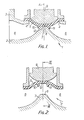
- the diaphragm valve 1 a portion of which is shown in the drawings, includes a valve body 2 having end connections 3, only one of which is shown in Figure 1 of the drawings.
- a diaphragm opening 4 is defined by the valve body, and a closure diaphragm 5 is secured in sealing engagement with the body to close the diaphragm opening 4.
- the diaphragm 5 and body 2 together define a flow passage 6 through the valve.
- a weir 7 formed by the valve body defines a seat 8 against which the closure diaphragm 5 can be pressed by a compressor 9 to close the valve to fluid flow.
- the closure diaphragm 5 includes a pair of tongues 10,11 which project into the flow passage adjacent the region 12 of the diaphragm which seals with the valve seat 8 when the diaphragm is in the closed position.
- the exact size and shape of the tongues is determined by the size and shape of the valve body and the required flow characteristics.
- the tongues are squat projections extending only a short distance either side of the longitudinal centre line of the valve. However, longer or shorter tongues may be used in certain applications.
- the tongues 10,11 are moulded integrally with the remainder of the diaphragm.
- the diaphragm will typically be moulded in the shape and configuration shown in Figure 2, in which case the position of the tongues on the diaphragm is chosen such that upon flexing of the diaphragm into the closed position shown in Figure 1 the tongues 10,11 flex away from each other and at the moment of contact with the weir 7 provide a slight interference with the edges of the weir.
- valve illustrated in the drawings includes two tongues symmetrically disposed on either side of the transverse central plane A of the valve and each symmetrical about the central longitudinal plane B of the valve, it may be desirable in some circumstances to have one or more tongues on one side of the transverse central plane A of the valve only, or to have more than one tongue on both sides of the transverse central plane A. Also, whilst the tongues 10,11 are aligned transversely to the direction C of fluid flow through the valve and extend only part of the way across the flow passage, other orientations may prove desirable in some circumstances.
- the primary function of the tongues is to improve the flow characteristics of the valve some improvement in the sealing of the valve may be obtained when the valve is fully closed since the tongue on the upstream side of the valve will tend to be pressed into sealing engagement with the weir by fluid pressure on that side of the valve. It may in some circumstances prove desirable to taper the tongues to provide the desired characteristics.
- valve incorporates a diaphragm which is an integral moulded structure, for example of rubber
- projections may be included on hard diaphragm facings such as are used in PTFE faced diaphragms.
- FIG. 6 there is shown a graphical representation of the results of tests comparing the flow characteristics of a valve fitted with a conventional diaphragm with the flow characteristics of a valve fitted with a diaphragm substantially as shown in Figures 1 to 5.
- the tests were carried out with a constant pressure drop of 5 cm. Hg. across the valve and Figure 6 shows flow rate F through the valve in Kg of water per second plotted against the number of turns T of the handwheel of the valve from fully closed (0 turns) to fully open (5 turns).
- Curve D shows the results for a conventional smooth diaphragm and it will be noted by comparing this curve with an ideal linear characteristic curve E that the conventional diaphragm produces highly non-linear flow rateso This renders a valve fitted with such a diaphragmunsuitable for use as a flow control valve.
- Curve G shows the results for the diaphragm substantially according to Figures 1 to 5. It will be noted that the flow rate F through the valve is slightly lower when the valve is fully open than the flow rate through the valve fitted with a conventional diaphragm. However, this reduced maximum flow rate is perfectly acceptable in most uses of the valve. It will be noted by comparing the curve G with the corresponding ideal linear characteristic curve E' that the valve fitted with the diaphragm according to the invention produces a much more linear variation in flow rates than that produced by the valve fitted with a conventional diaphragm. The curve G is sufficiently near to the ideal linear curve E' to render the valve suitable for use as a flow control valve in many applications.
- a steeper substantially linear characteristic curve can be obtained by replacing the tongues 10,11 with a plurality of tongues generally aligned with the direction of fluid flow through the valve.
- Each tongue 10,11 can, for example be replaced by five teeth-like tongues aligned perpendicular to the tongues 10,11 and each being generally triangular in both longitudinal and transverse cross-sections, i.e. as viewed in both Figures 1 and 3.
Landscapes
- Engineering & Computer Science (AREA)
- General Engineering & Computer Science (AREA)
- Mechanical Engineering (AREA)
- Lift Valve (AREA)
- Fluid-Driven Valves (AREA)
Applications Claiming Priority (2)
| Application Number | Priority Date | Filing Date | Title |
|---|---|---|---|
| GB7900805 | 1979-01-09 | ||
| GB7900805 | 1979-01-09 |
Publications (1)
| Publication Number | Publication Date |
|---|---|
| EP0013618A1 true EP0013618A1 (en) | 1980-07-23 |
Family
ID=10502413
Family Applications (1)
| Application Number | Title | Priority Date | Filing Date |
|---|---|---|---|
| EP80300072A Withdrawn EP0013618A1 (en) | 1979-01-09 | 1980-01-08 | Diaphragm valves |
Country Status (8)
| Country | Link |
|---|---|
| EP (1) | EP0013618A1 (da) |
| JP (1) | JPS55123056A (da) |
| AR (1) | AR220805A1 (da) |
| AU (1) | AU5449380A (da) |
| DK (1) | DK8580A (da) |
| ES (1) | ES487521A1 (da) |
| NO (1) | NO800040L (da) |
| ZA (1) | ZA80125B (da) |
Cited By (1)
| Publication number | Priority date | Publication date | Assignee | Title |
|---|---|---|---|---|
| CN104405920A (zh) * | 2014-09-19 | 2015-03-11 | 孙维 | 一种防漏隔膜阀 |
Citations (3)
| Publication number | Priority date | Publication date | Assignee | Title |
|---|---|---|---|---|
| CH316891A (de) * | 1953-09-11 | 1956-10-31 | Alpura Ag | Membranventil |
| GB898049A (en) * | 1959-06-24 | 1962-06-06 | Parfonry & Lielens Ets | Improvements to fluid flow control valves |
| FR2033931A5 (da) * | 1969-02-14 | 1970-12-04 | Clouth Gummiwerke Ag |
-
1980
- 1980-01-08 ES ES487521A patent/ES487521A1/es not_active Expired
- 1980-01-08 NO NO800040A patent/NO800040L/no unknown
- 1980-01-08 AR AR279569A patent/AR220805A1/es active
- 1980-01-08 DK DK8580A patent/DK8580A/da unknown
- 1980-01-08 EP EP80300072A patent/EP0013618A1/en not_active Withdrawn
- 1980-01-09 ZA ZA00800125A patent/ZA80125B/xx unknown
- 1980-01-09 JP JP61180A patent/JPS55123056A/ja active Pending
- 1980-01-09 AU AU54493/80A patent/AU5449380A/en not_active Abandoned
Patent Citations (3)
| Publication number | Priority date | Publication date | Assignee | Title |
|---|---|---|---|---|
| CH316891A (de) * | 1953-09-11 | 1956-10-31 | Alpura Ag | Membranventil |
| GB898049A (en) * | 1959-06-24 | 1962-06-06 | Parfonry & Lielens Ets | Improvements to fluid flow control valves |
| FR2033931A5 (da) * | 1969-02-14 | 1970-12-04 | Clouth Gummiwerke Ag |
Cited By (1)
| Publication number | Priority date | Publication date | Assignee | Title |
|---|---|---|---|---|
| CN104405920A (zh) * | 2014-09-19 | 2015-03-11 | 孙维 | 一种防漏隔膜阀 |
Also Published As
| Publication number | Publication date |
|---|---|
| ES487521A1 (es) | 1980-10-01 |
| NO800040L (no) | 1980-07-10 |
| JPS55123056A (en) | 1980-09-22 |
| ZA80125B (en) | 1980-12-31 |
| AU5449380A (en) | 1980-07-17 |
| AR220805A1 (es) | 1980-11-28 |
| DK8580A (da) | 1980-07-10 |
Similar Documents
| Publication | Publication Date | Title |
|---|---|---|
| US4054152A (en) | Check valve | |
| US4730635A (en) | Valve and method | |
| EP0452045B1 (en) | Normally closed duckbill valve assembly | |
| US3882891A (en) | Check valve | |
| US5090450A (en) | Plug valve | |
| EP0434598A1 (en) | Diaphragm control valve | |
| DE69523618D1 (de) | Intravenöses verbindungsstück mit ventil für fluidleitung | |
| GB1093711A (en) | Fluid controlling valves | |
| CN1142029A (zh) | 平板阀 | |
| CN107202171B (zh) | 一种自调压型智能调节阀 | |
| CA2540633A1 (en) | Valve assembly | |
| US3741234A (en) | Valve | |
| US3631882A (en) | Diaphragm valve | |
| USRE27399E (en) | Nonreturn valves | |
| US6394135B2 (en) | Balanced plug valve with contour wall | |
| CA1285545C (en) | Valve with improved seal | |
| KR850001584B1 (ko) | 복식 차단밸브 장치 | |
| GB2040407A (en) | Diaphragm valves | |
| EP0013618A1 (en) | Diaphragm valves | |
| US3310280A (en) | Diaphragm valve | |
| CA2331171A1 (en) | Electromagnetic valve for gaseous fluids | |
| US3556138A (en) | Nonreturn valves | |
| JPH05231553A (ja) | 流量調節装置 | |
| US5167397A (en) | Diaphragm valve with mechanically linked diaphragm | |
| EP0091164B1 (en) | Device passing a pressurized medium e.g. an adjustable flow rate limiter, a return valve or a flow rate meter |
Legal Events
| Date | Code | Title | Description |
|---|---|---|---|
| PUAI | Public reference made under article 153(3) epc to a published international application that has entered the european phase |
Free format text: ORIGINAL CODE: 0009012 |
|
| AK | Designated contracting states |
Designated state(s): AT BE CH DE FR IT NL SE |
|
| 17P | Request for examination filed |
Effective date: 19801222 |
|
| STAA | Information on the status of an ep patent application or granted ep patent |
Free format text: STATUS: THE APPLICATION IS DEEMED TO BE WITHDRAWN |
|
| 18D | Application deemed to be withdrawn |
Effective date: 19821116 |
|
| RIN1 | Information on inventor provided before grant (corrected) |
Inventor name: TRIMBLE, MAURICE WILSON |