EP0013075B1 - Transfer membrane apparatus - Google Patents
Transfer membrane apparatus Download PDFInfo
- Publication number
- EP0013075B1 EP0013075B1 EP79302652A EP79302652A EP0013075B1 EP 0013075 B1 EP0013075 B1 EP 0013075B1 EP 79302652 A EP79302652 A EP 79302652A EP 79302652 A EP79302652 A EP 79302652A EP 0013075 B1 EP0013075 B1 EP 0013075B1
- Authority
- EP
- European Patent Office
- Prior art keywords
- conduit
- furrows
- flow
- fluid
- conduits
- Prior art date
- Legal status (The legal status is an assumption and is not a legal conclusion. Google has not performed a legal analysis and makes no representation as to the accuracy of the status listed.)
- Expired
Links
Images
Classifications
-
- B—PERFORMING OPERATIONS; TRANSPORTING
- B01—PHYSICAL OR CHEMICAL PROCESSES OR APPARATUS IN GENERAL
- B01D—SEPARATION
- B01D63/00—Apparatus in general for separation processes using semi-permeable membranes
- B01D63/08—Flat membrane modules
- B01D63/082—Flat membrane modules comprising a stack of flat membranes
- B01D63/084—Flat membrane modules comprising a stack of flat membranes at least one flow duct intersecting the membranes
- B01D63/085—Flat membrane modules comprising a stack of flat membranes at least one flow duct intersecting the membranes specially adapted for two fluids in mass exchange flow
-
- B—PERFORMING OPERATIONS; TRANSPORTING
- B01—PHYSICAL OR CHEMICAL PROCESSES OR APPARATUS IN GENERAL
- B01D—SEPARATION
- B01D2313/00—Details relating to membrane modules or apparatus
- B01D2313/08—Flow guidance means within the module or the apparatus
-
- B—PERFORMING OPERATIONS; TRANSPORTING
- B01—PHYSICAL OR CHEMICAL PROCESSES OR APPARATUS IN GENERAL
- B01D—SEPARATION
- B01D2313/00—Details relating to membrane modules or apparatus
- B01D2313/24—Specific pressurizing or depressurizing means
- B01D2313/243—Pumps
-
- Y—GENERAL TAGGING OF NEW TECHNOLOGICAL DEVELOPMENTS; GENERAL TAGGING OF CROSS-SECTIONAL TECHNOLOGIES SPANNING OVER SEVERAL SECTIONS OF THE IPC; TECHNICAL SUBJECTS COVERED BY FORMER USPC CROSS-REFERENCE ART COLLECTIONS [XRACs] AND DIGESTS
- Y10—TECHNICAL SUBJECTS COVERED BY FORMER USPC
- Y10S—TECHNICAL SUBJECTS COVERED BY FORMER USPC CROSS-REFERENCE ART COLLECTIONS [XRACs] AND DIGESTS
- Y10S128/00—Surgery
- Y10S128/03—Heart-lung
-
- Y—GENERAL TAGGING OF NEW TECHNOLOGICAL DEVELOPMENTS; GENERAL TAGGING OF CROSS-SECTIONAL TECHNOLOGIES SPANNING OVER SEVERAL SECTIONS OF THE IPC; TECHNICAL SUBJECTS COVERED BY FORMER USPC CROSS-REFERENCE ART COLLECTIONS [XRACs] AND DIGESTS
- Y10—TECHNICAL SUBJECTS COVERED BY FORMER USPC
- Y10S—TECHNICAL SUBJECTS COVERED BY FORMER USPC CROSS-REFERENCE ART COLLECTIONS [XRACs] AND DIGESTS
- Y10S261/00—Gas and liquid contact apparatus
- Y10S261/28—Blood oxygenators
Definitions
- the invention is concerned with apparatus for effecting transfer of heat or mass between two fluids, of which at least one is usually a liquid, through a transfer membrane.
- apparatus for ultrafiltration/reverse osmosis applications and in the medical field, for example, in blood oxygenators, that is artificial lungs, and dialysers, such as artificial kidneys, in which case one fluid is blood, and the other is oxygen or dialysate.
- blood oxygenators that is artificial lungs
- dialysers such as artificial kidneys
- one fluid is blood
- the other is oxygen or dialysate.
- the efficiency of the transfer across the membrane is limited by the extent to which the total volume of fluid can be brought into close proximity with the membrane.
- the conduit may be defined between two predominantly planar surfaces, so that it has an elongate cross-section transverse to the general direction of mean flow through the conduit, at least one of the surfaces then being provided by the membrane in which the requisite hollows are provided by parallel furrows.
- the problem is particularly significant in ultrafiltration/reverse osmosis devices, such as those used for concentrating dyes or proteins, for recovering electrolytic paint solvents, or in the desalination of sea water.
- ultrafiltration/reverse osmosis devices such as those used for concentrating dyes or proteins, for recovering electrolytic paint solvents, or in the desalination of sea water.
- the performance of all these devices are limited by concentration polarisation of the membrane surface.
- the particle flow path will be generally zig-zag through the conduit and the concentration gradient along the conduit will remain substantially unchanged by the pulsations.
- the transverse reciprocatory flow component does not require flow reversal in the mean flow direction so that the apparatus will operate satisfactorily with comparatively small peak to peak pressure differentials in the transverse direction.
- the first pumping means which provides the mean flow along the conduit, may be a unidirectional pump such as a roller pump.
- the second pumping means which provides the transverse reciprocatory flow component may comprise a flexible bladder along each side each of the conduit, the two bladders being activated in turn, for example by mechanically linked actuators, to apply pressure alternately to the opposite edges of the conduit.
- the bladders are preferably sub-divided in the longitudinal direction of the conduit so that each part of the bladder pumps back fluid into only an adjacent part of the conduit.
- the furrows may extend substantially parallel to the longitudinal direction of the conduit, or alternatively they may extend obliquely, for example at substantially 45°, to the longitudinal direction of the conduit.
- the second fluid with which transfer is to be effected through the membrane will pass with a mean flow in counter or cross current to the first fluid on the opposite side of the or each membrane wall of the first conduit.
- a second conduit for the second fluid also defined between two predominantly planar surfaces of which one is provided by the membrane so that the two conduits are separated by a common wall formed by the membrane; at least one of the predominantly planar surfaces defining the second conduit being formed with alternate furrows and ridges; and third pumping means being provided for passing the second fluid through the second conduit in a flow having a pulsatile component transverse to the furrows in the second conduit, the arrangement being such that pulsation of the second fluid past the furrows in the second conduit gives rise in those furrows to a rotary fluid flow having components of motion parallel and perpendicular to the pulsatile flow component in the second conduit and to the membrane.
- the pulsatile flow of the second fluid may involve a reciprocatory flow component superimposed in the same direction as or transverse to a mean flow of the second fluid which in turn may be in counter or cross current to the mean flow of the first liquid.
- the furrows in the second conduit are parallel to those in the first conduit.
- the furrows in the second conduit may then be in the adjacent face of the common membrane wall, for example by making the membrane wall symmetrically undulating.
- the predominantly planar surface defining the wall of the second conduit remote from the first conduit is provided with the alternate furrows and ridges.
- the pulsatile flow produced by the third pumping means to comprise a mean flow of the second fluid along the second conduit in counter current to the mean flow of the first fluid along the first conduit, and a superimposed reciprocatory flow component transversely to the direction of mean flow.
- Both walls of the first conduit, separating the first conduit from the two second conduits, will then be formed by transfer membranes.
- the two predominantly planar surfaces, between which at least one of the conduits is defined may be separated along the ridges between the furrows by discontinuous webs, openings in which provide communication between adjacent furrows and allow the fluid to pass from one furrow to the next as jets. These jets assist in setting up eddies in the furrows into which they are discharged.
- the reciprocatory pulsatile flow components of the two fluids in the two conduits may be in phase and in the same direction, thereby minimising undesirable reverse ultrafiltration effects.
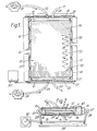
- the illustrated dialyser comprises a rectangular housing 10 providing an internal generally rectangular shallow chamber 11. Located within the chamber and supported by its close proximity to the walls of the chamber, is a membrane envelope assembly 12. As will become apparent from a subsequent description of Figures 3 and 4, the membrane envelope assembly includes four superimposed membrane layers of which the upper and lower membranes 13 are impermeable and the inner two membranes 14 semi-permeable. Adjacent membranes are sealed together along the ends of the assembly, and are sealed, along the side edges of the assembly to respective dividing walls 15 of a respective one of two flexible bladders 16 extending along the side edges of the housing 10. The membrane assembly thus provides three superposed conduits each defined between two predominantly planar surfaces so that each conduit has an elongate cross-section transverse to its length. The upper and lower conduits 17, between adjacent membranes 13 and 14, are intended for dialysate and the central conduit 18, between the membranes 14, is intended for blood.
- Each conduit is provided at one end with a manifold portion 19 and at the other end with a manifold portion 20, the manifold portions of the adjacent conduits being sealed from one another by the membranes.
- These manifolds are coupled with a system for circulation of blood and dialysate through the conduits.
- blood is pumped into the manifold portion 19 at the end of the blood conduit 18 by a roller pump 21 through a blood inlet duct 22. After passing along the conduit 18 the blood is discharged from the manifold portion 20 of the blood conduit through a blood outlet duct 23.
- dialysate is caused to flow, in counter current to the blood, through the two dialysate conduits 17.
- a roller pump 24 which pumps dialysate through a branched dialysate inlet duct 25 into the two manifold portions 20 at the adjacent ends of the dialysate conduits 17.
- the dialysate is discharged from the manifold portions 19 at the downstream ends of the conduits 17 into a common dialysate discharge duct 26.
- the ducts 22, 23, 25 and 26 may be made of a thermoplastics material and heat sealed to thermoplastic material from which the membranes are made.
- more complex distribution arrangements may be provided, such as distributors within the manifold portions clamped between parts of the housing and in alignment with ports in the housing.
- both liquids are also subjected to a superimposed reciprocatory flow component to and fro across the respective conduit.
- This is achieved by subjecting the flexible bladders alternately to pressure by means of rollers 27 which are mounted on arms 28 pivoted on a common base 29 and rocked to and fro in synchronism by means of a crank drive 30 and connecting rod 31.
- the blood and dialysate will thus repeatedly be forced from their respective conduits into the corresponding chambers between the separating walls 15 as one bladder 16 is allowed to expand, and subsequently expelled from that bladder as the corresponding roller 27 depresses the bladder.
- each bladder 16 is divided by indentations 33 into separate longitudinal sections so that blood or dialysate received within a part of the bladder, will be expelled from substantially the same part of the bladder and no short circuit path would exist between the manifold portions 19 and 20 along the bladders.
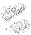
- Each of the membranes 13 and 14 is shaped to provide a series of parallel furrows 34 separated by ridges 35. Each furrow 34 is approximately 3 mm wide and between 1 and 1.5 mm deep. The separation of the adjacent pairs of membranes 13 and 14 and the minimum separation of the membranes 14 at the ridges 35 are each substantially 0.5 mm. The spaces corresponding to the furrows 34 in the conduits 17 are separated by discontinuous spacer webs 36 in which rectangular slots 37, each 0.5 mm deep and 0.5 mm wide, are spaced at 1 mm intervals along the webs. Similar webs could be provided in the conduit 18.
- the membranes 13 and 14 are provided with their furrowed shape by being assembled flat and appropriately sealed together and placed between furrowed plates.
- the conduits are pumped full of water which causes the plastics material from which the membranes are made to yield plastically beyond their elastic limit and adopt permanently the final shape.
- the furrows may extend at substantially 45° to the longitudinal and transverse directions of the conduit, or, as suggested at 39 parallel to the length of the conduit. These angles are not necessary alternatives but merely exemplary. What is important is that the blood and dialysate flow along their respective conduits with a composite pulsatile flow, the flow velocity continually changes in a direction across the ridges and furrows. As a result vortexes VB are formed in the furrows 34 in the blood conduit 18 and vortexes VD are formed in the furrows 34 in the dialysate conduits 17. In general these vortexes will have a helical component owing to the inclination of the furrows to the direction of instantaneous flow through the conduits.
- the vortexes are enhanced in the dialysate conduits 17 by the openings 37 through which jets of the dialysate pass and are deflected by the solid portions of the webs 36 at the next ridge 35.
- the vortexes promote good mixing of the blood in the blood conduit and of the dialysate in the dialysate conduits and hence improved contact between the respective liquid and the transfer membranes 14.
- a non-dimensional peak Reynold's number relating to the fluid flow exceeds five and in practice may be as high as fifty.
- the peak Reynold's number is defined as where
- the invention has been specifically described with relation to an artificial kidney, in which the transfer membranes 14 are capable of passing selected molecules, the invention is equally applicable to heat transfer systems. In the latter case the transfer membranes will usually be made of a suitable metal.
Landscapes
- Chemical & Material Sciences (AREA)
- Chemical Kinetics & Catalysis (AREA)
- External Artificial Organs (AREA)
- Separation Using Semi-Permeable Membranes (AREA)
- Heat-Exchange Devices With Radiators And Conduit Assemblies (AREA)
Applications Claiming Priority (2)
| Application Number | Priority Date | Filing Date | Title |
|---|---|---|---|
| GB7845576 | 1978-11-22 | ||
| GB4557678 | 1978-11-22 |
Publications (2)
| Publication Number | Publication Date |
|---|---|
| EP0013075A1 EP0013075A1 (en) | 1980-07-09 |
| EP0013075B1 true EP0013075B1 (en) | 1984-05-09 |
Family
ID=10501222
Family Applications (1)
| Application Number | Title | Priority Date | Filing Date |
|---|---|---|---|
| EP79302652A Expired EP0013075B1 (en) | 1978-11-22 | 1979-11-21 | Transfer membrane apparatus |
Country Status (11)
| Country | Link |
|---|---|
| US (1) | US4328102A (OSRAM) |
| EP (1) | EP0013075B1 (OSRAM) |
| JP (1) | JPH0122802B2 (OSRAM) |
| AU (1) | AU531732B2 (OSRAM) |
| BE (1) | BE880183A (OSRAM) |
| CA (1) | CA1136057A (OSRAM) |
| DE (1) | DE2966971D1 (OSRAM) |
| DK (1) | DK281880A (OSRAM) |
| GB (1) | GB2048713B (OSRAM) |
| WO (1) | WO1980001043A1 (OSRAM) |
| ZA (1) | ZA796243B (OSRAM) |
Cited By (1)
| Publication number | Priority date | Publication date | Assignee | Title |
|---|---|---|---|---|
| DE102008019829A1 (de) | 2008-04-19 | 2009-10-22 | Solarnext Ag | Einrichtung zum Massentransport zwischen zwei Fluida durch eine Membran |
Families Citing this family (28)
| Publication number | Priority date | Publication date | Assignee | Title |
|---|---|---|---|---|
| JPS57209604A (en) * | 1981-06-19 | 1982-12-23 | Daicel Chem Ind Ltd | Separator element of membrane |
| US4735726A (en) * | 1981-07-22 | 1988-04-05 | E. I. Du Pont De Nemours And Company | Plasmapheresis by reciprocatory pulsatile filtration |
| US4639317A (en) * | 1982-02-16 | 1987-01-27 | E. I. Du Pont De Nemours And Company | Plasmapheresis filtration module having improved sealing means |
| US4636312A (en) * | 1982-02-16 | 1987-01-13 | E. I. Du Pont De Nemours And Company | Plasmapheresis filtration module having improved end plate |
| US4640776A (en) * | 1982-02-16 | 1987-02-03 | E. I. Du Pont De Nemours And Company | Plasmapheresis filtration module having pressure balancing and sealing means |
| US4769150A (en) * | 1982-02-16 | 1988-09-06 | E. I. Du Pont De Nemours And Company | Method and apparatus for plasmapheresis by reciprocatory pulsatile filtration |
| US4661458A (en) * | 1983-08-31 | 1987-04-28 | Cell Environmental Systems, Ltd. | Cell culture system |
| CH670573A5 (OSRAM) * | 1985-11-22 | 1989-06-30 | Sulzer Ag | |
| US4756835A (en) * | 1986-08-29 | 1988-07-12 | Advanced Polymer Technology, Inc. | Permeable membranes having high flux-density and low fouling-propensity |
| US5244930A (en) * | 1991-12-13 | 1993-09-14 | Brigham And Women's Hospital | Biphasic foam blood mass transfer device |
| US5429184A (en) * | 1994-03-28 | 1995-07-04 | Minntech Corporation | Wound heat exchanger oxygenator |
| US5626759A (en) * | 1994-08-01 | 1997-05-06 | Regents Of The University Of Colorado | Blood treatment device with moving membrane |
| US5634892A (en) * | 1995-02-23 | 1997-06-03 | Whalen; Robert L. | Extracorporeal membrane oxygenator |
| EP1423338B1 (en) * | 2000-03-08 | 2007-01-24 | Zenon Technology Partnership | Reaktor with membrane module for gas transfer and membrane supported biofilm process |
| US7294259B2 (en) | 2003-02-13 | 2007-11-13 | Zenon Technology Partnership | Membrane module for gas transfer |
| US7175763B2 (en) * | 2003-02-13 | 2007-02-13 | Zenon Technology Partnership | Membrane supported biofilm process for autotrophic reduction |
| US7118672B2 (en) * | 2003-02-13 | 2006-10-10 | Zenon Technology Partnership | Membrane supported bioreactor for municipal and industrial wastewater treatment |
| WO2004071973A1 (en) * | 2003-02-13 | 2004-08-26 | Zenon Environmental Inc. | Supported biofilm apparatus and process |
| US7300571B2 (en) * | 2003-02-13 | 2007-11-27 | Zenon Technology Partnership | Supported biofilm apparatus |
| US7303676B2 (en) * | 2003-02-13 | 2007-12-04 | Zenon Technology Partnership | Supported biofilm apparatus and process |
| DE102005011471B4 (de) * | 2005-03-12 | 2008-04-10 | Melin, Thomas, Prof.Dr.-Ing. | Membranvorrichtung und Verfahren zur Herstellung einer Membranvorrichtung |
| DK2162402T3 (da) | 2007-04-20 | 2020-09-07 | Zenon Tech Partnership | Membranbåret biofilmanordning og fremgangsmåde |
| EP2060314A4 (en) * | 2007-07-03 | 2012-07-04 | Sumitomo Elec Fine Polymer Inc | FLATMEMBRANE FILTRATION ELEMENT AND FLATMEMBRANE FILTRATION MODULE |
| DE102008019828A1 (de) | 2008-04-19 | 2009-10-29 | Solarnext Ag | Folienwärmetauscher |
| US8545754B2 (en) | 2009-04-23 | 2013-10-01 | Medtronic, Inc. | Radial design oxygenator with heat exchanger |
| GB201108495D0 (en) | 2011-05-20 | 2011-07-06 | Haemair Ltd | Gas/fluid exchange apparatus |
| CN105008027A (zh) | 2013-02-22 | 2015-10-28 | 通用电气公司 | 用于支承生物膜的膜片组件 |
| CN107018659A (zh) | 2014-03-20 | 2017-08-04 | 通用电气公司 | 具有初级处理和mbr或mabr‑ifas反应器的废水处理 |
Family Cites Families (18)
| Publication number | Priority date | Publication date | Assignee | Title |
|---|---|---|---|---|
| GB935431A (en) * | 1958-05-29 | 1963-08-28 | Nat Res Dev | Improvements in apparatus for the treatment of multi-phase systems |
| US3332746A (en) * | 1963-03-29 | 1967-07-25 | Single Cell Res Foundation Inc | Pulsatile membrane oxygenator apparatus |
| GB1160433A (en) * | 1966-05-24 | 1969-08-06 | Bell S Medical Products Ltd | Improvements in or relating to Valveless Pumps. |
| UST867005I4 (en) | 1968-09-30 | 1969-10-21 | Artificial dialyzing body organ | |
| FR1593273A (OSRAM) * | 1968-11-20 | 1970-05-25 | ||
| US3567028A (en) * | 1968-12-26 | 1971-03-02 | Research Corp | Membrane envelope assembly |
| GB1368465A (en) * | 1971-03-30 | 1974-09-25 | Apv Co Ltd | Heat exchangers |
| FR2131144A5 (OSRAM) * | 1971-04-13 | 1972-11-10 | Rhone Poulenc Sa | |
| DE2134611A1 (de) * | 1971-07-10 | 1973-01-25 | Siegfried Klusch | Einrichtung zur steigerung der dialysance bei dialysatoren |
| GB1506555A (en) * | 1974-05-24 | 1978-04-05 | Johnson & Johnson | Blood reservoir |
| GB1505901A (en) * | 1974-05-24 | 1978-04-05 | Johnson & Johnson | Mass or heat transfer using disturbed flow to create convective vortices |
| FR2276856A1 (fr) * | 1974-07-05 | 1976-01-30 | Selegny Eric | Perfectionnements aux moyens pour le transfert d'un solute a travers une membrane separant deux fluides, dont au moins l'un est un liquide |
| US4037616A (en) * | 1975-06-27 | 1977-07-26 | Harry Pinkerton | Proportioning fluids |
| US4096059A (en) * | 1976-05-12 | 1978-06-20 | Pinkerton Harry E | Proportioning fluids |
| US4079007A (en) * | 1976-09-07 | 1978-03-14 | Union Carbide Corporation | Hemodialysis system with modular dialysate manifold assembly |
| GB1595058A (en) * | 1976-10-22 | 1981-08-05 | Bellhouse Brian John | Membrane blood oxygenators |
| JPS5450196A (en) * | 1977-09-28 | 1979-04-19 | Kato Isamu | Method of dialyzing blood in artificial kidney |
| FR2413930A1 (fr) * | 1978-01-04 | 1979-08-03 | Anvar | Procede et appareil d'agitation de fluide avec de faibles contraintes |
-
1979
- 1979-11-19 ZA ZA00796243A patent/ZA796243B/xx unknown
- 1979-11-20 CA CA000340177A patent/CA1136057A/en not_active Expired
- 1979-11-20 AU AU52973/79A patent/AU531732B2/en not_active Ceased
- 1979-11-21 BE BE0/198223A patent/BE880183A/fr not_active IP Right Cessation
- 1979-11-21 GB GB8015883A patent/GB2048713B/en not_active Expired
- 1979-11-21 WO PCT/GB1979/000200 patent/WO1980001043A1/en not_active Ceased
- 1979-11-21 EP EP79302652A patent/EP0013075B1/en not_active Expired
- 1979-11-21 DE DE7979302652T patent/DE2966971D1/de not_active Expired
- 1979-11-21 JP JP54501947A patent/JPH0122802B2/ja not_active Expired
-
1980
- 1980-06-12 US US06/206,545 patent/US4328102A/en not_active Expired - Lifetime
- 1980-06-30 DK DK2818/80A patent/DK281880A/da not_active Application Discontinuation
Cited By (1)
| Publication number | Priority date | Publication date | Assignee | Title |
|---|---|---|---|---|
| DE102008019829A1 (de) | 2008-04-19 | 2009-10-22 | Solarnext Ag | Einrichtung zum Massentransport zwischen zwei Fluida durch eine Membran |
Also Published As
| Publication number | Publication date |
|---|---|
| BE880183A (fr) | 1980-05-21 |
| AU5297379A (en) | 1980-05-29 |
| JPS55500973A (OSRAM) | 1980-11-20 |
| US4328102A (en) | 1982-05-04 |
| EP0013075A1 (en) | 1980-07-09 |
| AU531732B2 (en) | 1983-09-01 |
| DE2966971D1 (en) | 1984-06-14 |
| WO1980001043A1 (en) | 1980-05-29 |
| GB2048713B (en) | 1983-01-26 |
| JPH0122802B2 (OSRAM) | 1989-04-27 |
| CA1136057A (en) | 1982-11-23 |
| ZA796243B (en) | 1980-11-26 |
| GB2048713A (en) | 1980-12-17 |
| DK281880A (da) | 1980-06-30 |
Similar Documents
| Publication | Publication Date | Title |
|---|---|---|
| EP0013075B1 (en) | Transfer membrane apparatus | |
| US5254259A (en) | Method and apparatus for effecting the transfer of heat or mass through a membrane involving the use of vortices | |
| US4636309A (en) | Transfer membrane apparatus | |
| EP0020579B1 (en) | Transfer membrane apparatus | |
| US4110220A (en) | Mass transfer device | |
| US3396849A (en) | Membrane oxygenator-dialyzer | |
| US3695445A (en) | Pleated membrane transfer device | |
| US4222869A (en) | Dialyzing method of blood in artificial kidney | |
| US4312757A (en) | Methods and means for circulating a dialysate | |
| US4383921A (en) | Apparatus for heat or mass transfer | |
| EP0025435B1 (en) | Transfer membrane assembly | |
| US4636310A (en) | Transfer membrane apparatus | |
| US4636312A (en) | Plasmapheresis filtration module having improved end plate | |
| GB1592771A (en) | Apparatus for heat or mass transfer | |
| EP0387270B1 (en) | Transfer membrane apparatus | |
| GB1592772A (en) | Apparatus for heat or mass transfer | |
| JPH02172525A (ja) | 混合装置と混合方法 | |
| CA1252737A (en) | Plasmapheresis filtration module | |
| US4640776A (en) | Plasmapheresis filtration module having pressure balancing and sealing means | |
| CA1062113A (en) | Mass of heat transfer using disturbed flow to create convective vortices | |
| CA1069793A (en) | Mass or heat transfer using disturbed flow to create convective vortices | |
| EP0089434A2 (en) | Plasmapheresis filtration module | |
| SU1042753A1 (ru) | Массообменное устройство |
Legal Events
| Date | Code | Title | Description |
|---|---|---|---|
| PUAI | Public reference made under article 153(3) epc to a published international application that has entered the european phase |
Free format text: ORIGINAL CODE: 0009012 |
|
| AK | Designated contracting states |
Designated state(s): DE FR GB IT NL SE |
|
| 17P | Request for examination filed |
Effective date: 19801219 |
|
| ITF | It: translation for a ep patent filed | ||
| GRAA | (expected) grant |
Free format text: ORIGINAL CODE: 0009210 |
|
| AK | Designated contracting states |
Designated state(s): DE FR IT NL SE |
|
| REF | Corresponds to: |
Ref document number: 2966971 Country of ref document: DE Date of ref document: 19840614 |
|
| ET | Fr: translation filed | ||
| PGFP | Annual fee paid to national office [announced via postgrant information from national office to epo] |
Ref country code: FR Payment date: 19841030 Year of fee payment: 6 |
|
| PGFP | Annual fee paid to national office [announced via postgrant information from national office to epo] |
Ref country code: DE Payment date: 19841113 Year of fee payment: 6 |
|
| PGFP | Annual fee paid to national office [announced via postgrant information from national office to epo] |
Ref country code: SE Payment date: 19841231 Year of fee payment: 6 |
|
| PLBE | No opposition filed within time limit |
Free format text: ORIGINAL CODE: 0009261 |
|
| STAA | Information on the status of an ep patent application or granted ep patent |
Free format text: STATUS: NO OPPOSITION FILED WITHIN TIME LIMIT |
|
| 26N | No opposition filed | ||
| PGFP | Annual fee paid to national office [announced via postgrant information from national office to epo] |
Ref country code: NL Payment date: 19871130 Year of fee payment: 9 |
|
| PG25 | Lapsed in a contracting state [announced via postgrant information from national office to epo] |
Ref country code: SE Effective date: 19891122 |
|
| PG25 | Lapsed in a contracting state [announced via postgrant information from national office to epo] |
Ref country code: NL Effective date: 19900601 |
|
| NLV4 | Nl: lapsed or anulled due to non-payment of the annual fee | ||
| PG25 | Lapsed in a contracting state [announced via postgrant information from national office to epo] |
Ref country code: FR Effective date: 19900731 |
|
| PG25 | Lapsed in a contracting state [announced via postgrant information from national office to epo] |
Ref country code: DE Effective date: 19900801 |
|
| REG | Reference to a national code |
Ref country code: FR Ref legal event code: ST |
|
| EUG | Se: european patent has lapsed |
Ref document number: 79302652.7 Effective date: 19900705 |