EP0011284A2 - Uhr zur simultanen Anzeige verschiedener Weltzeiten - Google Patents
Uhr zur simultanen Anzeige verschiedener Weltzeiten Download PDFInfo
- Publication number
- EP0011284A2 EP0011284A2 EP79104482A EP79104482A EP0011284A2 EP 0011284 A2 EP0011284 A2 EP 0011284A2 EP 79104482 A EP79104482 A EP 79104482A EP 79104482 A EP79104482 A EP 79104482A EP 0011284 A2 EP0011284 A2 EP 0011284A2
- Authority
- EP
- European Patent Office
- Prior art keywords
- watch
- set forth
- cylinder
- electro
- casing
- Prior art date
- Legal status (The legal status is an assumption and is not a legal conclusion. Google has not performed a legal analysis and makes no representation as to the accuracy of the status listed.)
- Withdrawn
Links
Images


Classifications
-
- G—PHYSICS
- G04—HOROLOGY
- G04G—ELECTRONIC TIME-PIECES
- G04G9/00—Visual time or date indication means
- G04G9/0076—Visual time or date indication means in which the time in another time-zone or in another city can be displayed at will
Definitions
- This invention relates to a watch for displaying world time and more particularly to a watch for displaying multiple world times.
- Such watches can only give the time of one city in each operation and, thus, are functionally limited to only a few cities of the world.
- the invention as claimed is intended to provide a remedy by offering a convenient, small, light, portable world time device to display world time anywhere in the world.
- the invention provides a watch which is capable of a simultaneous display of a multiplicity of times for various zones of the world.
- the watch has a component which includes an endless surface means on which a plurality of longitudinally disposed rows of incremental time designations are provided to define a plurality of transversely disposed sets of predetermined time designations, a casing of flat rectangular box shape to house the endless surface means with at least one window to expose a transverse row of time designations to view and a means for moving the endless surface means relative to the window in increments equal to a center-line to center-line spacing between adjacent transverse rows.
- the endless surface means is in the form of an endless belt while the means for moving the belt includes a rotatable cylinder over which the belt is disposed and a knob secured to the cylinder and exposed to the outside of the casing for rotating the cylinder.
- a stop means is also provided for the cylinder in order to fix the position of the belt under the window of the casing.
- the stop means may include a toothed gear on the cylinder in meshing engagement with the belt, a stationary support in the casing, a cam slidably mounted on the support for fitting between two adjacent teeth of the gear and means, such as a spring for biasing the cam from the support to between two of the teeth to hold the gear and, thus, the cylinder in position.
- the endless surface means is in the form of a roller on which the incremental time designations are disposed.
- the means for moving this roller includes a knob which is secured to the roller and exposed to the outside of the casing for rotation of the roller.
- a stop means is also provided for holding the roller in the various incremental positions.
- the stop means is formed by a toothed gear which is formed on the roller, and a spring strip secured to the casing with a free end biased into engagement with the gear between two adjacent teeth of the gear. This strip may be cut out from the casing to be integral with the casing or may be a separate element.
- the casing has a pair of parallel windows with indicia adjacent each window to designate predetermined locations in different world time zones. In this way, the number of items which can be displayed can be multiplied. Additional windows can be also used or can be made wider with a corresponding increase in the number of indicia on the endless surface means.
- the watch is also provided with a read-out means, such as a digital or conventional analog (i.e. hand dial) read out, for indicating the actual time in hours, minutes and seconds.
- a read-out means such as a digital or conventional analog (i.e. hand dial) read out, for indicating the actual time in hours, minutes and seconds.
- the watch component may also be incorporated into a console constructed with a display board having a map divided into time zones with each time zone being coincident with a respective one of the longitudinal rows of time designations.
- the watch can be constructed to be manually actuated or automatically actuated.
- the endless surface means is in the form of an endless belt while the moving means is electronically operated.
- the moving or control means includes a main cylinder over which the belt is disposed, a cog wheel on the cylinder in meshing engagement with the belt and an electro-magnetic rotator assembly for rotating the cylinder in increments.
- the cylinder is provided with annular grooves of zig-zag shape while the rotator assembly includes a housing, a pair of electro-magnets disposed in the housing in spaced relation to each other, a permanent magnet disposed between the electro-magnets for reciprocating between two spaced terminal positions in response to selective activation of the electro-magnets and a driving pin which is mounted on the permanent magnet and projects into the groove of the cylinder.
- the permanent magnet moves from one terminal position to the other terminal position and causes rotation of the cylinder via the driving pin.
- the cylinder advances the belt one increment to display a different row of time designations.
- the activation of the electro-magnets occurs hourly so that the cylinder may be moved one increment per hour to display the next set of time designations.
- the electro-magnets can be actuated by a driving circuit which includes a polarity changing device for changing the direction of electric current flow from the device to the electro-magnets every hour automatically.
- a watch constructed in the above manner may be in the form of a digital quartz watch or an analog quartz watch.
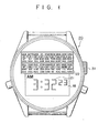
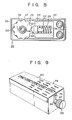
- the wrist watch 20 is of a digital type having a face 18 in which a digital read-out means 21 is disposed for indicating actual time in hours, minutes, and seconds.
- the watch 20 which is carried on a wrist band 19 has a component 22 for displaying multiple world times. This component 22 is adapted to illustrate the hour of various locations around the world coincident to the actual time displayed on the read-out means 21.
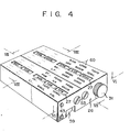
- the component for displaying the world times includes an endless surface means 23 in the form of an endless belt which is provided with a plurality of longitudinally disposed rows 24 of incremental time designations 25. These rows 24 also define a plurality of transversely disposed sets of predetermined time designations 25.
- the component 22 also has a casing 26 which houses the endless belt 23 and which has a pair of windows 27 to expose a transverse row of the time designations 25 to view.
- the component has means 28 for moving the belt 23 relative to the windows 27 in increments equal to a center-line to center-line spacing between the adjacent transverse rows of time designations 25.
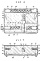
- This moving means includes a rotatable main cylinder 29, a pair of guide rollers 30 about which the belt 23 is disposed, and a knob 31 which is disposed outside the casing 26 and secured to the cylinder 29 via a shaft 32 for rotating the cylinder 29.
- the casing 26 has a flat rectangular box shape and is made of two components 33, 34 which fit into each other.
- the lower component 33 has a flat base 35 and four upstanding walls 36 while the top component 34 has a.flat top 37 and two depending side walls 38.
- the main cylinder 29 has a cylindrical body 39 with a hollow bore 40 in which a tubular sleeve 41 is fixedly mounted.
- a pair of trunnions 42 are located at the ends of the sleeve 41 and have suitable axles 43 by which the trunnions 42 are journalled in the side-walls 38 of the casing 26.
- one axle also serves as the shaft 32 of the knob 31.
- a tension spring 44 is located within the sleeve 41 between the trunnions 42 to bias the trunnions outwardly of each other. It is to be noted that the fit between the trunnions 42, sleeve 41 and body 39 is sufficient to permit rotation of the roller 29 via turning of the knob 31.
- Each roller 30 is constructed of a hollow tubular sleeve 45, a pair of trunnions "46 which are mounted at the ends of the sleeve 45 and carry axles 47 which are journalled in the walls 36, 38, and a tension spring 48 which is located within the sleeve 45 between the trunnions 46 to bias the trunnions 46 outwardly of each other.
- a tension spring 48 which is located within the sleeve 45 between the trunnions 46 to bias the trunnions 46 outwardly of each other.
- the watch component also includes stop means 49 for the roller 29.
- This stop means 49 includes a toothed gear 50 which is integrally formed on the cylinder 29 and disposed in meshing engagement with the belt 23 via suitable openings 51 in the belt 23.
- the stop means also has a stationary support or block 52 fixedly mounted within the casing 26 via pairs of screws 53, a cam 54 slidably mounted in the support 52 and a means in the form of a spring 55 biasing the cam 54 from the support 52 to between two gear teeth.
- the spring 55 is disposed in a recess 56 of the block 52 about a stem 57 of the cam 54 for stability purposes.
- the cam 54 has a conically shaped surface for fitting between the teeth of the gear 50.
- the block 52 has a pair of recesses 58 on opposite sides while the casing walls 36 are provided with cut-out plates 59 which are received in the recesses 58.
- the screws 53 serve to prevent forward and backward movement of the support 52 while the cut-outs 59 prevent ascending or decending movements.
- the teeth of the gear 50 are formed with a smooth streamline shape to facilitate movement of the gear 50 in relation to the cam 54. This will allow the turning of the knob 31 to be an effortless task.
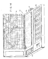
- the surface of the casing 26 is provided with indicia 60 adjacent each window 27 in order to designate predetermined locations in different world time zones.
- These indicia 60 are keyed to each other and to the designations 25 on the belt 23 so as to indicate various cities in the respective times zones.
- the indicia 60 are printed, for example,with dimensions of 0.80 millimeters or larger and in different colors to provide for ease of reading.and recognition.
- the indicia for A.M. times are made of a different color or shade than the P.M. times indicia so as to further indicate the time of day at a remote location of the world as well as a difference in days.
- the component 22 is provided with a designation of the International Date Line (IDL).
- IDL International Date Line
- the rows of time designations 25 on the belt 23 are disposed in 24 hour time cycles, i.e. 24 transverse rows and from, for example, 5 to 24 longitudinal rows across the belt depending upon the number of regions or time zones to be covered. For example, 5 time zones are illustrated in Fig. 4 and the time difference between the two windows 27 is a five hour difference.
- the position of the driving gear 50 is determined by the stop means 49,via the cam 54. Therefore, the belt 23 is so gauged that after each twist of the knoo J1, the desired time position will be visible through the windows 27. Thus, upon turning of the knob 31, the belt 23 is driven by the meshing of the gear 50 and the holes 51 in the belt 23. Each increment of motion of the belt moves the belt 23 exactly one hour increase or decrease.
- the correct time is first set on the read-out means 21. Thereafter, the knob 31 is turned to align the belt 23 to display the correct time for a known city at another point in the world in the appropriate position under a window 27. For example, if the read-out means 21 displays a time of 3:32 A.M. and the correct time in New York is 7:32 P.M., the knob 31 is turned until the designation "7P" appears in the window 27 under the designation NY. This simultaneously indicates the correct times in the other cities indicated on the timepiece. Subsequently, as the read-out 21 changes time to 4:00 A.M., the knob 31 is turned one increment either manually or automatically as described below.
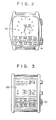
- the watch may also be constructed with a hand dial read-out as shown in Fig. 2 as well as in the form of a calendar watch with a day read-out 62 as shown in Fig. 3.
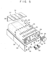
- the component for reading out world times may alternatively be constructed with an endless surface means in the form of a roller 63 on the surface of which the various time designations 25 are located in longitudinal and transverse rows.
- the casing 64 for housing the roller 63 is of generally box shape.
- the roller 63 is provided with means in the form of a knob 65 for rotating the cylinder 63 within the casing 64.
- the knob 65 is fixed to the roller 63 via a shaft 66 which is journalled within a cut-out 67 in the wall of the casing 64.
- the roller 63 has an enlarged collar 68 at the end adjacent to the knob 65 which rests on the floor of the casing 64 for smooth rotation thereon.
- the roller 63 also has a stop means in the form of a toothed gear 69 at the opposite end of the roller 63 and a spring strip 70 which is cut out from a side wall of the casing 64 in an integral manner.
- This strip 70 has a free end 71 which is biased into engagement with the gear 69 between two adjacent teeth thereon (see Fig. 11).
- the collar 68 is of a diameter to prevent the main surface of the cylinder 63 from rubbing on the surfaces of the casing 64 while the gear 69 serves to support the roller 63 on the casing bottom and the spring strip 70 serves to stabilize the roller 63.
- the lower part of the spring strip 70 is broader than the upper part to increase the durability of the strip 70.
- the surface of the rounded end 71 and the teeth of the gears 69 are made smooth and in streamline fashion in order to increase the ease by which the strip 70 may be able to slide when the gear 69 moves either forwards or backwards.
- the casing 64 also has a metal plate 72 mounted on the wall from which the spring strip 70 is cut out in order to reinforce the wall. This plate 72 is secured to the casing wall via bolts 73 as shown in Fig. ll.
- the top surface of the casing 64 is provided with a window 75 through which the indicia 25 on the roller 63 can be viewed.
- the watch can be provided with a component for displaying the world times of a further simplified construction.
- the casing of the display component 76 is of flat rectangular shape.
- an endless belt 23 is provided with the various indicia 25 and is disposed about two rollers 30, 30'.
- Each roller 30, 30' is constructed in the manner of the rollers described with respect to Fig. 6 . and one is provided with an extended axle 47 on which a knob 31 is mounted in the casing 76 in similar manner as described aboveand the casing 76 has the same construction as the casing 26.
- a stop means is not used but reliance is made upon the friction between the rollers 30, 30' and casing 76 to hold the belt 23 in position.
- the component can be incorporated into a pocket console unit 77 which contains a map display 78, a board display 79 indicating various cities within each time zone displayed on the map 78 and a window 80 for reading out the times in the various time zones 80.
- a knob 28 is used to rotate the endless surface means for displaying the various indicia 25 in a manner similar to that described above.
- the endless surface means may be in the form of a belt as described in Fig. 4 or in the form of a roller as described in Fig. 10.
- the console 77 may also be provided with a digital read-out 81 for displaying the time and data as well as with a calculator 82 for carrying out various mathematical computations.
- the map display 78 can be hinged to the console 77 to be closed down over the calculator 82 when not in use.
- the names of the cities arranged on the display 79 are positioned to provide easy access to locating the time of cities of interest.
- This console provides a traveller by air or sea with a rapid means of locating any location of the world and the time thereat.
- the watch may also be constructed as an automatic watch so that the world times are automatically incremented.
- the world time component 83 includes a casing 84 of flat rectangular shape in which a main cylinder 85 and a pair of guide rollers 86 are journalled via suitable axles 87, 88 in the side walls of the casing 84.
- the main cylinder 85 is constructed of a tubular sleeve 89 (Fig. 15) in which a pair of trunnions 90 are mounted and biased apart by means of a tension spring 91.
- the fit between the trunnions 90 and the sleeve 89 is such as to permit rotation of the sleeve 89.
- the roller 85 also has a cog wheel 92 on the outer periphery which serves to mesh with an endless belt 23 in a manner similar to the above.
- Each roller 86 is constructed in similar manner to the rollers 80 above and need not be further described.
- the casing 84 is provided with a window 27 as described abovewhile the endless belt 23 is provided with various time designations as described above.
- the moving means for moving the belt 23 is composed of a main cylinder 85, a cog wheel 92 on the cylinder which is disposed in meshing engagement with the belt 23, and an electro-magnetic rotator assembly 93 which rotates the cylinder 85 in increments, i.e. hourly increments.
- the cylinder 85 is provided with an annular groove 94 of zig-zag shape.
- the rotator assembly 93 includes a cylindrical housing 95 which is mounted within the casing 84 (see Fig. 15).
- the rotator assembly has a pair of electro-magnets 96 which are mounted at opposite ends of the housing 95 in spaced relation to each other to define a chamber, and a permanent magnet 97 which is disposed between the electro-magnets 96 for reciprocating between two spaced terminal positions within the chamber in response to selective activation of the electro-magnets 96.
- each electro-magnet 96 includes a soft iron core 100 which is disposed within the housing 95 and fixed to the casing 84 via a threaded screw 10L and a winding of coils 102 about each soft iron core 100.
- the soft iron cores 100 are converted into electro-magnets when electric currents flow through the coils 102.
- the coils 102 are installed to allow the electric current to flow in opposite directions.
- the electro-magnets 96 assume the same poles facing each other so that one pushes while the other pulls the permanent magnet 97 so as to move the permanent magnet 97 to one side or the other.
- the permanent magnet 97 is protected by a stainless steel case 103 and the driving pin 98 is welded or otherwise secured to this case 103.
- Suitable tabs 104 are disposed over the ends of the case 103 to minimize the impacts of the permanent magnet 97 against the electro-magnets 96.
- the shape of the groove 94 is such that the driving pin 98 cannot return to the same track but must move along in a new track thus turning the cylinder 85 in only one direction.
- the zig-zag tracks of the groove 94 are similar to the teeth of a gear.
- a case cap 105 is provided at one end close over the guide slot 99 while the opposite end is provided with a stop 106 which is in the form of a tap 106 extending into a slot in the casing 84.
- the watch is provided with a driving circuit 107 for activating the electro-magnets 96 each hour.
- This circuit 107 can be an ordinary quartz electronic circuit wherein current flows from a suitable energy source 108, for example a battery, through an oscillator 109 to a divider 110 to effect a display of seconds, minutes, and hours on a digital display 111.
- a manual switch control 112 is provided in the circuit to selectively deliver power through a buffer l13 and a driving circuit l14 to the electro-magnets 96 via lines 115, 116.
- the manual switch control 112 can be activated, for example by a push button.
- the driving circuit 114 contains a polarity changing device which is connected via the lines 115, 116 to the coils 102 of the electro-magnets 96, such that when the switch control 112 is activated, electric current passes to the coils 102 in one direction and is then programmed to flow in the reverse direction when the switch control 112 is activated the next time.
- the rotator assembly is capable of transferring motion directly even in a small space of, for example 0.50 millimeters. Moreover, the assembly eliminates the need for using multiple gears for changing speeds and transfering power.
- the buffer 113 and polarity changing device in the driving circuit 114 allow the direction of the electric current to be changed every hour automatically. It is to be noted that the activation of the polarity changing device need only occur each hour. At other times, no current is directed to the coils 102 of the electro-magnets 96.
- Fig. 18 illustrates a circuit 118 for an analog quartz watch wherein like reference characters indicate like parts as above.
- electric current flows through an oscillator 109 to a divider 110 and then to another divider 119 which enables current to flow once every hour.
- Power is transmitted from the oscillator 109 to suitable gears 120 to move second, minute, and hour hands 121 while a suitable crown 122 is used to adjust the read-out of the watch.
- the various windows of the watches may be formed of convex glass in order to enlarge the indicia of the time designations.
- the time figures may be printed in two different colors to distinguish between A.M. and P.M.
- the invention thus provides a watch which can be used automatically to display various times in various cities through the world simultaneously.
- the watch is of compact construction and can be easily used with a suitable wrist band as a wrist watch or with suitable chains or cases for use as a pocket watch, and the like.
Landscapes
- Physics & Mathematics (AREA)
- General Physics & Mathematics (AREA)
- Electric Clocks (AREA)
- Electromechanical Clocks (AREA)
Applications Claiming Priority (2)
| Application Number | Priority Date | Filing Date | Title |
|---|---|---|---|
| US05/959,670 US4307458A (en) | 1978-11-13 | 1978-11-13 | Watch for displaying multiple world times |
| US959670 | 1978-11-13 |
Publications (2)
| Publication Number | Publication Date |
|---|---|
| EP0011284A2 true EP0011284A2 (de) | 1980-05-28 |
| EP0011284A3 EP0011284A3 (de) | 1980-11-26 |
Family
ID=25502267
Family Applications (1)
| Application Number | Title | Priority Date | Filing Date |
|---|---|---|---|
| EP79104482A Withdrawn EP0011284A3 (de) | 1978-11-13 | 1979-11-13 | Uhr zur simultanen Anzeige verschiedener Weltzeiten |
Country Status (3)
| Country | Link |
|---|---|
| US (1) | US4307458A (de) |
| EP (1) | EP0011284A3 (de) |
| JP (1) | JPS5567679A (de) |
Families Citing this family (6)
| Publication number | Priority date | Publication date | Assignee | Title |
|---|---|---|---|---|
| US6006986A (en) * | 1997-10-28 | 1999-12-28 | Whalen; Edward E. | Global time calculator |
| FR2770914A1 (fr) * | 1997-11-07 | 1999-05-14 | Marcel Herve | Dispositif d'indication d'heures et minutes dans le monde |
| US20020175937A1 (en) * | 2001-05-24 | 2002-11-28 | Blakely Jason Yi | Multiple locale based display areas |
| US20030156497A1 (en) * | 2002-02-20 | 2003-08-21 | America America Ltda | World timepieces comprising different hour hands |
| US7941484B2 (en) | 2005-06-20 | 2011-05-10 | Symantec Operating Corporation | User interfaces for collaborative multi-locale context-aware systems management problem analysis |
| US7733743B2 (en) * | 2007-10-23 | 2010-06-08 | Boaz Baeksung Choi | Comprehensive time determining system |
Family Cites Families (6)
| Publication number | Priority date | Publication date | Assignee | Title |
|---|---|---|---|---|
| US2072457A (en) * | 1933-05-03 | 1937-03-02 | Ibm | Time indicating device |
| US2109535A (en) * | 1934-06-23 | 1938-03-01 | Jones John Thompson | Apparatus for displaying radio programs |
| US2417695A (en) * | 1946-06-08 | 1947-03-18 | James E Lewis | International time and day clock |
| US3232038A (en) * | 1964-03-23 | 1966-02-01 | World Time Corp | Clock apparatus |
| JPS49144267U (de) * | 1973-04-12 | 1974-12-12 | ||
| US4070822A (en) * | 1975-09-22 | 1978-01-31 | Copal Company Limited | Timer mechanism for use in a clock |
-
1978
- 1978-11-13 US US05/959,670 patent/US4307458A/en not_active Expired - Lifetime
-
1979
- 1979-08-09 JP JP10079979A patent/JPS5567679A/ja active Pending
- 1979-11-13 EP EP79104482A patent/EP0011284A3/de not_active Withdrawn
Also Published As
| Publication number | Publication date |
|---|---|
| JPS5567679A (en) | 1980-05-21 |
| US4307458A (en) | 1981-12-22 |
| EP0011284A3 (de) | 1980-11-26 |
Similar Documents
| Publication | Publication Date | Title |
|---|---|---|
| US3956879A (en) | Time indicating device | |
| HK101297A (en) | Timepiece calendar mechanism | |
| US20050180265A1 (en) | Clockwork and watch provided with such a clockwork | |
| US2192750A (en) | Clock time sundial | |
| US3695035A (en) | Timepiece movement | |
| US4307458A (en) | Watch for displaying multiple world times | |
| US6744695B2 (en) | Planisphere watch | |
| US6947351B1 (en) | Watch equipped with means for determining a location longitude | |
| US2001633A (en) | Geographical clock | |
| BR8900547A (pt) | Relogio | |
| US5349572A (en) | Clock dial | |
| US4953149A (en) | Two speed clock for daylight saving | |
| US4972392A (en) | Time conversion clock | |
| US3918251A (en) | Digital world clock | |
| US7154817B2 (en) | Electronic apparatus including an analogue display device for displaying any position on a dial | |
| US3379004A (en) | Tetra-time travel watch | |
| CH665326GA3 (de) | ||
| US4092823A (en) | Timepiece having display cylinders | |
| MY127604A (en) | Device displaying calendar date | |
| GB1513508A (en) | Reducing gear-train of an electronic watch with analogue display | |
| US4885729A (en) | Clock mechanism and display face | |
| US3226926A (en) | Geographical horological instrument | |
| ATE160030T1 (de) | Uhr mit mindestens einer durch die datumsanzeige getriebenen drehbaren anzeigevorrichtung | |
| CH679197GA3 (en) | Watch with geographical display - includes northern hemisphere display dial moving relative to sun position marker | |
| US2024066A (en) | Geographical clock |
Legal Events
| Date | Code | Title | Description |
|---|---|---|---|
| PUAI | Public reference made under article 153(3) epc to a published international application that has entered the european phase |
Free format text: ORIGINAL CODE: 0009012 |
|
| AK | Designated contracting states |
Designated state(s): CH DE FR GB NL |
|
| PUAL | Search report despatched |
Free format text: ORIGINAL CODE: 0009013 |
|
| AK | Designated contracting states |
Designated state(s): CH DE FR GB NL |
|
| 17P | Request for examination filed |
Effective date: 19810504 |
|
| STAA | Information on the status of an ep patent application or granted ep patent |
Free format text: STATUS: THE APPLICATION IS DEEMED TO BE WITHDRAWN |
|
| 18D | Application deemed to be withdrawn |
Effective date: 19830921 |
|
| RIN1 | Information on inventor provided before grant (corrected) |
Inventor name: LIN, OSCAR A. |