EP0010862B1 - Mit Lumineszenzdioden ausgerüstete Lichtquelleneinrichtung für einen Impulskodierer - Google Patents
Mit Lumineszenzdioden ausgerüstete Lichtquelleneinrichtung für einen Impulskodierer Download PDFInfo
- Publication number
- EP0010862B1 EP0010862B1 EP79302015A EP79302015A EP0010862B1 EP 0010862 B1 EP0010862 B1 EP 0010862B1 EP 79302015 A EP79302015 A EP 79302015A EP 79302015 A EP79302015 A EP 79302015A EP 0010862 B1 EP0010862 B1 EP 0010862B1
- Authority
- EP
- European Patent Office
- Prior art keywords
- led
- light
- pulse encoder
- source device
- light source
- Prior art date
- Legal status (The legal status is an assumption and is not a legal conclusion. Google has not performed a legal analysis and makes no representation as to the accuracy of the status listed.)
- Expired
Links
Images

Classifications
-
- H—ELECTRICITY
- H03—ELECTRONIC CIRCUITRY
- H03M—CODING; DECODING; CODE CONVERSION IN GENERAL
- H03M1/00—Analogue/digital conversion; Digital/analogue conversion
- H03M1/12—Analogue/digital converters
- H03M1/22—Analogue/digital converters pattern-reading type
- H03M1/24—Analogue/digital converters pattern-reading type using relatively movable reader and disc or strip
- H03M1/26—Analogue/digital converters pattern-reading type using relatively movable reader and disc or strip with weighted coding, i.e. the weight given to a digit depends on the position of the digit within the block or code word, e.g. there is a given radix and the weights are powers of this radix
Definitions
- This invention relates to an LED (Light Emitting Diode) light source device for a pulse encoder, in which the light emitted by first, second and third LED's passes through a movable pattern plate and a fixed pattern plate and is received by a plurality of photo cells, the fixed and movable pattern plates each having light transmitting and light interrupting areas and the photo cells being arranged in pairs such that each pair receives the light emitted by a respective one LED.
- LED Light Emitting Diode
- This LED light source device for a pulse encoder may be used, for example, for controlling a motor driving a table or a tool of machine tool.
- a rotary code plate 1 for a pulse encoder is schematically illustrated in Fig. 2.
- a sequence of light interrupting patterns "a” are formed by means of metal vapor deposition on the surface of the code plate 1, with a predetermined interval between the adjacent patterns.
- A. sequence of light interrupting patterns "f” are formed by means of metal vapor deposition on a fixed plate 3 located beneath the sequence of the light interrupting patterns "a”. The sequence of the light interrupting patterns "f” corresponds to the sequence of the light interrupting patterns "a”.
- LEDs 21, 22 and 23 are arranged against the patterns of the phases A, B and Z on the pattern plate 1 as illustrated in Fig. 1, at the positions 21, 22 and 23 illustrated in Fig. 2 by broken line circles.
- the light emitted by the LED 21 passes through a light transmitting portion between the light interrupting patterns "a" on the pattern plate 1, then, passes through a light transmitting portion between the light interrupting portions f on the fixed plate 3 and, finally, is received by photo cells 41 and 42.
- the light emitted by the LED at the position 21 above the pattern plate 1 and forwarded to the left-side portion of the pattern plate 1 is directed to the photo cell 41, while the light emitted by the LED at the position 21 above the pattern plate 1 and forwarded to the right-side portion of the pattern plate 1 is directed to the photo cell 42.
- the right-side photo cell 42 when the light signals are converted into electric signals by the photo cells 41 and 42, the right-side photo cell 42 produces an electric signal P which has a phase difference of 180° with regard to an electric signal P produced by the left-side photo cell 41.
- These electric signals P and P are applied to a differential amplifier which produces a desired output.
- this differential amplification system it is required that the amount of the left-side portion of the light emitted by the LEDs 21, 22 and 23, and directed to the photo cell 41, be the same as the amount of the right-side portion of the light emitted by the LEDs 21, 22 and 23, and directed to the photo cell 42.
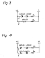
- the prior art circuit for supplying electric power to the LEDs is illustrated in Fig. 3.
- the LED 21, the LED 22 and a resistor R" connected in series in a branch k, are connected in parallel with the LED 23 and a resistor R 2 , connected in series in a branch I.
- the rates of variations of the currents i, and i 2 of the branches k and I are different.
- the difference of the rate of variation of the light between the LEDs 21 and 22 and the LED 23 exerts an undesirable influence on the output signal of this pulse encoder obtained by means of the differential amplification of the outputs P and P of the photo cells 41 and 42.
- an LED light source device for a pulse encoder, in which the light emitted by first, second and third LED's passes through a movable pattern plate and a fixed pattern plate and is received by a plurality of photo cells, the fixed and movable pattern plates each having light transmitting and light interrupting areas and the photo cells being arranged in pairs such that each pair receives the light emitted by a respective one LED, characterised in that the first and second LED's and a first resistor are connected in series across a voltage source to form a first branch circuit, and the third LED and a second resistor are connected in series with a dummy LED or dummy diode across the voltage source to form a second branch circuit in parallel with the first, whereby changes in the light characteristics of said first, second and third LED's are equalised.
- Fig. 4 illustrates an LED light source device for a pulse encoder in accordance with the present invention.
- a power supply circuit for an LED light source device for a pulse encoder is illustrated in Fig. 4.
- the structure of the pulse encoder with which light sources LED 21, LED 22, and LED 23 are associated is the same as the structure illustrated in Figs. 1 and 2.
- the LED 21, the LED 22 and the resistor R" connected in series in the branch k, are connected in parallel with the LED 23, a dummy Light Emitting Diode (DLED) and the resistor R 2' connected in series in a branch I'.
- the DLED is required to have the same voltage drop characteristic in the forward direction with reference to the value of the current and the temperature as each of the LEDs 21, 22 and 23 has. It is possible to use an ordinary diode in place of the Light Emitting Diode as the DLED.
Landscapes
- Engineering & Computer Science (AREA)
- Theoretical Computer Science (AREA)
- Optical Transform (AREA)
- Linear Or Angular Velocity Measurement And Their Indicating Devices (AREA)
Claims (1)
- LED-Lichtquellenanordnung für einen Pulscodierer, bei dem das von einer ersten, einer zweiten und einer dritten LED emittierte Licht eine bewegliche und eine feste Musterplatte durchläuft und von einer Vielzahl von Fotozellen aufgefangen wird, wobei die feste und die bewegliche Musterplatte je lichtdurchlässige und lichtundurchlässige Bereiche besitzen und die Fotozellen in Paaren so angeordnet sind, daß jedes Paar das von einer jeweiligen LED emittierte Licht empfängt, dadurch gekennzeichnet, daß die erste und die zweite LED (LED 21 und LED 22) und ein erster Widerstand (R,) in Reihe an eine Spannungsquelle (+E, 0) zur Bildung eines ersten Zweigkreises (k) angeschlossen sind und daß die dritte LED (23) und ein zweiter Widerstand (R2) in Reihe mit einer Blind-LED (DLED) oder einer Blinddiode an die Spannungsquelle zur Bildung eines zweiten Zweigkreises (1') parallel zum ersten angeschlossen sind, wobei Änderungen der Lichtcharakteristika der ersten, der zweiten und der dritten Leuchtdiode egalisiert sind.
Applications Claiming Priority (2)
| Application Number | Priority Date | Filing Date | Title |
|---|---|---|---|
| JP12273078A JPS5550117A (en) | 1978-10-06 | 1978-10-06 | Led light source device for pulse encoder |
| JP122730/78 | 1978-10-06 |
Publications (2)
| Publication Number | Publication Date |
|---|---|
| EP0010862A1 EP0010862A1 (de) | 1980-05-14 |
| EP0010862B1 true EP0010862B1 (de) | 1982-12-15 |
Family
ID=14843157
Family Applications (1)
| Application Number | Title | Priority Date | Filing Date |
|---|---|---|---|
| EP79302015A Expired EP0010862B1 (de) | 1978-10-06 | 1979-09-27 | Mit Lumineszenzdioden ausgerüstete Lichtquelleneinrichtung für einen Impulskodierer |
Country Status (4)
| Country | Link |
|---|---|
| US (1) | US4313058A (de) |
| EP (1) | EP0010862B1 (de) |
| JP (1) | JPS5550117A (de) |
| DE (1) | DE2964295D1 (de) |
Families Citing this family (9)
| Publication number | Priority date | Publication date | Assignee | Title |
|---|---|---|---|---|
| JPS59131115A (ja) * | 1983-01-14 | 1984-07-27 | Fanuc Ltd | 光学的エンコ−ダの駆動回路 |
| IT1160210B (it) * | 1983-09-30 | 1987-03-04 | Olivetti & Co Spa | Trasduttore ottico per rilevare la posizione di un organo mobile rispetto ad una struttura fissa |
| DE3507476A1 (de) * | 1985-03-02 | 1986-09-04 | Telefunken Electronic Gmbh | Optoelektronisches bauelement |
| DE3633939A1 (de) * | 1986-10-04 | 1988-04-14 | Heraeus Gmbh W C | Uebertragung von signalen aus einer sensoreinheit |
| US5150016A (en) * | 1990-09-21 | 1992-09-22 | Rohm Co., Ltd. | LED light source with easily adjustable luminous energy |
| US7465810B2 (en) * | 2004-10-25 | 2008-12-16 | Anaspec, Inc. | Reactive 1,3′-crosslinked carbocyanine |
| US8890045B2 (en) * | 2012-03-01 | 2014-11-18 | Avago Technologies General Ip (Singapore) Pte. Ltd. | Optical encoder with a current regulating circuit for a light emitter |
| EP2647966B2 (de) * | 2012-04-04 | 2017-08-23 | Siemens Aktiengesellschaft | Messwertgeber zum Erhalt einer Positionsinformation und Verfahren zu dessen Betrieb |
| US20220140217A1 (en) * | 2020-10-30 | 2022-05-05 | Raysolve Optoelectronics (Suzhou) Company Limited | Light emitting diode structure and method for manufacturing the same |
Family Cites Families (6)
| Publication number | Priority date | Publication date | Assignee | Title |
|---|---|---|---|---|
| DE2416113C2 (de) * | 1974-04-03 | 1984-09-27 | Quick-Rotan Becker & Notz Kg, 6100 Darmstadt | Istwertgeber für drehzahlgeregelte Antriebe |
| US3997782A (en) * | 1974-09-06 | 1976-12-14 | Dynapar Corporation | Rotary pulse transducer having stator sealing means |
| US3995156A (en) * | 1975-03-25 | 1976-11-30 | Quick-Rotan Becker & Notz Kg | Transmitter for governed-speed drives employing an optical grating and photocells at an angle thereto |
| US4063227A (en) * | 1975-09-08 | 1977-12-13 | Cega, Inc. | Smoke detector |
| US4110611A (en) * | 1975-12-17 | 1978-08-29 | Candid Logic, Inc. | Optical position transducer |
| US4179629A (en) * | 1977-08-10 | 1979-12-18 | Westinghouse Electric Corp. | Failsafe logic function apparatus |
-
1978
- 1978-10-06 JP JP12273078A patent/JPS5550117A/ja active Pending
-
1979
- 1979-09-27 US US06/079,480 patent/US4313058A/en not_active Expired - Lifetime
- 1979-09-27 DE DE7979302015T patent/DE2964295D1/de not_active Expired
- 1979-09-27 EP EP79302015A patent/EP0010862B1/de not_active Expired
Also Published As
| Publication number | Publication date |
|---|---|
| EP0010862A1 (de) | 1980-05-14 |
| JPS5550117A (en) | 1980-04-11 |
| US4313058A (en) | 1982-01-26 |
| DE2964295D1 (en) | 1983-01-20 |
Similar Documents
| Publication | Publication Date | Title |
|---|---|---|
| EP0010862B1 (de) | Mit Lumineszenzdioden ausgerüstete Lichtquelleneinrichtung für einen Impulskodierer | |
| US4473787A (en) | Equipment for maintaining the spacing of track-bound vehicles | |
| EP0215311A3 (de) | Steuerschaltung für eine Laserdiode | |
| TW363292B (en) | Producing laser light of different wavelengths | |
| MX168021B (es) | Aparato para establecer trayectorias de comunicacion | |
| DE3177208D1 (de) | Integrierter monolithischer mikrowellenschaltkreis mit integraler antennenanordnung. | |
| EP0224185A3 (de) | Ansteuerkreis für Laserdiode | |
| KR830002321B1 (ko) | 펄스 엔코더용 led 광원(光源)장치 | |
| FR2777110B1 (fr) | Disjoncteur differentiel multipolaire | |
| EP0239975A3 (en) | Multiple switch control system | |
| ATE14710T1 (de) | Vorrichtung zur einzelbefoerderung einer reihe zylindrischer gegenstaende laengs eines kreisfoermigen weges mittels eines drehenden treibelementes. | |
| US2543899A (en) | Keyboard | |
| JPS5483303A (en) | Photoelectric switch | |
| DE2265258C3 (de) | Lichtschrankengitter | |
| US4121096A (en) | System for automatic control of object by contrast program | |
| JPS56104486A (en) | Semiconductor laser device | |
| DK506580A (da) | Kobling til fjernfoedning af mellemstationer i informationsoverfoeringsanlaeg ved jaevnstroemsseriefoedning | |
| US1682938A (en) | Electrical controller | |
| JPS53131714A (en) | Multi-stepped driving system for cumulative selection type switch matrix | |
| GB1591256A (en) | Conveyor system control circuit | |
| SU1401491A2 (ru) | Селектор минимального сигнала | |
| ES523150A0 (es) | Mejoras en el objeto de la pat. 517.945 por perfeccionamientos en los sistemas de interrupcion de corriente electrica. | |
| JPS5293882A (en) | Electric controller power controller for solenoid proportional valve | |
| JPS5772438A (en) | Optical communication system | |
| ES508601A1 (es) | Perfeccionamientos en un circuito de regulacion de corriente. |
Legal Events
| Date | Code | Title | Description |
|---|---|---|---|
| PUAI | Public reference made under article 153(3) epc to a published international application that has entered the european phase |
Free format text: ORIGINAL CODE: 0009012 |
|
| 17P | Request for examination filed | ||
| AK | Designated contracting states |
Designated state(s): DE FR GB |
|
| R17P | Request for examination filed (corrected) | ||
| GRAA | (expected) grant |
Free format text: ORIGINAL CODE: 0009210 |
|
| AK | Designated contracting states |
Designated state(s): DE FR GB |
|
| REF | Corresponds to: |
Ref document number: 2964295 Country of ref document: DE Date of ref document: 19830120 |
|
| ET | Fr: translation filed | ||
| KL | Correction list |
Free format text: 83/02 |
|
| PGFP | Annual fee paid to national office [announced via postgrant information from national office to epo] |
Ref country code: GB Payment date: 19910806 Year of fee payment: 13 |
|
| PGFP | Annual fee paid to national office [announced via postgrant information from national office to epo] |
Ref country code: FR Payment date: 19910821 Year of fee payment: 13 |
|
| PGFP | Annual fee paid to national office [announced via postgrant information from national office to epo] |
Ref country code: DE Payment date: 19910924 Year of fee payment: 13 |
|
| PG25 | Lapsed in a contracting state [announced via postgrant information from national office to epo] |
Ref country code: GB Effective date: 19920927 |
|
| GBPC | Gb: european patent ceased through non-payment of renewal fee |
Effective date: 19920927 |
|
| PG25 | Lapsed in a contracting state [announced via postgrant information from national office to epo] |
Ref country code: FR Effective date: 19930528 |
|
| PG25 | Lapsed in a contracting state [announced via postgrant information from national office to epo] |
Ref country code: DE Effective date: 19930602 |
|
| REG | Reference to a national code |
Ref country code: FR Ref legal event code: ST |
|
| PLBE | No opposition filed within time limit |
Free format text: ORIGINAL CODE: 0009261 |
|
| STAA | Information on the status of an ep patent application or granted ep patent |
Free format text: STATUS: NO OPPOSITION FILED WITHIN TIME LIMIT |