EP0010456B1 - Vorrichtung zum Befördern einer Flüssigkeit - Google Patents
Vorrichtung zum Befördern einer Flüssigkeit Download PDFInfo
- Publication number
- EP0010456B1 EP0010456B1 EP19790302339 EP79302339A EP0010456B1 EP 0010456 B1 EP0010456 B1 EP 0010456B1 EP 19790302339 EP19790302339 EP 19790302339 EP 79302339 A EP79302339 A EP 79302339A EP 0010456 B1 EP0010456 B1 EP 0010456B1
- Authority
- EP
- European Patent Office
- Prior art keywords
- aperture
- zone
- drop
- liquid
- exterior surface
- Prior art date
- Legal status (The legal status is an assumption and is not a legal conclusion. Google has not performed a legal analysis and makes no representation as to the accuracy of the status listed.)
- Expired
Links
Images
Classifications
-
- B—PERFORMING OPERATIONS; TRANSPORTING
- B01—PHYSICAL OR CHEMICAL PROCESSES OR APPARATUS IN GENERAL
- B01L—CHEMICAL OR PHYSICAL LABORATORY APPARATUS FOR GENERAL USE
- B01L3/00—Containers or dishes for laboratory use, e.g. laboratory glassware; Droppers
- B01L3/50—Containers for the purpose of retaining a material to be analysed, e.g. test tubes
- B01L3/502—Containers for the purpose of retaining a material to be analysed, e.g. test tubes with fluid transport, e.g. in multi-compartment structures
- B01L3/5027—Containers for the purpose of retaining a material to be analysed, e.g. test tubes with fluid transport, e.g. in multi-compartment structures by integrated microfluidic structures, i.e. dimensions of channels and chambers are such that surface tension forces are important, e.g. lab-on-a-chip
- B01L3/50273—Containers for the purpose of retaining a material to be analysed, e.g. test tubes with fluid transport, e.g. in multi-compartment structures by integrated microfluidic structures, i.e. dimensions of channels and chambers are such that surface tension forces are important, e.g. lab-on-a-chip characterised by the means or forces applied to move the fluids
-
- B—PERFORMING OPERATIONS; TRANSPORTING
- B01—PHYSICAL OR CHEMICAL PROCESSES OR APPARATUS IN GENERAL
- B01L—CHEMICAL OR PHYSICAL LABORATORY APPARATUS FOR GENERAL USE
- B01L2200/00—Solutions for specific problems relating to chemical or physical laboratory apparatus
- B01L2200/02—Adapting objects or devices to another
- B01L2200/026—Fluid interfacing between devices or objects, e.g. connectors, inlet details
- B01L2200/027—Fluid interfacing between devices or objects, e.g. connectors, inlet details for microfluidic devices
-
- B—PERFORMING OPERATIONS; TRANSPORTING
- B01—PHYSICAL OR CHEMICAL PROCESSES OR APPARATUS IN GENERAL
- B01L—CHEMICAL OR PHYSICAL LABORATORY APPARATUS FOR GENERAL USE
- B01L2300/00—Additional constructional details
- B01L2300/06—Auxiliary integrated devices, integrated components
- B01L2300/069—Absorbents; Gels to retain a fluid
-
- B—PERFORMING OPERATIONS; TRANSPORTING
- B01—PHYSICAL OR CHEMICAL PROCESSES OR APPARATUS IN GENERAL
- B01L—CHEMICAL OR PHYSICAL LABORATORY APPARATUS FOR GENERAL USE
- B01L2300/00—Additional constructional details
- B01L2300/08—Geometry, shape and general structure
- B01L2300/0809—Geometry, shape and general structure rectangular shaped
- B01L2300/0822—Slides
-
- B—PERFORMING OPERATIONS; TRANSPORTING
- B01—PHYSICAL OR CHEMICAL PROCESSES OR APPARATUS IN GENERAL
- B01L—CHEMICAL OR PHYSICAL LABORATORY APPARATUS FOR GENERAL USE
- B01L2300/00—Additional constructional details
- B01L2300/08—Geometry, shape and general structure
- B01L2300/0887—Laminated structure
-
- B—PERFORMING OPERATIONS; TRANSPORTING
- B01—PHYSICAL OR CHEMICAL PROCESSES OR APPARATUS IN GENERAL
- B01L—CHEMICAL OR PHYSICAL LABORATORY APPARATUS FOR GENERAL USE
- B01L2300/00—Additional constructional details
- B01L2300/08—Geometry, shape and general structure
- B01L2300/089—Virtual walls for guiding liquids
-
- B—PERFORMING OPERATIONS; TRANSPORTING
- B01—PHYSICAL OR CHEMICAL PROCESSES OR APPARATUS IN GENERAL
- B01L—CHEMICAL OR PHYSICAL LABORATORY APPARATUS FOR GENERAL USE
- B01L2400/00—Moving or stopping fluids
- B01L2400/04—Moving fluids with specific forces or mechanical means
- B01L2400/0403—Moving fluids with specific forces or mechanical means specific forces
- B01L2400/0406—Moving fluids with specific forces or mechanical means specific forces capillary forces
-
- B—PERFORMING OPERATIONS; TRANSPORTING
- B01—PHYSICAL OR CHEMICAL PROCESSES OR APPARATUS IN GENERAL
- B01L—CHEMICAL OR PHYSICAL LABORATORY APPARATUS FOR GENERAL USE
- B01L2400/00—Moving or stopping fluids
- B01L2400/06—Valves, specific forms thereof
- B01L2400/0688—Valves, specific forms thereof surface tension valves, capillary stop, capillary break
-
- B—PERFORMING OPERATIONS; TRANSPORTING
- B01—PHYSICAL OR CHEMICAL PROCESSES OR APPARATUS IN GENERAL
- B01L—CHEMICAL OR PHYSICAL LABORATORY APPARATUS FOR GENERAL USE
- B01L3/00—Containers or dishes for laboratory use, e.g. laboratory glassware; Droppers
- B01L3/50—Containers for the purpose of retaining a material to be analysed, e.g. test tubes
- B01L3/502—Containers for the purpose of retaining a material to be analysed, e.g. test tubes with fluid transport, e.g. in multi-compartment structures
- B01L3/5027—Containers for the purpose of retaining a material to be analysed, e.g. test tubes with fluid transport, e.g. in multi-compartment structures by integrated microfluidic structures, i.e. dimensions of channels and chambers are such that surface tension forces are important, e.g. lab-on-a-chip
- B01L3/502746—Containers for the purpose of retaining a material to be analysed, e.g. test tubes with fluid transport, e.g. in multi-compartment structures by integrated microfluidic structures, i.e. dimensions of channels and chambers are such that surface tension forces are important, e.g. lab-on-a-chip characterised by the means for controlling flow resistance, e.g. flow controllers, baffles or throttle valves
Definitions
- This invention relates to the ftow of liquid through an aperture leading from a surface, the liquid having arrived on the surface in the form of a drop.
- US-A-3,690,836 there is disclosed a device for use in the study of chemical and biological reactions and method of making same.
- One embodiment therein disclosed includes an exterior surface having an aperture extending from the exterior surface to a zone within the device. This zone is a capillary tube or chamber. The tube or chamber is filled with liquid introduced through the aperture.
- the ingress aperture for introduction of liquid has a smooth, cylindrical sidewall.
- Such an aperture has the disadvantage that a drop of liquid which is not accurately placed on the exterior surface, that is, it is placed with its centre outside the sidewall of the aperture, tends to stay outside the aperture rather than move into it.
- a liquid transport device having an exterior surface, an aperture extending from the exterior surface to a zone within the device, said zone having means for transporting the liquid through the zone, characterized in that at least the intersection of said exterior surface and the bounding surface of the aperture includes, at a predetermined location, a surface configuration for substantially urging a portion of a drop of liquid deposited thereon to move into contact with the bounding surface of the aperture.
- Such a device is particularly useful in introducing liquid into a transport zone between two opposed transport surfaces spaced apart a distance effective to induce capillary flow of the liquid between the transport surfaces.
- European Patent Application No. 79302340.9 (publication number 0010457) describes a device for determining the activity of an ionic analyte of a liquid, and in one embodiment of the device means are provided for driving a drop of liquid from the edge of an aperture towards the centre of the aperture.
- the device of this invention is described in connection with embodiments featuring the capillary transport of biological liquids and particularly blood serum, between two opposed surfaces.
- the device can be applied to any liquid a drop of which is to be carried through an ingress aperture from an exterior surface to a transport means for transporting the liquid for any purpose.
- industrial liquids can be so transported.
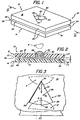
- a device 10 constructed in accordance with one embodiment of the invention comprises (see Fig. 1) two members 12 and 14 having respective exterior surfaces 16 and 18, and respective interior, opposed surfaces 20 and 22.
- the members 12, 14 have boundary edge surfaces 24.
- Surfaces 20 and 22 are spaced apart a distance "x" (see Fig. 2) such that capillary flow of liquid is induced between the surfaces.
- the spaced-apart surfaces 20 and 22 define a transport zone 26 and act as means for transporting introduced liquid between the surfaces.
- a range of values for "x" is permissible, and the exact value depends upon the liquid being transported.
- a preferred means for introducing a drop of liquid into zone 26 is an aperture 30 extending from surface 16 to surface 20, through member 12.
- the aperture 30 comprises a sidewall 32 extending between the surfaces 16 and 20.
- the preferred largest dimension of aperture 30 in plan is one which is about equal to the greatest diameter of the drop expected to be received by the aperture 30.
- the drop diameter is dictated by the volume and surface tension of the drop.
- the volume of the drop should be adequate to fill transport zone 26 to the extent desired. For uses such as clinical analysis as herein described, a convenient drop volume is about 10 ,ul.
- the largest flow-through dimension, measured as described above is preferably about 0.26 cm.
- intersection of surface 16 and sidewall 32 is provided with means that encourage the selected drop of liquid deposited or received in the plane of surface 16 generally at aperture 30, to move into contact with the entire perimeter of sidewall 32.
- sidewall 32 is shaped so as to comprise a plurality of surfaces that intersect, at least at and adjacent surface 16, at predetermined locations to form a plurality of interior corners 34.
- predetermined location or “locations” means locations deliberately chosen, and distinguishes the present invention from cylindrical apertures which inadvertently or accidentally have imperfections, such as microscopic corners, in the sidewall. Such accidental constructs are not capable of providing the substantial urging of the drop into the aperture which the present invention provides. As shown in Fig.
- sidewall 32 comprises throughout its perimeter, six sidewall surfaces and six such predetermined corners 34.
- equal angles of such corners 34 and equal lengths of the intersecting surfaces are selected to provide a shape, when viewed in plan, i.e. perpendicular to the surface 16, that is a regular hexagon, the preferred configuration.
- device 10 In operation (see Fig. 2) device 10 is placed in a drop-displacing zone adjacent to a source of drops.
- a drop A of liquid such as blood serum, or whole blood, is dropped onto the device as a free-form drop or is touched off from a pendant surface onto surface 16 generally at aperture 30.
- the surface 16 preferably is maintained in a generally horizontal orientation during this step. Corners 34 act to centre the drop and urge it into contact with the surfaces of sidewall 32. It then moves down into zone 26 and into contact with surface 22, where capillary attraction further causes the liquid to spread throughout zone 26, (see the arrows 36), so that the bounding meniscus arrives at the position shown in broken lines. Assuming sufficient volume in the drop, the spreading ceases at edge surfaces 24 which define an energy barrier to further capillary flow.
- the drop In order to ensure effective filling of the aperture the drop should be applied to aperture 30 so as to contact one of the corners. The effect is most pronounced when the centre of gravity of the drop is positioned over the aperture 30, rather than over the solid surface 16.
- a second aperture can be formed in either member 12 or 14.
- the corners of the aperture 30, at the surface 16 where the drop is first applied seem to act as centres of force which induce the drop to move into contact with sidewall 32 along its entire perimeter or circumference. That is, referring to Fig. 3, it is believed that the centring force F 3 of a drop A applied at one of the corners 34 is significantly greater than the corresponding centring force F 1 or F 2 that exists for a drop A' placed at any adjacent location 38 or 39 spaced away from a corner 34. At least one corner 34 is needed for the effect. However, at least three corners 34 are preferred, as in Fig. 3, to ensure a greater likelihood'that the drop A will be in contact with a corner 34 when it contacts surface 16.
- a preferred number of corners is between three and about ten. Highly preferred is six corners in a regular hexagon.
- the corners 34 will have a slight radius of curvature.
- they each should have a radius of curvature that is no larger than about 0.4 mm.
- a compound meniscus is one in which the principal radii of curvature of the drop surface vary, depending on the location taken on the surface of the drop. If the drop is properly located at a corner, the compound meniscus forms a drop that extends laterally farther out over the aperture than it does when not located at a corner, and the weight of this extension causes the drop to fall or otherwise move into contact with the perimeter of sidewall 32 and then through the aperture 30. It may also be that there is at the corner a greater tendency for the drop to wet the sidewall than would occur in the absence of a corner.
- aperture 30 will function equally as well if sidewall 32 is smoothed out, as it approaches surface 20, to form a cylinder (not shown).
- Members 12 and 14 can be formed from any suitable material, such as plastics or metal.
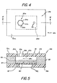
- FIGs. 4 and 5 there is illustrated a second embodiment of the device.
- This second embodiment is one in which a transport chamber is formed for radiometric analysis of an analyte of a biological liquid such as blood. Parts similar to those previously described bear the same reference numeral but with the distinguishing suffix "a" appended.
- Device 10a features a support member 14a (see Fig. 5), a cover member 12a, a spacer member 50 used to adhere members 12a and 14a together, and a radiometrically detectable test element 60 disposed on support 14a.
- the test element 60 is spaced away from member 12a so that there is a transport zone 26a between element 60 and member 12a.
- the spacing between surface 20a and the test element 60 is such as to produce a capillary effect to induce the drop that enters through aperture 30a to spread throughout the zone 26a.
- the test element 60 abuts against the spacer member 50, and is held against member 14a by, for example, adhesive.
- the members 12a, 14a and 50 define a capillary transport chamber containing the test element 60 and having any convenient shape, such as a rectangular chamber when viewed in plan, as in Fig. 4.
- any suitable joining means can be employed between members 12a and 50, and members 50 and 14a.
- a variety of adhesives can be used, or if all the members are thermoplastic, ultrasonic welding or heat-sealing can be used.
- Member 12a is provided with an access aperture 30a extending through the member from its exterior surface 16a to zone 26a, disposed directly above a portion of test element 60. At least that portion of the aperture's sidewall 32a that intersects with surface 16a is provided with corners 34a, as described above. Preferably sidewall 32a is in the cross-sectional shape of a regular hexagon. An additional, cylindrically shaped, aperture 70 in member 12a acts as a vent for expelled air.
- a viewing port 80 is optionally provided in support member 14a, particularly when the latter member is not itself transparent.
- Test element 60 comprises an optional transparent support 62, formed, for example of poly-(ethylene terephthalate), and at least an absorbent layer 64 disposed on support 62.
- Such layer can have a variety of binder compositions, for example, gelatin, cellulose acetate butyrate, polyvinyl alcohol, agarose and the like, the degree of hydrophilicity of which depends upon the material selected. Gelatin is particularly preferred as it acts as a wetting agent to provide for uniform liquid flow through zone 26a. Support 62 can be omitted where adequate support for layer 64 can be obtained from support member 14a.
- layer 66 can be disposed above layer 64 to provide a variety of chemistries or functions, such as to provide, either in layer 66 alone or together with layer 64, a reagent composition. Filtering, registration and mordanting functions can be provided also by such additional layers, such as are described in U.S.-A-4,042,335.
- layer 66 can comprise a reagent, such as an enzyme, and a binder of the same type as is used for layer 64.
- reagent in “reagent composition” means a material that is capable of interaction with an analyte, a precursor of an analyte, a decomposition product of an analyte, or an intermediate.
- one of the reagents can be a preformed, radiometrically detectable species that is caused by the analyte of choice to move out of a radiometrically opaque portion or layer of the element, such as layer 66, into a radiometrically transparent portion or layer, such as a registration layer.
- radiometric detection includes both colorimetric and fluorimetric detection, depending upon the indicator reagent selected for the assay.
- the assay of the element is designed to produce a signal that is proportional to the amount of analyte that is present.
- radiometric assays can be provided by element 60.
- the assays are all oxygen-independent, as the flow of blood or blood serum into zone 26a tends to seal off element 60 from any additional oxygen.
- Typical analytes which can be tested include BUN, total protein, bilirubin and the like.
- the necessary reagents and binder or vehicle compositions for the layers of element 60, such as layers 64 and 66, for these analytes can be those described in, respectively, U.S.-A-4,066,403, 4,132,528 and 4,069,016 or 4,069,017.
- Quantitative detection of the change produced in element 60 by reason of the analyte of the test element is preferably made by scanning the element through port 80 with a photometer or fluorimeter.
- a photometer or fluorimeter A variety of such instruments can be used, for example the radiometer disclosed in DE-A-2,755,334, or the photometer described in U.S.-A-4,119,381.
- Members 12a and 14a are formed from polystyrene of a thickness 0.127 and 0.254 mm, respectively.
- Member 50 is steel of a thickness 0.38 mm.
- the three members are sealed together by adhesives such as polybutyl acrylate adhesive (trademark "Covinax").
- Apertures 30a and 70 in member 12a are about 8 mm apart on centre.
- the outside diameter of the hexagon form of aperture 30a is about 2.6 mm.
- View port 80 is about 5 mm in diameter.
- the capillary spacing between test element 60 and member 12a is about 0.05 mm and the width of element 60 is about 11.5 mm.
- test element 60 designed to detect total protein in a 10 pi drop of blood serum, the following sequential layers are used:
Landscapes
- Chemical & Material Sciences (AREA)
- Health & Medical Sciences (AREA)
- Dispersion Chemistry (AREA)
- Analytical Chemistry (AREA)
- General Health & Medical Sciences (AREA)
- Hematology (AREA)
- Clinical Laboratory Science (AREA)
- Chemical Kinetics & Catalysis (AREA)
- Investigating Or Analysing Biological Materials (AREA)
Claims (8)
Priority Applications (1)
| Application Number | Priority Date | Filing Date | Title |
|---|---|---|---|
| AT79302339T ATE1366T1 (de) | 1978-10-25 | 1979-10-25 | Vorrichtung zum befoerdern einer fluessigkeit. |
Applications Claiming Priority (4)
| Application Number | Priority Date | Filing Date | Title |
|---|---|---|---|
| US954689 | 1978-10-25 | ||
| US05/954,689 US4233029A (en) | 1978-10-25 | 1978-10-25 | Liquid transport device and method |
| US06/059,924 US4254083A (en) | 1979-07-23 | 1979-07-23 | Structural configuration for transport of a liquid drop through an ingress aperture |
| US59924 | 1993-05-10 |
Publications (2)
| Publication Number | Publication Date |
|---|---|
| EP0010456A1 EP0010456A1 (de) | 1980-04-30 |
| EP0010456B1 true EP0010456B1 (de) | 1982-07-28 |
Family
ID=26739368
Family Applications (1)
| Application Number | Title | Priority Date | Filing Date |
|---|---|---|---|
| EP19790302339 Expired EP0010456B1 (de) | 1978-10-25 | 1979-10-25 | Vorrichtung zum Befördern einer Flüssigkeit |
Country Status (3)
| Country | Link |
|---|---|
| EP (1) | EP0010456B1 (de) |
| CA (1) | CA1129498A (de) |
| DE (1) | DE2963436D1 (de) |
Cited By (18)
| Publication number | Priority date | Publication date | Assignee | Title |
|---|---|---|---|---|
| DE3739046A1 (de) * | 1986-11-18 | 1988-05-26 | Hugh V Cottingham | Agglutinationskammer |
| US5997817A (en) * | 1997-12-05 | 1999-12-07 | Roche Diagnostics Corporation | Electrochemical biosensor test strip |
| US7338639B2 (en) | 1997-12-22 | 2008-03-04 | Roche Diagnostics Operations, Inc. | System and method for analyte measurement |
| US7390667B2 (en) | 1997-12-22 | 2008-06-24 | Roche Diagnostics Operations, Inc. | System and method for analyte measurement using AC phase angle measurements |
| US7407811B2 (en) | 1997-12-22 | 2008-08-05 | Roche Diagnostics Operations, Inc. | System and method for analyte measurement using AC excitation |
| US7452457B2 (en) | 2003-06-20 | 2008-11-18 | Roche Diagnostics Operations, Inc. | System and method for analyte measurement using dose sufficiency electrodes |
| US7488601B2 (en) | 2003-06-20 | 2009-02-10 | Roche Diagnostic Operations, Inc. | System and method for determining an abused sensor during analyte measurement |
| US7556723B2 (en) | 2004-06-18 | 2009-07-07 | Roche Diagnostics Operations, Inc. | Electrode design for biosensor |
| US7569126B2 (en) | 2004-06-18 | 2009-08-04 | Roche Diagnostics Operations, Inc. | System and method for quality assurance of a biosensor test strip |
| US7597793B2 (en) | 2003-06-20 | 2009-10-06 | Roche Operations Ltd. | System and method for analyte measurement employing maximum dosing time delay |
| US7604721B2 (en) | 2003-06-20 | 2009-10-20 | Roche Diagnostics Operations, Inc. | System and method for coding information on a biosensor test strip |
| US7645421B2 (en) | 2003-06-20 | 2010-01-12 | Roche Diagnostics Operations, Inc. | System and method for coding information on a biosensor test strip |
| US7645373B2 (en) | 2003-06-20 | 2010-01-12 | Roche Diagnostic Operations, Inc. | System and method for coding information on a biosensor test strip |
| US7718439B2 (en) | 2003-06-20 | 2010-05-18 | Roche Diagnostics Operations, Inc. | System and method for coding information on a biosensor test strip |
| US8058077B2 (en) | 2003-06-20 | 2011-11-15 | Roche Diagnostics Operations, Inc. | Method for coding information on a biosensor test strip |
| US8071384B2 (en) | 1997-12-22 | 2011-12-06 | Roche Diagnostics Operations, Inc. | Control and calibration solutions and methods for their use |
| US8206565B2 (en) | 2003-06-20 | 2012-06-26 | Roche Diagnostics Operation, Inc. | System and method for coding information on a biosensor test strip |
| US8298828B2 (en) | 2003-06-20 | 2012-10-30 | Roche Diagnostics Operations, Inc. | System and method for determining the concentration of an analyte in a sample fluid |
Families Citing this family (27)
| Publication number | Priority date | Publication date | Assignee | Title |
|---|---|---|---|---|
| DE3134611A1 (de) * | 1981-09-01 | 1983-03-10 | Boehringer Mannheim Gmbh, 6800 Mannheim | Verfahren zur durchfuehrung analytischer bestimmungen und hierfuer geeignetes mittel |
| US4439526A (en) * | 1982-07-26 | 1984-03-27 | Eastman Kodak Company | Clustered ingress apertures for capillary transport devices and method of use |
| GB8406752D0 (en) * | 1984-03-15 | 1984-04-18 | Unilever Plc | Chemical and clinical tests |
| AU588245B2 (en) * | 1984-06-13 | 1989-09-14 | Inverness Medical Switzerland Gmbh | Devices for use in chemical test procedures |
| US4596695A (en) * | 1984-09-10 | 1986-06-24 | Cottingham Hugh V | Agglutinographic reaction chamber |
| US4731335A (en) * | 1985-09-13 | 1988-03-15 | Fisher Scientific Company | Method for treating thin samples on a surface employing capillary flow |
| US5002736A (en) * | 1987-03-31 | 1991-03-26 | Fisher Scientific Co. | Microscope slide and slide assembly |
| DE3889885T2 (de) * | 1987-12-23 | 1994-12-15 | Abbott Lab | Vorrichtung zur Agglutinierungsreaktion. |
| US5051237A (en) * | 1988-06-23 | 1991-09-24 | P B Diagnostic Systems, Inc. | Liquid transport system |
| EP0388782A1 (de) * | 1989-03-20 | 1990-09-26 | Quantai Biotronics Inc. | Verfahren zum Nachweis von Analyten |
| SE470347B (sv) * | 1990-05-10 | 1994-01-31 | Pharmacia Lkb Biotech | Mikrostruktur för vätskeflödessystem och förfarande för tillverkning av ett sådant system |
| HU9301278D0 (en) * | 1990-10-30 | 1993-09-28 | Hypoguard Ltd | Collecting and signalling device |
| GB9218118D0 (en) * | 1992-08-26 | 1992-10-14 | Hypoguard Uk Ltd | Device |
| US5278079A (en) * | 1992-09-02 | 1994-01-11 | Enzymatics, Inc. | Sealing device and method for inhibition of flow in capillary measuring devices |
| US5820826A (en) * | 1992-09-03 | 1998-10-13 | Boehringer Mannheim Company | Casing means for analytical test apparatus |
| EP0737104A1 (de) * | 1993-12-28 | 1996-10-16 | Abbott Laboratories | Vorrichtungen mit durchfluss unter ihrer oberflaeche zur diagnostischen analyse |
| US5872010A (en) * | 1995-07-21 | 1999-02-16 | Northeastern University | Microscale fluid handling system |
| DE19753847A1 (de) * | 1997-12-04 | 1999-06-10 | Roche Diagnostics Gmbh | Analytisches Testelement mit Kapillarkanal |
| DE19753850A1 (de) * | 1997-12-04 | 1999-06-10 | Roche Diagnostics Gmbh | Probennahmevorrichtung |
| GB2385014B (en) | 1999-06-21 | 2003-10-15 | Micro Chemical Systems Ltd | Method of preparing a working solution |
| DE10002500A1 (de) * | 2000-01-21 | 2001-07-26 | Univ Albert Ludwigs Freiburg | Kapillarkraftmischer |
| US6997343B2 (en) | 2001-11-14 | 2006-02-14 | Hypoguard Limited | Sensor dispensing device |
| US7250095B2 (en) | 2002-07-11 | 2007-07-31 | Hypoguard Limited | Enzyme electrodes and method of manufacture |
| WO2004036202A1 (en) | 2002-10-16 | 2004-04-29 | Cellectricon Ab | Nanoelectrodes and nanotips for recording transmembrane currents in a plurality of cells |
| US7264139B2 (en) | 2003-01-14 | 2007-09-04 | Hypoguard Limited | Sensor dispensing device |
| DE10356752A1 (de) | 2003-12-04 | 2005-06-30 | Roche Diagnostics Gmbh | Beschichtete Testelemente |
| AU2014352964B2 (en) | 2013-11-22 | 2018-12-06 | Rheonix, Inc. | Channel-less pump, methods, and applications thereof |
Family Cites Families (4)
| Publication number | Priority date | Publication date | Assignee | Title |
|---|---|---|---|---|
| FR1444146A (fr) * | 1965-05-14 | 1966-07-01 | Promoveo | Perfectionnements aux dispositifs pour l'étude des réactions chimiques ou biologiques |
| DE1617732C2 (de) * | 1966-03-01 | 1972-12-21 | Promoveo-Sobioda & Cie, Seyssinet (Frankreich) | Vorrichtung zur Untersuchung lebender Zellen von Mikroorganismen |
| US3565537A (en) * | 1968-10-30 | 1971-02-23 | Jack Fielding | Specimen holder for example for testing the colour of a liquid such as blood |
| US3992158A (en) * | 1973-08-16 | 1976-11-16 | Eastman Kodak Company | Integral analytical element |
-
1979
- 1979-10-24 CA CA338,319A patent/CA1129498A/en not_active Expired
- 1979-10-25 EP EP19790302339 patent/EP0010456B1/de not_active Expired
- 1979-10-25 DE DE7979302339T patent/DE2963436D1/de not_active Expired
Cited By (33)
| Publication number | Priority date | Publication date | Assignee | Title |
|---|---|---|---|---|
| DE3739046A1 (de) * | 1986-11-18 | 1988-05-26 | Hugh V Cottingham | Agglutinationskammer |
| USRE41309E1 (en) | 1997-12-05 | 2010-05-04 | Roche Diagnostics Operations, Inc. | Electrochemical biosensor test strip |
| US5997817A (en) * | 1997-12-05 | 1999-12-07 | Roche Diagnostics Corporation | Electrochemical biosensor test strip |
| USRE43815E1 (en) | 1997-12-05 | 2012-11-20 | Roche Diagnostics Operations, Inc. | Electrochemical biosensor test strip |
| USRE42953E1 (en) | 1997-12-05 | 2011-11-22 | Roche Diagnostics Operations, Inc. | Electrochemical biosensor test strip |
| USRE42924E1 (en) | 1997-12-05 | 2011-11-15 | Roche Diagnostics Operations, Inc. | Electrochemical biosensor test strip |
| USRE42560E1 (en) | 1997-12-05 | 2011-07-19 | Roche Diagnostics Operations, Inc. | Electrochemical biosensor test strip |
| US7338639B2 (en) | 1997-12-22 | 2008-03-04 | Roche Diagnostics Operations, Inc. | System and method for analyte measurement |
| US7390667B2 (en) | 1997-12-22 | 2008-06-24 | Roche Diagnostics Operations, Inc. | System and method for analyte measurement using AC phase angle measurements |
| US7407811B2 (en) | 1997-12-22 | 2008-08-05 | Roche Diagnostics Operations, Inc. | System and method for analyte measurement using AC excitation |
| US7494816B2 (en) | 1997-12-22 | 2009-02-24 | Roche Diagnostic Operations, Inc. | System and method for determining a temperature during analyte measurement |
| US8071384B2 (en) | 1997-12-22 | 2011-12-06 | Roche Diagnostics Operations, Inc. | Control and calibration solutions and methods for their use |
| US8206565B2 (en) | 2003-06-20 | 2012-06-26 | Roche Diagnostics Operation, Inc. | System and method for coding information on a biosensor test strip |
| US8507289B1 (en) | 2003-06-20 | 2013-08-13 | Roche Diagnostics Operations, Inc. | System and method for coding information on a biosensor test strip |
| US7645421B2 (en) | 2003-06-20 | 2010-01-12 | Roche Diagnostics Operations, Inc. | System and method for coding information on a biosensor test strip |
| US7718439B2 (en) | 2003-06-20 | 2010-05-18 | Roche Diagnostics Operations, Inc. | System and method for coding information on a biosensor test strip |
| US7977112B2 (en) | 2003-06-20 | 2011-07-12 | Roche Diagnostics Operations, Inc. | System and method for determining an abused sensor during analyte measurement |
| US7604721B2 (en) | 2003-06-20 | 2009-10-20 | Roche Diagnostics Operations, Inc. | System and method for coding information on a biosensor test strip |
| US8058077B2 (en) | 2003-06-20 | 2011-11-15 | Roche Diagnostics Operations, Inc. | Method for coding information on a biosensor test strip |
| US7597793B2 (en) | 2003-06-20 | 2009-10-06 | Roche Operations Ltd. | System and method for analyte measurement employing maximum dosing time delay |
| US8859293B2 (en) | 2003-06-20 | 2014-10-14 | Roche Diagnostics Operations, Inc. | Method for determining whether a disposable, dry regent, electrochemical test strip is unsuitable for use |
| US8663442B2 (en) | 2003-06-20 | 2014-03-04 | Roche Diagnostics Operations, Inc. | System and method for analyte measurement using dose sufficiency electrodes |
| US8083993B2 (en) | 2003-06-20 | 2011-12-27 | Riche Diagnostics Operations, Inc. | System and method for coding information on a biosensor test strip |
| US8586373B2 (en) | 2003-06-20 | 2013-11-19 | Roche Diagnostics Operations, Inc. | System and method for determining the concentration of an analyte in a sample fluid |
| US7488601B2 (en) | 2003-06-20 | 2009-02-10 | Roche Diagnostic Operations, Inc. | System and method for determining an abused sensor during analyte measurement |
| US8293538B2 (en) | 2003-06-20 | 2012-10-23 | Roche Diagnostics Operations, Inc. | System and method for coding information on a biosensor test strip |
| US8298828B2 (en) | 2003-06-20 | 2012-10-30 | Roche Diagnostics Operations, Inc. | System and method for determining the concentration of an analyte in a sample fluid |
| US7452457B2 (en) | 2003-06-20 | 2008-11-18 | Roche Diagnostics Operations, Inc. | System and method for analyte measurement using dose sufficiency electrodes |
| US7645373B2 (en) | 2003-06-20 | 2010-01-12 | Roche Diagnostic Operations, Inc. | System and method for coding information on a biosensor test strip |
| US8092668B2 (en) | 2004-06-18 | 2012-01-10 | Roche Diagnostics Operations, Inc. | System and method for quality assurance of a biosensor test strip |
| US7556723B2 (en) | 2004-06-18 | 2009-07-07 | Roche Diagnostics Operations, Inc. | Electrode design for biosensor |
| US7569126B2 (en) | 2004-06-18 | 2009-08-04 | Roche Diagnostics Operations, Inc. | System and method for quality assurance of a biosensor test strip |
| US9410915B2 (en) | 2004-06-18 | 2016-08-09 | Roche Operations Ltd. | System and method for quality assurance of a biosensor test strip |
Also Published As
| Publication number | Publication date |
|---|---|
| EP0010456A1 (de) | 1980-04-30 |
| DE2963436D1 (en) | 1982-09-16 |
| CA1129498A (en) | 1982-08-10 |
Similar Documents
| Publication | Publication Date | Title |
|---|---|---|
| EP0010456B1 (de) | Vorrichtung zum Befördern einer Flüssigkeit | |
| US4254083A (en) | Structural configuration for transport of a liquid drop through an ingress aperture | |
| EP0034049B1 (de) | Vorrichtung zum Durchführen einer Mehrfachanalyse | |
| US7238534B1 (en) | Capillary active test element having an intermediate layer situated between the support and the covering | |
| EP0057110B2 (de) | Reaktionsgefäss und Verfahren, um Flüssigkeiten und Reagenzien miteinander in Kontakt zu bringen | |
| US5225163A (en) | Reaction apparatus employing gravitational flow | |
| US5006309A (en) | Immunoassay device with liquid transfer between wells by washing | |
| CA1119831A (en) | Liquid transport device and method | |
| US6197597B1 (en) | Solid phase immunoassay with carriers matching the shape of sample wells | |
| CN1638871B (zh) | 通过离心力和/或毛细力精确输送和操作流体的方法和装置 | |
| EP0206561B1 (de) | Diagnostischer Apparat | |
| CA2156412A1 (en) | Disposable device in diagnostic assays | |
| JPH0582552B2 (de) | ||
| EP0228285A1 (de) | Teststreifen | |
| JP2004361421A (ja) | 容器 | |
| EP1803659A1 (de) | Teststreifenverpackung, Behälter und Herstellungsverfahren für die Teststreifenverpackung | |
| AU744163B2 (en) | Device for the capillary transport of liquid | |
| WO2001024931A1 (en) | Capillary device for separating undesired components from a liquid sample and related method | |
| US8652407B1 (en) | Self-contained assay device | |
| KR20030070913A (ko) | 시험 장치 | |
| AU691943B2 (en) | Analytical dipstick for improved mixing and reduced reagent volume | |
| JP2004125545A (ja) | 分析方法及び装置 | |
| JP2004361422A (ja) | 容器 | |
| MXPA00005418A (en) | Device for the capillary transport of liquid | |
| GB2339904A (en) | Membrane carrying assay areas |
Legal Events
| Date | Code | Title | Description |
|---|---|---|---|
| PUAI | Public reference made under article 153(3) epc to a published international application that has entered the european phase |
Free format text: ORIGINAL CODE: 0009012 |
|
| AK | Designated contracting states |
Designated state(s): AT BE CH DE FR GB IT NL SE |
|
| DET | De: translation of patent claims | ||
| 17P | Request for examination filed |
Effective date: 19801016 |
|
| ITF | It: translation for a ep patent filed | ||
| GRAA | (expected) grant |
Free format text: ORIGINAL CODE: 0009210 |
|
| AK | Designated contracting states |
Designated state(s): AT BE CH DE FR GB IT NL SE |
|
| REF | Corresponds to: |
Ref document number: 1366 Country of ref document: AT Date of ref document: 19820815 Kind code of ref document: T |
|
| REF | Corresponds to: |
Ref document number: 2963436 Country of ref document: DE Date of ref document: 19820916 |
|
| PGFP | Annual fee paid to national office [announced via postgrant information from national office to epo] |
Ref country code: AT Payment date: 19911007 Year of fee payment: 13 |
|
| ITTA | It: last paid annual fee | ||
| PGFP | Annual fee paid to national office [announced via postgrant information from national office to epo] |
Ref country code: NL Payment date: 19911031 Year of fee payment: 13 |
|
| PG25 | Lapsed in a contracting state [announced via postgrant information from national office to epo] |
Ref country code: AT Effective date: 19921025 |
|
| PG25 | Lapsed in a contracting state [announced via postgrant information from national office to epo] |
Ref country code: NL Effective date: 19930501 |
|
| NLV4 | Nl: lapsed or anulled due to non-payment of the annual fee | ||
| EAL | Se: european patent in force in sweden |
Ref document number: 79302339.1 |
|
| BECN | Be: change of holder's name |
Effective date: 19950906 |
|
| REG | Reference to a national code |
Ref country code: GB Ref legal event code: 732E |
|
| PGFP | Annual fee paid to national office [announced via postgrant information from national office to epo] |
Ref country code: FR Payment date: 19971009 Year of fee payment: 19 |
|
| PGFP | Annual fee paid to national office [announced via postgrant information from national office to epo] |
Ref country code: GB Payment date: 19971016 Year of fee payment: 19 |
|
| PGFP | Annual fee paid to national office [announced via postgrant information from national office to epo] |
Ref country code: DE Payment date: 19971031 Year of fee payment: 19 |
|
| PGFP | Annual fee paid to national office [announced via postgrant information from national office to epo] |
Ref country code: CH Payment date: 19971106 Year of fee payment: 19 |
|
| PGFP | Annual fee paid to national office [announced via postgrant information from national office to epo] |
Ref country code: BE Payment date: 19980630 Year of fee payment: 20 |
|
| PGFP | Annual fee paid to national office [announced via postgrant information from national office to epo] |
Ref country code: SE Payment date: 19981019 Year of fee payment: 20 |
|
| PG25 | Lapsed in a contracting state [announced via postgrant information from national office to epo] |
Ref country code: GB Free format text: LAPSE BECAUSE OF NON-PAYMENT OF DUE FEES Effective date: 19981025 |
|
| PG25 | Lapsed in a contracting state [announced via postgrant information from national office to epo] |
Ref country code: CH Free format text: LAPSE BECAUSE OF NON-PAYMENT OF DUE FEES Effective date: 19981031 |
|
| BE20 | Be: patent expired |
Free format text: 19991025 *JOHNSON & JOHNSON CLINICAL DIAGNOSTICS INC. |
|
| REG | Reference to a national code |
Ref country code: CH Ref legal event code: PL |
|
| GBPC | Gb: european patent ceased through non-payment of renewal fee |
Effective date: 19981025 |
|
| PG25 | Lapsed in a contracting state [announced via postgrant information from national office to epo] |
Ref country code: FR Free format text: LAPSE BECAUSE OF NON-PAYMENT OF DUE FEES Effective date: 19990630 |
|
| REG | Reference to a national code |
Ref country code: FR Ref legal event code: ST |
|
| PG25 | Lapsed in a contracting state [announced via postgrant information from national office to epo] |
Ref country code: DE Free format text: LAPSE BECAUSE OF NON-PAYMENT OF DUE FEES Effective date: 19990803 |
|
| PG25 | Lapsed in a contracting state [announced via postgrant information from national office to epo] |
Ref country code: SE Free format text: LAPSE BECAUSE OF NON-PAYMENT OF DUE FEES Effective date: 19991026 |
|
| EUG | Se: european patent has lapsed |
Ref document number: 79302339.1 |
|
| PLBE | No opposition filed within time limit |
Free format text: ORIGINAL CODE: 0009261 |
|
| STAA | Information on the status of an ep patent application or granted ep patent |
Free format text: STATUS: NO OPPOSITION FILED WITHIN TIME LIMIT |