EP0010286B1 - Cooled panels for walls of electric furnaces - Google Patents
Cooled panels for walls of electric furnaces Download PDFInfo
- Publication number
- EP0010286B1 EP0010286B1 EP79103972A EP79103972A EP0010286B1 EP 0010286 B1 EP0010286 B1 EP 0010286B1 EP 79103972 A EP79103972 A EP 79103972A EP 79103972 A EP79103972 A EP 79103972A EP 0010286 B1 EP0010286 B1 EP 0010286B1
- Authority
- EP
- European Patent Office
- Prior art keywords
- elements
- panel
- furnace
- panel according
- panels
- Prior art date
- Legal status (The legal status is an assumption and is not a legal conclusion. Google has not performed a legal analysis and makes no representation as to the accuracy of the status listed.)
- Expired
Links
- 239000011819 refractory material Substances 0.000 claims abstract description 9
- 238000001816 cooling Methods 0.000 claims description 7
- 239000002893 slag Substances 0.000 claims description 5
- 238000003466 welding Methods 0.000 claims description 5
- 238000000034 method Methods 0.000 claims 1
- XLYOFNOQVPJJNP-UHFFFAOYSA-N water Substances O XLYOFNOQVPJJNP-UHFFFAOYSA-N 0.000 abstract description 8
- 239000011449 brick Substances 0.000 abstract description 4
- 239000000463 material Substances 0.000 abstract description 2
- 239000012530 fluid Substances 0.000 description 4
- 238000003723 Smelting Methods 0.000 description 3
- 229910000831 Steel Inorganic materials 0.000 description 2
- 230000006978 adaptation Effects 0.000 description 2
- 238000005452 bending Methods 0.000 description 2
- 238000005266 casting Methods 0.000 description 2
- 239000012809 cooling fluid Substances 0.000 description 2
- 239000000498 cooling water Substances 0.000 description 2
- 238000005265 energy consumption Methods 0.000 description 2
- 239000011810 insulating material Substances 0.000 description 2
- 238000010079 rubber tapping Methods 0.000 description 2
- 239000010959 steel Substances 0.000 description 2
- 239000000654 additive Substances 0.000 description 1
- 230000000996 additive effect Effects 0.000 description 1
- 230000003247 decreasing effect Effects 0.000 description 1
- 238000009413 insulation Methods 0.000 description 1
- 239000007788 liquid Substances 0.000 description 1
- 238000004519 manufacturing process Methods 0.000 description 1
- 238000013021 overheating Methods 0.000 description 1
- 238000009877 rendering Methods 0.000 description 1
Images


Classifications
-
- F—MECHANICAL ENGINEERING; LIGHTING; HEATING; WEAPONS; BLASTING
- F27—FURNACES; KILNS; OVENS; RETORTS
- F27B—FURNACES, KILNS, OVENS OR RETORTS IN GENERAL; OPEN SINTERING OR LIKE APPARATUS
- F27B3/00—Hearth-type furnaces, e.g. of reverberatory type; Electric arc furnaces ; Tank furnaces
- F27B3/10—Details, accessories or equipment, e.g. dust-collectors, specially adapted for hearth-type furnaces
- F27B3/24—Cooling arrangements
-
- F—MECHANICAL ENGINEERING; LIGHTING; HEATING; WEAPONS; BLASTING
- F27—FURNACES; KILNS; OVENS; RETORTS
- F27D—DETAILS OR ACCESSORIES OF FURNACES, KILNS, OVENS OR RETORTS, IN SO FAR AS THEY ARE OF KINDS OCCURRING IN MORE THAN ONE KIND OF FURNACE
- F27D1/00—Casings; Linings; Walls; Roofs
- F27D1/12—Casings; Linings; Walls; Roofs incorporating cooling arrangements
-
- F—MECHANICAL ENGINEERING; LIGHTING; HEATING; WEAPONS; BLASTING
- F27—FURNACES; KILNS; OVENS; RETORTS
- F27D—DETAILS OR ACCESSORIES OF FURNACES, KILNS, OVENS OR RETORTS, IN SO FAR AS THEY ARE OF KINDS OCCURRING IN MORE THAN ONE KIND OF FURNACE
- F27D1/00—Casings; Linings; Walls; Roofs
- F27D1/14—Supports for linings
- F27D1/145—Assembling elements
-
- F—MECHANICAL ENGINEERING; LIGHTING; HEATING; WEAPONS; BLASTING
- F27—FURNACES; KILNS; OVENS; RETORTS
- F27D—DETAILS OR ACCESSORIES OF FURNACES, KILNS, OVENS OR RETORTS, IN SO FAR AS THEY ARE OF KINDS OCCURRING IN MORE THAN ONE KIND OF FURNACE
- F27D9/00—Cooling of furnaces or of charges therein
- F27D2009/0002—Cooling of furnaces
- F27D2009/0045—Cooling of furnaces the cooling medium passing a block, e.g. metallic
- F27D2009/0048—Cooling of furnaces the cooling medium passing a block, e.g. metallic incorporating conduits for the medium
Definitions
- This invention relates to panels cooled by water or other suitable liquid for forming the walls of electric furnaces, wherein, as well known, smelting takes place by electric discharges.
- An ideal panel which may be part of a wall or may form the whole wall of an electric furnace should fulfill the following requirements:
- steel blocks are used as having a built-in inner coil.
- the water path is fixed therein, thus assuring a smooth flow, but the disadvantage arises that the panel smelting involves a complicated operation, the reduced size of the panel causing the increase of outside connections.
- a further disadvantage is that during use the considerable size of the panel causes cracks on the melted inner wall thereof. In this case, it is also required to provide panels for. each specific requirement. Thus, different panels should be provided for each type of furnace and in a same furnace panels which are different as to characteristics and size according to the different use zones or sites.
- the U.S.A. Patent 3.829.595 shows a furnace of single piece panel containing their tubes, even these being in a single piece.
- the tubes contained in these panels are connected to one another.
- the object of the present invention is to make panels
- these elements comprise an outer body which is inserted over a special tube or by a tube portion which is incorporated in an outer body, said tubes serving for the passage or cooling water or other fluid.
- a preferred solution also provides that the panel surface facing inwardly of the furnace is shaped so as to retain therein insulating material comprising slags produced by the furnace itself, or refractory material which is suitably before hand.
- the modular elements are assembled by welding to some of the elements comprising curves or bendings some tube lengths over which one or more elements provided with corresponding holes are inserted, then further curved elements are welded to the free ends of said tubes, thus providing a circuit or path for the cooling fluid.
- Such a formed panel can now be bent for adaptation to the diameter of the furnace to which it will be applied.
- portions of refractory material can be incorprated between the various modular elements.
- Fig. 1 shows a portion of a wall of a furnace, in which a portion of a panel 1 is shown at right to line IV--IV, while a portion of a panel 18 adjacent to the first mentioned panel is shown at the left to line IV-IV.
- the supporting structure comprising two vertical tie rods 13 passing into holes 19 suitably provided in each of the modular elements. Said tie rods 13 are then secured to the furnace housing 14.
- Each panel comprises several modular elements, which will now be described one by one.
- Element 2 (Figs. 1, 2 and 3) comprises a block containing two parallel holes shown at 2a respectively, in which tubes 16 are inserted during assembling.
- Elements 3 and.4 (Figs. 1 and 4) comprise blocks containing curved or bent tubes 3t and 4t, respectively.
- Element 6 is quite similar to element 2, but the distance or spacing between the parallel holes 6a, and hence between tubes 16 therein contained is larger than that between tubes 16 of said element 2.
- Element 5 comprises a semi- element having a single hole 5a and is for completion of the panel.
- element 15 is similar to element 5, but comprises a curved element 15a connected to tube 8 or 9, respectively serving for the return and delivery of the cooling fluid.
- the assembling of the various elements, so that the latter will form a panel may be effected by merely taking elements 3 or 4 comprising a curve or bending, preferably projecting out of the element, and welding on these tube ends some lengths of straight tube 16 of a suitable size, then inserting on such straight tubes the preselected elements, such as those of type 2, 6 or the like, finally welding to the end of these straight tubes other curved tubes 3a or 4a, and two elements 15, 1 5a with associated tube 8 and 9, thus forming a continuous circuit panel.
- the panel thus obtained will be curved for adaptation to the furnace diameter.
- refractory bricks 7 are incorporated in the panel, bricks which are supported by the adjoining elements.
- gaps 10 and 11 in the vertical and horizontal joint zones, respectively, between two adjoining elements are filled with refractory material or simply with slags produced by the furnace operation, thus rendering the structure sufficiently monolithic.
- the side wall of the furnace shown in Fig. 5 comprises nine panels, of which six are for example of a length L1 of 1910 mm and a height H of 1200 mm, two are of a length L2 of 1680 mm and a height H2 of 950 mm, and finally one of a length L3 of 920 mm and a height H3 of 530 mm.
- the asembly of these panels may form the side walls of an electric furnace of about 50t, the circumference T of which is 16,014 mm.
- reference numeral 26 denotes the tapping hole and 17 the casting or pouring level. Above this level, the side walls of the furnace first comprise a refractory 12 of a minimal height H4 of 550 mm, this height increasing in proximity of tapping hole 26 and of the gate for the admission of additive materials.
- Fig. 5 three panels have been shown along with the structural modular elements thereof, the water circuit having been shown by arrows and dashed lines indicating the path for the tubes in the elements.
- the elements are arranged so as to be offset in height, each row relative to the adjacent row, but this is not the only possible solution, as shown in one of the panels of Fig. 5.
- the darkened zones in each of the panels are those in which refractory material 7 has been inserted.
- panels can be provided of different characteristics along the height thereof, having for example lower zones with a larger cooling factor than that of the upper zones, as predicated. This can be done only because of the availability of small modular casting elements.
- the furnace cooling can be differentiately balanced: at the hot locations, a higher cooling is provided, while at those less liable to heat, cooling is smaller.
- each element is formed with cavities 2b and 6b, in which refractory material is inserted, and in any case against which the furnace slags will deposit, thus increasing the wall insulation and hence decreasing the heat exchange and increasing the panel life.
- cavities may be of any shape and pattern as far as capable of retaining the insulating material.
- refractory bricks along with cavities 2b and 6b carrying refractory material or slags allows a lower removal of calories from the cooling water and accordingly a lower energy consumption for steel smelting.
Landscapes
- Engineering & Computer Science (AREA)
- Mechanical Engineering (AREA)
- General Engineering & Computer Science (AREA)
- Furnace Housings, Linings, Walls, And Ceilings (AREA)
- Vertical, Hearth, Or Arc Furnaces (AREA)
- Furnace Details (AREA)
- Cartons (AREA)
Abstract
Description
- This invention relates to panels cooled by water or other suitable liquid for forming the walls of electric furnaces, wherein, as well known, smelting takes place by electric discharges.
- An ideal panel, which may be part of a wall or may form the whole wall of an electric furnace should fulfill the following requirements:
- (1) Provide minimal heat losses through the panel.
- (2) Provide the greatest possible safety against any accidental exit of water or other fluid.
- (3) Be of a big anough size, so that only a reduced number of outside connections has to be carried out for the supply and discharge of water or other fluids.
- (4) Be of a suitable size and having thermal characteristics according to each site or zone of each furnace.
- (5) Enable a long life of the panel in use.
- (6) Allow the partial replacement of zones of the panel according to requirements and as desired.
- Different types of panel are commercially available, but the solutions hitherto proposed only partly meet these conditions. Particularly, boxes or sectors are used as panels for electric furnaces having water circulating therein, but this fluid, though it has fixed paths, may, due to the provision of not circular sections, easily build up pockets of steam or dead water causing overheating of some zones of the boxes and accordingly a perforation thereof.
- Also steel blocks are used as having a built-in inner coil. The water path is fixed therein, thus assuring a smooth flow, but the disadvantage arises that the panel smelting involves a complicated operation, the reduced size of the panel causing the increase of outside connections. A further disadvantage is that during use the considerable size of the panel causes cracks on the melted inner wall thereof. In this case, it is also required to provide panels for. each specific requirement. Thus, different panels should be provided for each type of furnace and in a same furnace panels which are different as to characteristics and size according to the different use zones or sites.
- The U.S.A. Patent 3.829.595 shows a furnace of single piece panel containing their tubes, even these being in a single piece. The tubes contained in these panels are connected to one another.
- These traditional panels must have a reduced size for avoiding cracks when they are subjected to thermal expansion and for adapting themselves to the ideal profile of the furnace surface which is to be coated. Moreover the traditional panel must be manufactured also considering its constructive requirements.
- These requirements are in contrast with the furnace requirements due to the fact that the panel in the nearest zone to the bath must disperse more heat than a panel in a zone further off from the same. The U.S.A. patent provides therefore a panel which is a compromise which satisfies only partially the local thermal requirements of the furnace. Further due to the relatively small size of the panel according to the U.S.A. patent a plurality of external connections of the tubes must be provided, which results difficult and expensive. Moreover according to the U.S.A. patent one must construct different panels for each size of the furnace.
- Therefore the object of the present invention is to make panels
- a) which are perfectly adapted to the local thermal requirements of each furnace providing an optimum heat-exchange and therefore resulting in a low energy consumption;
- b) which have considerable size without presenting any breakages due to thermal expansion;
- c) which have reduced manufacturing expenses, making use of a small series of elements adaptable to any furnace diameter, these elements thus being independent of the furnace diameter;
- d) which have a long life;
- e) which allow the replacement even of a single zone of the panel.
- These objects have been obtained as specified in the claims.
- Preferably, these elements comprise an outer body which is inserted over a special tube or by a tube portion which is incorporated in an outer body, said tubes serving for the passage or cooling water or other fluid.
- A preferred solution also provides that the panel surface facing inwardly of the furnace is shaped so as to retain therein insulating material comprising slags produced by the furnace itself, or refractory material which is suitably before hand.
- Preferably, the modular elements are assembled by welding to some of the elements comprising curves or bendings some tube lengths over which one or more elements provided with corresponding holes are inserted, then further curved elements are welded to the free ends of said tubes, thus providing a circuit or path for the cooling fluid. Such a formed panel can now be bent for adaptation to the diameter of the furnace to which it will be applied.
- In case, portions of refractory material can be incorprated between the various modular elements.
- The invention will now be more clearly explained with reference to an exemplary embodiment which has been shown in the figures of the accompanying drawings, in which:
- Fig. 1 is a front view of a portion of two walls for an electric furnace according to the present invention;
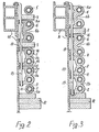
- Fig. 2 is a sectional view taken along line II-II of Fig. 1;
- Fig. 3 is a sectional view taken along line III-Ill of Fig. 1;
- Fig. 4 is a view taken along line IV-IV of Fig. 1; and
- Fig. 5 is a developed view of a wall of a furnace lined up with panels according to the present invention.
- Fig. 1 shows a portion of a wall of a furnace, in which a portion of a panel 1 is shown at right to line IV--IV, while a portion of a panel 18 adjacent to the first mentioned panel is shown at the left to line IV-IV.
- In the zone underlying said two panels, there is a
refractory base 12. In Fiugs. 2, 3 and 4 there is also shown the supporting structure comprising twovertical tie rods 13 passing intoholes 19 suitably provided in each of the modular elements. Saidtie rods 13 are then secured to thefurnace housing 14. - Each panel comprises several modular elements, which will now be described one by one.
- Element 2 (Figs. 1, 2 and 3) comprises a block containing two parallel holes shown at 2a respectively, in which
tubes 16 are inserted during assembling.Elements 3 and.4 (Figs. 1 and 4) comprise blocks containing curved or bent tubes 3t and 4t, respectively.Element 6 is quite similar toelement 2, but the distance or spacing between the parallel holes 6a, and hence betweentubes 16 therein contained is larger than that betweentubes 16 ofsaid element 2.Element 5 comprises a semi- element having a single hole 5a and is for completion of the panel. Finally,element 15 is similar toelement 5, but comprises a curved element 15a connected totube 8 or 9, respectively serving for the return and delivery of the cooling fluid. - The assembling of the various elements, so that the latter will form a panel, may be effected by merely taking
elements 3 or 4 comprising a curve or bending, preferably projecting out of the element, and welding on these tube ends some lengths ofstraight tube 16 of a suitable size, then inserting on such straight tubes the preselected elements, such as those oftype elements 15, 1 5a with associatedtube 8 and 9, thus forming a continuous circuit panel. Now the panel thus obtained will be curved for adaptation to the furnace diameter. In case,refractory bricks 7 are incorporated in the panel, bricks which are supported by the adjoining elements. - The
gaps - The side wall of the furnace shown in Fig. 5 comprises nine panels, of which six are for example of a length L1 of 1910 mm and a height H of 1200 mm, two are of a length L2 of 1680 mm and a height H2 of 950 mm, and finally one of a length L3 of 920 mm and a height H3 of 530 mm. The asembly of these panels may form the side walls of an electric furnace of about 50t, the circumference T of which is 16,014 mm. In the drawing of Fig. 5, reference numeral 26 denotes the tapping hole and 17 the casting or pouring level. Above this level, the side walls of the furnace first comprise a refractory 12 of a minimal height H4 of 550 mm, this height increasing in proximity of tapping hole 26 and of the gate for the admission of additive materials.
- in Fig. 5 three panels have been shown along with the structural modular elements thereof, the water circuit having been shown by arrows and dashed lines indicating the path for the tubes in the elements. Generally, the elements are arranged so as to be offset in height, each row relative to the adjacent row, but this is not the only possible solution, as shown in one of the panels of Fig. 5.
- The darkened zones in each of the panels are those in which
refractory material 7 has been inserted. - From the foregoing description, it will be appreciated that panels can be provided of different characteristics along the height thereof, having for example lower zones with a larger cooling factor than that of the upper zones, as predicated. This can be done only because of the availability of small modular casting elements.
- By this principle, the furnace cooling can be differentiately balanced: at the hot locations, a higher cooling is provided, while at those less liable to heat, cooling is smaller.
- From Figs. 2 and 3, it will be also appreciated that the surface of each element is formed with
cavities - The provision of refractory bricks along with
cavities
Claims (6)
Priority Applications (1)
| Application Number | Priority Date | Filing Date | Title |
|---|---|---|---|
| AT79103972T ATE3587T1 (en) | 1978-10-23 | 1979-10-15 | REFRIGERATION UNIT FOR THE WALLS OF ELECTRIC OVENS. |
Applications Claiming Priority (2)
| Application Number | Priority Date | Filing Date | Title |
|---|---|---|---|
| IT2900778 | 1978-10-23 | ||
| IT29007/78A IT1160001B (en) | 1978-10-23 | 1978-10-23 | COOLED PANELS FOR ELECTRIC OVEN WALLS |
Publications (2)
| Publication Number | Publication Date |
|---|---|
| EP0010286A1 EP0010286A1 (en) | 1980-04-30 |
| EP0010286B1 true EP0010286B1 (en) | 1983-05-25 |
Family
ID=11225650
Family Applications (1)
| Application Number | Title | Priority Date | Filing Date |
|---|---|---|---|
| EP79103972A Expired EP0010286B1 (en) | 1978-10-23 | 1979-10-15 | Cooled panels for walls of electric furnaces |
Country Status (5)
| Country | Link |
|---|---|
| EP (1) | EP0010286B1 (en) |
| AT (1) | ATE3587T1 (en) |
| DE (1) | DE2965520D1 (en) |
| ES (1) | ES246367Y (en) |
| IT (1) | IT1160001B (en) |
Families Citing this family (5)
| Publication number | Priority date | Publication date | Assignee | Title |
|---|---|---|---|---|
| US4435814A (en) * | 1982-01-29 | 1984-03-06 | Bbc Brown, Boveri & Company, Limited | Electric furnace having liquid-cooled vessel walls |
| FR2552105B1 (en) * | 1983-09-21 | 1988-10-28 | Usinor | IMPROVEMENT IN COOLING PLATES FOR BLAST FURNACES |
| DE4431293A1 (en) * | 1994-09-02 | 1996-03-07 | Abb Management Ag | Furnace vessel for a direct current arc furnace |
| DE19751356C2 (en) * | 1997-11-20 | 2002-04-11 | Sms Demag Ag | Cooling elements for shaft furnaces |
| DE10061359C2 (en) * | 2000-12-09 | 2003-01-02 | Didier M & P Energietechnik Gm | Cooling device for shaft furnaces |
Citations (1)
| Publication number | Priority date | Publication date | Assignee | Title |
|---|---|---|---|---|
| GB2009898A (en) * | 1977-12-06 | 1979-06-20 | Sanyo Special Steel Co Ltd | Water-cooled panel for use in an electric furnace |
Family Cites Families (7)
| Publication number | Priority date | Publication date | Assignee | Title |
|---|---|---|---|---|
| DE957758C (en) * | 1957-01-17 | Ernst Thomas, Hemer (Westf) | Cool box which can be used interchangeably in recesses in the walls of the melting furnace, in particular the blast furnace | |
| DE655249C (en) * | 1938-01-12 | Emil Grimm | Cold box for metallurgical ovens | |
| JPS505125B1 (en) * | 1968-10-22 | 1975-02-28 | ||
| US3829595A (en) * | 1972-01-25 | 1974-08-13 | Ishikawajima Harima Heavy Ind | Electric direct-arc furnace |
| JPS49118635U (en) * | 1973-02-08 | 1974-10-11 | ||
| DE2719165C2 (en) * | 1977-04-29 | 1983-02-03 | Thyssen AG vorm. August Thyssen-Hütte, 4100 Duisburg | Cooling element for a metallurgical furnace |
| DE2745622C2 (en) * | 1977-10-11 | 1983-02-10 | Mannesmann AG, 4000 Düsseldorf | Vessel for a metal melting furnace, in particular an electric arc furnace |
-
1978
- 1978-10-23 IT IT29007/78A patent/IT1160001B/en active
-
1979
- 1979-10-15 DE DE7979103972T patent/DE2965520D1/en not_active Expired
- 1979-10-15 AT AT79103972T patent/ATE3587T1/en active
- 1979-10-15 EP EP79103972A patent/EP0010286B1/en not_active Expired
- 1979-10-23 ES ES1979246367U patent/ES246367Y/en not_active Expired
Patent Citations (1)
| Publication number | Priority date | Publication date | Assignee | Title |
|---|---|---|---|---|
| GB2009898A (en) * | 1977-12-06 | 1979-06-20 | Sanyo Special Steel Co Ltd | Water-cooled panel for use in an electric furnace |
Also Published As
| Publication number | Publication date |
|---|---|
| IT1160001B (en) | 1987-03-04 |
| EP0010286A1 (en) | 1980-04-30 |
| ES246367Y (en) | 1980-08-16 |
| ES246367U (en) | 1980-02-01 |
| IT7829007A0 (en) | 1978-10-23 |
| ATE3587T1 (en) | 1983-06-15 |
| DE2965520D1 (en) | 1983-07-07 |
Similar Documents
| Publication | Publication Date | Title |
|---|---|---|
| US3829595A (en) | Electric direct-arc furnace | |
| US4455017A (en) | Forced cooling panel for lining a metallurgical furnace | |
| US4221922A (en) | Water cooled panel used in an electric furnace | |
| EP0010286B1 (en) | Cooled panels for walls of electric furnaces | |
| ES2296731T3 (en) | HEAT EXCHANGE PIPE WITH EXTRUDED FINS. | |
| JPS58210495A (en) | prismatic hollow brick | |
| ES263035U (en) | Water cooled wall element formed of tubes for melting furnaces | |
| CN104964559A (en) | Bottom ring for submerged arc furnace and manufacturing method for bottom ring | |
| RU2264590C2 (en) | Cooling battery for well furnaces | |
| US4391587A (en) | Slab heating furnace | |
| HUT65329A (en) | Fire-proof soldier blocks for covering tube of glass melting furnace and method to make the glass melting tube work | |
| EP0794393B1 (en) | Cast, light-metal, polygonal heat exchanger having a spiral-shaped water duct | |
| US4170713A (en) | Channel-type induction furnace | |
| RU2084311C1 (en) | Collecting mould for continuous casting of metal | |
| KR100413503B1 (en) | A grate block for a plant for the thermal treatment of waste | |
| JPH1054667A (en) | Crucible furnace | |
| CN217972972U (en) | glass melting furnace | |
| CN215209570U (en) | Immersion type uniform cooling water tank for precise wire heat treatment | |
| JP6999473B2 (en) | Flash smelting furnace cooling method and flash smelting furnace cooling structure | |
| KR200226266Y1 (en) | Electric water heater | |
| WO2002081757A1 (en) | Cooling plate for a metallurgical furnace and method for manufacturing such a cooling plate | |
| JP2841147B2 (en) | Ice storage tanks and heat exchange coils for ice storage tanks | |
| US3212478A (en) | Brick-lined, water-cooled industrial furnace door | |
| CN215572090U (en) | Metal fast smelting furnace body | |
| JPS6127115Y2 (en) |
Legal Events
| Date | Code | Title | Description |
|---|---|---|---|
| PUAI | Public reference made under article 153(3) epc to a published international application that has entered the european phase |
Free format text: ORIGINAL CODE: 0009012 |
|
| AK | Designated contracting states |
Designated state(s): AT BE CH DE FR GB SE |
|
| 17P | Request for examination filed |
Effective date: 19800902 |
|
| RAP1 | Party data changed (applicant data changed or rights of an application transferred) |
Owner name: DANIELI ENGINEERING SPA Owner name: DANIELI & C. OFFICINE MECCANICHE S.P.A. |
|
| GRAA | (expected) grant |
Free format text: ORIGINAL CODE: 0009210 |
|
| AK | Designated contracting states |
Designated state(s): AT BE CH DE FR GB SE |
|
| PG25 | Lapsed in a contracting state [announced via postgrant information from national office to epo] |
Ref country code: BE Effective date: 19830525 |
|
| REF | Corresponds to: |
Ref document number: 3587 Country of ref document: AT Date of ref document: 19830615 Kind code of ref document: T |
|
| ET | Fr: translation filed | ||
| REF | Corresponds to: |
Ref document number: 2965520 Country of ref document: DE Date of ref document: 19830707 |
|
| PLBE | No opposition filed within time limit |
Free format text: ORIGINAL CODE: 0009261 |
|
| STAA | Information on the status of an ep patent application or granted ep patent |
Free format text: STATUS: NO OPPOSITION FILED WITHIN TIME LIMIT |
|
| 26N | No opposition filed | ||
| REG | Reference to a national code |
Ref country code: CH Ref legal event code: PUE Owner name: DANIELI & C. OFFICINE MECCANICHE S.P.A. |
|
| REG | Reference to a national code |
Ref country code: GB Ref legal event code: 732 |
|
| REG | Reference to a national code |
Ref country code: FR Ref legal event code: TP |
|
| EAL | Se: european patent in force in sweden |
Ref document number: 79103972.0 |
|
| PGFP | Annual fee paid to national office [announced via postgrant information from national office to epo] |
Ref country code: FR Payment date: 19950922 Year of fee payment: 17 |
|
| PGFP | Annual fee paid to national office [announced via postgrant information from national office to epo] |
Ref country code: DE Payment date: 19951006 Year of fee payment: 17 |
|
| PGFP | Annual fee paid to national office [announced via postgrant information from national office to epo] |
Ref country code: GB Payment date: 19951013 Year of fee payment: 17 |
|
| PGFP | Annual fee paid to national office [announced via postgrant information from national office to epo] |
Ref country code: SE Payment date: 19951017 Year of fee payment: 17 |
|
| PGFP | Annual fee paid to national office [announced via postgrant information from national office to epo] |
Ref country code: AT Payment date: 19951018 Year of fee payment: 17 |
|
| PGFP | Annual fee paid to national office [announced via postgrant information from national office to epo] |
Ref country code: CH Payment date: 19951101 Year of fee payment: 17 |
|
| PG25 | Lapsed in a contracting state [announced via postgrant information from national office to epo] |
Ref country code: GB Effective date: 19961015 Ref country code: AT Effective date: 19961015 |
|
| PG25 | Lapsed in a contracting state [announced via postgrant information from national office to epo] |
Ref country code: SE Effective date: 19961016 |
|
| PG25 | Lapsed in a contracting state [announced via postgrant information from national office to epo] |
Ref country code: CH Effective date: 19961031 |
|
| GBPC | Gb: european patent ceased through non-payment of renewal fee |
Effective date: 19961015 |
|
| REG | Reference to a national code |
Ref country code: CH Ref legal event code: PL |
|
| PG25 | Lapsed in a contracting state [announced via postgrant information from national office to epo] |
Ref country code: FR Effective date: 19970630 |
|
| PG25 | Lapsed in a contracting state [announced via postgrant information from national office to epo] |
Ref country code: DE Effective date: 19970701 |
|
| EUG | Se: european patent has lapsed |
Ref document number: 79103972.0 |
|
| REG | Reference to a national code |
Ref country code: FR Ref legal event code: ST |