EP0009902A1 - Energy storage flywheel - Google Patents
Energy storage flywheel Download PDFInfo
- Publication number
- EP0009902A1 EP0009902A1 EP79301902A EP79301902A EP0009902A1 EP 0009902 A1 EP0009902 A1 EP 0009902A1 EP 79301902 A EP79301902 A EP 79301902A EP 79301902 A EP79301902 A EP 79301902A EP 0009902 A1 EP0009902 A1 EP 0009902A1
- Authority
- EP
- European Patent Office
- Prior art keywords
- flywheel
- layers
- strips
- metal alloy
- glassy metal
- Prior art date
- Legal status (The legal status is an assumption and is not a legal conclusion. Google has not performed a legal analysis and makes no representation as to the accuracy of the status listed.)
- Granted
Links
- 238000004146 energy storage Methods 0.000 title claims abstract description 10
- 239000005300 metallic glass Substances 0.000 claims abstract description 37
- 229910001092 metal group alloy Inorganic materials 0.000 claims abstract description 35
- 239000000463 material Substances 0.000 claims abstract description 17
- 238000005304 joining Methods 0.000 claims abstract description 4
- ZOXJGFHDIHLPTG-UHFFFAOYSA-N Boron Chemical compound [B] ZOXJGFHDIHLPTG-UHFFFAOYSA-N 0.000 claims description 6
- XEEYBQQBJWHFJM-UHFFFAOYSA-N Iron Chemical compound [Fe] XEEYBQQBJWHFJM-UHFFFAOYSA-N 0.000 claims description 6
- 229910052796 boron Inorganic materials 0.000 claims description 6
- 229910052790 beryllium Inorganic materials 0.000 claims description 5
- 238000005219 brazing Methods 0.000 claims description 5
- 230000009477 glass transition Effects 0.000 claims description 4
- 238000005476 soldering Methods 0.000 claims description 4
- 229910052742 iron Inorganic materials 0.000 claims description 3
- RTAQQCXQSZGOHL-UHFFFAOYSA-N Titanium Chemical compound [Ti] RTAQQCXQSZGOHL-UHFFFAOYSA-N 0.000 claims description 2
- QCWXUUIWCKQGHC-UHFFFAOYSA-N Zirconium Chemical compound [Zr] QCWXUUIWCKQGHC-UHFFFAOYSA-N 0.000 claims description 2
- ATBAMAFKBVZNFJ-UHFFFAOYSA-N beryllium atom Chemical compound [Be] ATBAMAFKBVZNFJ-UHFFFAOYSA-N 0.000 claims description 2
- ZDVYABSQRRRIOJ-UHFFFAOYSA-N boron;iron Chemical compound [Fe]#B ZDVYABSQRRRIOJ-UHFFFAOYSA-N 0.000 claims description 2
- 239000010936 titanium Substances 0.000 claims description 2
- 229910052719 titanium Inorganic materials 0.000 claims description 2
- 229910052726 zirconium Inorganic materials 0.000 claims description 2
- 239000000835 fiber Substances 0.000 abstract description 16
- 239000002131 composite material Substances 0.000 abstract description 11
- 230000032798 delamination Effects 0.000 abstract description 4
- 239000010410 layer Substances 0.000 description 33
- 239000000853 adhesive Substances 0.000 description 8
- 230000001070 adhesive effect Effects 0.000 description 8
- 239000000956 alloy Substances 0.000 description 5
- 229910052751 metal Inorganic materials 0.000 description 5
- 239000002184 metal Substances 0.000 description 5
- 229910045601 alloy Inorganic materials 0.000 description 4
- 238000010276 construction Methods 0.000 description 4
- 238000004519 manufacturing process Methods 0.000 description 3
- 239000011159 matrix material Substances 0.000 description 3
- 238000012856 packing Methods 0.000 description 3
- 230000007423 decrease Effects 0.000 description 2
- 229920006332 epoxy adhesive Polymers 0.000 description 2
- 238000009472 formulation Methods 0.000 description 2
- 238000000034 method Methods 0.000 description 2
- 239000000203 mixture Substances 0.000 description 2
- 229910000531 Co alloy Inorganic materials 0.000 description 1
- 229910000640 Fe alloy Inorganic materials 0.000 description 1
- 239000004952 Polyamide Substances 0.000 description 1
- 238000004026 adhesive bonding Methods 0.000 description 1
- 229910000808 amorphous metal alloy Inorganic materials 0.000 description 1
- 238000004140 cleaning Methods 0.000 description 1
- 239000010941 cobalt Substances 0.000 description 1
- GUTLYIVDDKVIGB-UHFFFAOYSA-N cobalt atom Chemical compound [Co] GUTLYIVDDKVIGB-UHFFFAOYSA-N 0.000 description 1
- 238000009749 continuous casting Methods 0.000 description 1
- 238000001816 cooling Methods 0.000 description 1
- 238000002425 crystallisation Methods 0.000 description 1
- 230000008025 crystallization Effects 0.000 description 1
- 230000006378 damage Effects 0.000 description 1
- 230000003247 decreasing effect Effects 0.000 description 1
- 238000007599 discharging Methods 0.000 description 1
- 238000009826 distribution Methods 0.000 description 1
- 238000005516 engineering process Methods 0.000 description 1
- 238000005530 etching Methods 0.000 description 1
- 239000012634 fragment Substances 0.000 description 1
- 239000003292 glue Substances 0.000 description 1
- 238000002844 melting Methods 0.000 description 1
- 230000008018 melting Effects 0.000 description 1
- 150000002739 metals Chemical class 0.000 description 1
- 238000005457 optimization Methods 0.000 description 1
- 230000000149 penetrating effect Effects 0.000 description 1
- 230000000704 physical effect Effects 0.000 description 1
- 229920002647 polyamide Polymers 0.000 description 1
- 239000000843 powder Substances 0.000 description 1
- 238000010791 quenching Methods 0.000 description 1
- HBMJWWWQQXIZIP-UHFFFAOYSA-N silicon carbide Chemical compound [Si+]#[C-] HBMJWWWQQXIZIP-UHFFFAOYSA-N 0.000 description 1
- 229910010271 silicon carbide Inorganic materials 0.000 description 1
- 239000002356 single layer Substances 0.000 description 1
- 229910000679 solder Inorganic materials 0.000 description 1
- 238000007711 solidification Methods 0.000 description 1
- 230000008023 solidification Effects 0.000 description 1
- 239000012536 storage buffer Substances 0.000 description 1
- 239000000758 substrate Substances 0.000 description 1
- 238000004381 surface treatment Methods 0.000 description 1
Images
Classifications
-
- F—MECHANICAL ENGINEERING; LIGHTING; HEATING; WEAPONS; BLASTING
- F16—ENGINEERING ELEMENTS AND UNITS; GENERAL MEASURES FOR PRODUCING AND MAINTAINING EFFECTIVE FUNCTIONING OF MACHINES OR INSTALLATIONS; THERMAL INSULATION IN GENERAL
- F16F—SPRINGS; SHOCK-ABSORBERS; MEANS FOR DAMPING VIBRATION
- F16F15/00—Suppression of vibrations in systems; Means or arrangements for avoiding or reducing out-of-balance forces, e.g. due to motion
- F16F15/30—Flywheels
-
- Y—GENERAL TAGGING OF NEW TECHNOLOGICAL DEVELOPMENTS; GENERAL TAGGING OF CROSS-SECTIONAL TECHNOLOGIES SPANNING OVER SEVERAL SECTIONS OF THE IPC; TECHNICAL SUBJECTS COVERED BY FORMER USPC CROSS-REFERENCE ART COLLECTIONS [XRACs] AND DIGESTS
- Y02—TECHNOLOGIES OR APPLICATIONS FOR MITIGATION OR ADAPTATION AGAINST CLIMATE CHANGE
- Y02E—REDUCTION OF GREENHOUSE GAS [GHG] EMISSIONS, RELATED TO ENERGY GENERATION, TRANSMISSION OR DISTRIBUTION
- Y02E60/00—Enabling technologies; Technologies with a potential or indirect contribution to GHG emissions mitigation
- Y02E60/16—Mechanical energy storage, e.g. flywheels or pressurised fluids
-
- Y—GENERAL TAGGING OF NEW TECHNOLOGICAL DEVELOPMENTS; GENERAL TAGGING OF CROSS-SECTIONAL TECHNOLOGIES SPANNING OVER SEVERAL SECTIONS OF THE IPC; TECHNICAL SUBJECTS COVERED BY FORMER USPC CROSS-REFERENCE ART COLLECTIONS [XRACs] AND DIGESTS
- Y10—TECHNICAL SUBJECTS COVERED BY FORMER USPC
- Y10T—TECHNICAL SUBJECTS COVERED BY FORMER US CLASSIFICATION
- Y10T428/00—Stock material or miscellaneous articles
- Y10T428/12—All metal or with adjacent metals
- Y10T428/12431—Foil or filament smaller than 6 mils
- Y10T428/12438—Composite
-
- Y—GENERAL TAGGING OF NEW TECHNOLOGICAL DEVELOPMENTS; GENERAL TAGGING OF CROSS-SECTIONAL TECHNOLOGIES SPANNING OVER SEVERAL SECTIONS OF THE IPC; TECHNICAL SUBJECTS COVERED BY FORMER USPC CROSS-REFERENCE ART COLLECTIONS [XRACs] AND DIGESTS
- Y10—TECHNICAL SUBJECTS COVERED BY FORMER USPC
- Y10T—TECHNICAL SUBJECTS COVERED BY FORMER US CLASSIFICATION
- Y10T428/00—Stock material or miscellaneous articles
- Y10T428/12—All metal or with adjacent metals
- Y10T428/12493—Composite; i.e., plural, adjacent, spatially distinct metal components [e.g., layers, joint, etc.]
- Y10T428/12632—Four or more distinct components with alternate recurrence of each type component
-
- Y—GENERAL TAGGING OF NEW TECHNOLOGICAL DEVELOPMENTS; GENERAL TAGGING OF CROSS-SECTIONAL TECHNOLOGIES SPANNING OVER SEVERAL SECTIONS OF THE IPC; TECHNICAL SUBJECTS COVERED BY FORMER USPC CROSS-REFERENCE ART COLLECTIONS [XRACs] AND DIGESTS
- Y10—TECHNICAL SUBJECTS COVERED BY FORMER USPC
- Y10T—TECHNICAL SUBJECTS COVERED BY FORMER US CLASSIFICATION
- Y10T74/00—Machine element or mechanism
- Y10T74/21—Elements
- Y10T74/2117—Power generating-type flywheel
- Y10T74/2119—Structural detail, e.g., material, configuration, superconductor, discs, laminated, etc.
- Y10T74/212—Containing fiber or filament
Definitions
- This invention relates generally to high performance energy storage flywheels. Specifically, this invention relates to composite flywheels constructed from glassy metal alloy strips and selected bonding means.
- Energy storage flywheels are rotatively interposed between a mechanical energy source and a mechanical load as a rotational energy storage device to reduce the peak capacity requirement of the energy source.
- the flywheel When the load demand is less than the output of the energy source, the flywheel is charged with rotational energy, and conversely when load exceeds supply output, the flywheel is discharged of rotational energy.
- Flywheel rotors may be broadly classified with respect to materials of construction as isotropic or anisotropic.
- Isotropic rotors are constructed of a primary load bearing material having isotropic strength properties, i.e. substantially nondirectional strength properties.
- Anisotropic rotors are composite rotors utilizing a material, typically high strength fibers, having extremely high unidirectional specific strength in a bonding matrix for transverse support. Generally; composite rotors are made of a plurality of materials.
- Isotropic rotors of conventional materials while being relatively easy to fabricate, have two major disadvantages. Their specific strength is not large enough to provide for high energy densities, and such rotors are subject to a catastrophic failure mode, rotor burst, whereby large, high energy fragments are cast off from the rotor during disintegration.
- Anisotropic rotors are superior to isotropic rotors as a result of the utilization of fibers having high unidirectional specific strength, thereby allowing increased energy densities.
- these rotors are built up of layers composed of these high strength fibers in a bonding matrix. By selectively varying orientation of these layers, and therefore of the fibers within the overall structure, a pseudoisotropic rotor is produced having a bulk specific strength less than that of the fibers but greater than that of conventional isotropic materials.
- these composite rotors disintegrate by the relatively benign failure mode of delamination; i.e. the rotor disintegrates by small bits since the matrix structure retards crack propagation. As a result, housing requirements are substantially reduced as compared to those for isotropic rotors.
- the present invention overcomes these limitations by utilizing glassy metal alloy strips in combination with certain bonding means to construct layers from which a composite rotor is built up.
- Glassy metal alloys have high specific strength, comparable to high strength fibers, but in addition have isotropic or nondirectional strength characteristics, thereby providing the potential of rotors having a bulk strength approaching that of the glassy metal alloy as the primary load bearing material of the rotor.
- glassy metal alloys may readily be produced in strip form.
- strips, as opposed to fibers provide greater relative adhesion due to the greatly increased surface area available for bonding to adjacent strips, allowing a wider range of selection for bonding materials in designing for a mechanically monolithic rotor.
- the primary failure mode is that of delamination and not rotor burst.
- the present invention provides a flywheel for energy storage having the capacity for storing rotational energy at high energy densities and at high volumetric efficiencies and having a delamination primary failure mode.
- the flywheel comprises a plurality of circular layers joined concentrically, each layer being composed of a plurality of glassy metal alloy strips joined in planar fashion, the strips having substantially equal thickness and aspect ratio (width/thickness), the aspect ratio being at least about 5.
- Bonding means provide a joining shear strength between the component layers and between the strips within each layer at least about equal to the tensile strength of the strip material divided by the aspect ratio.
- the glassy metal alloy strips within each layer may be arranged sequentially in planar parallel fashion and joined edgewise longitudinally or, alternatively, interlaced and joined in a woven pattern.
- the component layers may be mutually disposed such that the angles formed by the planar axes of adjacent layers are substantially equal throughout the flywheel structure. Additionally, the radii of the layers may be selectively varied in symmetrical fashion about the central layers in a substantially hyperbolic constant stress producing fashion.
- the particular glassy metal alloy material may be selected as one having a specific strength comparable to that of high strength anisotropic fibers. Bonding can be accomplished by adhesive bonding and also by soldering or brazing if carried out at a temperature less than the glass transition temperature of the particular glassy metal alloy.
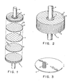
- FIGURE 1 a disk-shaped flywheel 1 is shown in exploded perspective emphasizing the layered construction and angular disposition between adjacent layers.
- the same flywheel is shown in FIGURE 2 in ordinary perspective.
- Circular layers 2 of glassy metal alloy strips 3 are built up, as discussed below, to produce a composite rotor 1 of desired thickness.
- Glassy metal alloy strips of indefinite length may be produced by any suitable continuous casting process, such as that described in Kavesh's patent below referenced. As extremely high quench rates are required to prevent crystallization in cooling a molten metal below its solidification temperature and eventually below its glass transition temperature; glassy metal alloys are necessarily produced in very thin shapes due to heat transfer considerations.
- a typical strip thickness is two mils.
- a typical width is 500 mils; however, considerable choice is available with respect to the width dimension.
- the aspect ratio of the strip cross section is 250, although strips with an aspect ratio down to about 5 may be readily produced. Further discussion of the aspect ratio is given below in connection with selecting bonding means for the invention. Therefore, it may be seen that construction of rigid articles by building up a number of such strips may be somewhat tedious owing to their small thickness.
- the strips 3 within a given layer are arranged in planar parallel fashion and joined edgewise longitudinally.
- strips are arranged and joined directly atop the previous adjacent layer at an angular disposition, preferably about 90°; with respect to the planar axes defined by the direction of the longitudinal axes of the strips.
- self-supporting units of two or more layers may be constructed in a similar manner, and then a number of such units may be joined to produce a desired thickness rotor.
- woven layers may be constructed from at least two sublayers of strips 3. To produce the circular shape of each layer; individual layers or units of a number of layers may be stamped.
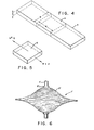
- FIGURES 4 and 5 the relationship between centrifugal tensile forces acting on individual strips 3 and bonding shear strength between strips is illustrated.
- Element 6 is within a strip 3 and has a length equal to the width of the strip.
- the strength of the strip is ⁇ ; the adhesive strength that is needed to restrain the strip until it reaches its fracture strength is T .
- T the adhesive strength that is needed to restrain the strip until it reaches its fracture strength.
- any type of adhesive is suitable that provides a bonding shear strength according to the above formulation and is compatible for joining glassy metal alloy substrates. Standard preparatory surface treatment of cleaning and etching may be done to take full advantage of the bonding properties of the adhesive.
- Commercially available epoxy adhesives are representative of satisfactory adhesives. For example, nylon-epoxy adhesives and epoxy-polyamide adhesives provide metal-to-metal bonding shear strengths of about 2000 psi to about 6000 psi.
- Bonding may also be accomplished by soldering or brazing provided the bonding shear strength of the join meets the above strength requirement and further provided the melting temperature of the solder or brazing material is less than the glass transition temperature for the particular glassy metal alloy, typically 750 to 950°F. If the glassy metal alloy were crystallized (and no longer glassy), then its extraordinary strength properties would be lost.
- Typical glassy metal alloys are described in U.S. Patent 3,856,513 "Novel Amorphous Metals and Amorphous Metal Articles” issued December 24; 1974, to H. S. Chen and D. E. Polk.
- An example of a typical method for producing glassy metal alloy strips is given in U.S. Patent 3,856,074 "Method of Centrifugal Production of Continuous Metal Filaments” issued December 24, 1974, to S. Kavesh.
- a discussion of the physical properties of glassy metal alloys, including isotropic high strength mechanical characteristics, is given in "Metallic Glasses - A New Technology" by J. J. Gilman, North Holland Publishing Company, 1977.
- the glassy metal alloy is preferably one having a high specific strength comparable to high strength anisotropic fibers, typically about 1 x 10 6 to 5 x 10 6 inches. Glassy metal alloys having a specific strength in the range of about 1 x 10 6 up to about 2.4 x 10 6 inches, and therefore being especially suited for the present invention, are shown in the following patents and are herein incorporated by reference.
- U.S. Patent 4;050;931 "Amorphous Metal Alloys in the Beryllium-Titanium-Zirconium System" issued September 27, 1977, and U.S. Patent 3;989;517 "Titanium-Beryllium Base Amorphous Alloys" issued November 2, 1976, both to L. Tanner et al.
- a typical alloy consists essentially of about 50 atom percent titanium, about 40 atom percent beryllium, and about 10 atom percent zirconium or boron and has a specific strength of about 2.4 x 10 6 inches.
- U.S. Patent 4,036,638 "Binary Amorphous Alloys of Iron or Cobalt and Boron" issued July 19, 1977, to R. Ray and S.
- Kavesh discloses iron-boron glassy metal alloys having a high specific strength of at least about 1.8 x 10 6 inches and consisting essentially of about 75 to 83 atom percent iron and about 25 to 17 atom percent boron, with the preferred alloy consisting essentially of about 75 atom percent iron and about 25 atom percent boron and having a specific strength of about 2.3 x 10 6 inches.
- flywheels may readily be produced either by building up a disk-shaped rotor and then selectively contouring the faces of the rotor or by selectively and symmetrically varying the radius of the individual layers as they are progressively added about the central layer or layers of the rotor.
- FIGURE 6 in which the reference numerals indicate generally the same elements as in the previous figures, a constant stress hyperbolic flywheel shape is shown.
- the hyperbolic shape symmetrical about the central layers of the rotor; produces a constant stress distribution throughout the rotor during operation eliminating relative high stress zones and thereby allowing increased rotational velocities. This shape is also referred to as an "optimized" shape.
- the flywheel is mounted on a shaft and rotatively interposed between a rotational energy source and a mechanical load driven by the source to serve as an energy storage buffer, charging or discharging depending upon mismatch between load demand and source output.
- hubs 5 may conveniently be employed to avoid placing the shaft through the center of the rotor to avoid stress concentration.
- the hubs may be joined to the rotor by bonding adhesively or by soldering or brazing as discussed above.
- the hub may be bolted to the rotor preferably by a number of bolts penetrating the rotor at an optimized radius based on stress considerations.
- the glassy metal alloy has magnetic properties.
- Magnetic hubs and a gripping powder, such as silicon carbide, may be employed to join the hubs to the rotor.
Landscapes
- Engineering & Computer Science (AREA)
- General Engineering & Computer Science (AREA)
- Physics & Mathematics (AREA)
- Acoustics & Sound (AREA)
- Aviation & Aerospace Engineering (AREA)
- Mechanical Engineering (AREA)
- Laminated Bodies (AREA)
- Manufacture Of Alloys Or Alloy Compounds (AREA)
Abstract
Description
- This invention relates generally to high performance energy storage flywheels. Specifically, this invention relates to composite flywheels constructed from glassy metal alloy strips and selected bonding means.
- Energy storage flywheels are rotatively interposed between a mechanical energy source and a mechanical load as a rotational energy storage device to reduce the peak capacity requirement of the energy source. When the load demand is less than the output of the energy source, the flywheel is charged with rotational energy, and conversely when load exceeds supply output, the flywheel is discharged of rotational energy.
- The amount of stored rotational energy or flywheel capacity increases with the square of angular velocity according to physical principles of kinetics; however, as a practical matter, the maximum angular velocity is limited by strength of materials considerations in order to preserve the structural integrity of the flywheel rotor. Further, efficiency considerations are important in evaluating a particular rotor. Efficiency of energy storage flywheels is expressed in terms of energy density (rotational energy/ rotor mass) and volumetric efficiency (rotational energy/ rotor volume). As efficiency increases, rotor space and mass requirements decrease for a given quantity of stored energy. Both the maximum allowable angular velocity and efficiency are directly related to the specific strength (tensile strength/density) of the primary load bearing material of the rotor. Therefore, increasing the specific strength of the primary load bearing material tends to increase both the energy storage capacity and efficiency of the flywheel.
- Flywheel rotors may be broadly classified with respect to materials of construction as isotropic or anisotropic. Isotropic rotors are constructed of a primary load bearing material having isotropic strength properties, i.e. substantially nondirectional strength properties. Anisotropic rotors are composite rotors utilizing a material, typically high strength fibers, having extremely high unidirectional specific strength in a bonding matrix for transverse support. Generally; composite rotors are made of a plurality of materials.
- Isotropic rotors of conventional materials, while being relatively easy to fabricate, have two major disadvantages. Their specific strength is not large enough to provide for high energy densities, and such rotors are subject to a catastrophic failure mode, rotor burst, whereby large, high energy fragments are cast off from the rotor during disintegration.
- Anisotropic rotors are superior to isotropic rotors as a result of the utilization of fibers having high unidirectional specific strength, thereby allowing increased energy densities. Typically, these rotors are built up of layers composed of these high strength fibers in a bonding matrix. By selectively varying orientation of these layers, and therefore of the fibers within the overall structure, a pseudoisotropic rotor is produced having a bulk specific strength less than that of the fibers but greater than that of conventional isotropic materials. Additionally, upon failure, these composite rotors disintegrate by the relatively benign failure mode of delamination; i.e. the rotor disintegrates by small bits since the matrix structure retards crack propagation. As a result, housing requirements are substantially reduced as compared to those for isotropic rotors.
- Examples of anisotropic flywheels and appropriate fibers are shown in U.S. Patents 3,788,162 "Pseudoisotropic Filament Disk Structures" issued January 29, 1974, to D. W. Rabenhorst et al. and 4,000,665 "Woven Filament Rotor Structure" issued January 4; 1977, also to D. W. Rabenhorst. The first cited patent shows a rotor composed of layers of high strength fibers arranged in parallel, planar fashion. Each layer is rotated within the structure with respect to adjacent layers so that a pseudoisotropic disk results. In the second cited patent, each layer of the disk is constructed by interweaving high strength fibers.
- However, there are limitations inherent with these anisotropic composite rotors. Full advantage is not taken of the high unidirectional strength of the composite fibers, due to multidirectional loading within a rotating flywheel. Additionally, the maximum packing factor obtainable for cylinders (fibers) is about 78%. Decreasing the packing factor increases volume and therefore decreases volumetric efficiency.
- The present invention overcomes these limitations by utilizing glassy metal alloy strips in combination with certain bonding means to construct layers from which a composite rotor is built up. Glassy metal alloys have high specific strength, comparable to high strength fibers, but in addition have isotropic or nondirectional strength characteristics, thereby providing the potential of rotors having a bulk strength approaching that of the glassy metal alloy as the primary load bearing material of the rotor.
- Additionally, glassy metal alloys may readily be produced in strip form. In building up a composite rotor from strips, as compared to fibers, nearly a 100% packing fraction can be obtained which tends to increase volumetric efficiency of the rotor. Also, strips, as opposed to fibers, provide greater relative adhesion due to the greatly increased surface area available for bonding to adjacent strips, allowing a wider range of selection for bonding materials in designing for a mechanically monolithic rotor. Despite the isotropic nature of the rotor, the primary failure mode is that of delamination and not rotor burst.
- The present invention provides a flywheel for energy storage having the capacity for storing rotational energy at high energy densities and at high volumetric efficiencies and having a delamination primary failure mode. The flywheel comprises a plurality of circular layers joined concentrically, each layer being composed of a plurality of glassy metal alloy strips joined in planar fashion, the strips having substantially equal thickness and aspect ratio (width/thickness), the aspect ratio being at least about 5. Bonding means provide a joining shear strength between the component layers and between the strips within each layer at least about equal to the tensile strength of the strip material divided by the aspect ratio.
- The glassy metal alloy strips within each layer may be arranged sequentially in planar parallel fashion and joined edgewise longitudinally or, alternatively, interlaced and joined in a woven pattern. The component layers may be mutually disposed such that the angles formed by the planar axes of adjacent layers are substantially equal throughout the flywheel structure. Additionally, the radii of the layers may be selectively varied in symmetrical fashion about the central layers in a substantially hyperbolic constant stress producing fashion.
- The particular glassy metal alloy material may be selected as one having a specific strength comparable to that of high strength anisotropic fibers. Bonding can be accomplished by adhesive bonding and also by soldering or brazing if carried out at a temperature less than the glass transition temperature of the particular glassy metal alloy.
- Further details are given below with reference to the examples shown in the drawings in which:
- FIGURE 1 is an exploded perspective view of a flywheel of the present invention, showing component layers of parallel glassy metal alloy strips and showing the angular disposition between adjacent layers.
- FIGURE 2 is a perspective view of the flywheel constituting a collapsed view of Figure 1.
- FIGURE 3 is a plan view.of a single layer of interlaced glassy metal alloy strips.
- FIGURES 4 and 5 show a schematic illustration of a small volume of strip material within a layer of the flywheel, illustrating the relationship between tensile stress induced by centrifugal forces and bonding shear stress at the strip faces in reaction to the tensile forces.
- FIGURE 6 is an elevation view of a layered flywheel having an "optimized" shape.
- Referring specifically to the drawings, in FIGURE 1 a disk-
shaped flywheel 1 is shown in exploded perspective emphasizing the layered construction and angular disposition between adjacent layers. The same flywheel is shown in FIGURE 2 in ordinary perspective. -
Circular layers 2 of glassymetal alloy strips 3 are built up, as discussed below, to produce acomposite rotor 1 of desired thickness. Glassy metal alloy strips of indefinite length may be produced by any suitable continuous casting process, such as that described in Kavesh's patent below referenced. As extremely high quench rates are required to prevent crystallization in cooling a molten metal below its solidification temperature and eventually below its glass transition temperature; glassy metal alloys are necessarily produced in very thin shapes due to heat transfer considerations. A typical strip thickness is two mils. A typical width is 500 mils; however, considerable choice is available with respect to the width dimension. For these dimensions, the aspect ratio of the strip cross section is 250, although strips with an aspect ratio down to about 5 may be readily produced. Further discussion of the aspect ratio is given below in connection with selecting bonding means for the invention. Therefore, it may be seen that construction of rigid articles by building up a number of such strips may be somewhat tedious owing to their small thickness. - In the embodiment shown in FIGURE 1, the
strips 3 within a given layer are arranged in planar parallel fashion and joined edgewise longitudinally. As a practical matter, to facilitate construction, strips are arranged and joined directly atop the previous adjacent layer at an angular disposition, preferably about 90°; with respect to the planar axes defined by the direction of the longitudinal axes of the strips. Alternatively, self-supporting units of two or more layers may be constructed in a similar manner, and then a number of such units may be joined to produce a desired thickness rotor. In an alternative, as shown in FIGURE 3, woven layers may be constructed from at least two sublayers ofstrips 3. To produce the circular shape of each layer; individual layers or units of a number of layers may be stamped. - In FIGURES 4 and 5, the relationship between centrifugal tensile forces acting on
individual strips 3 and bonding shear strength between strips is illustrated.Element 6 is within astrip 3 and has a length equal to the width of the strip. - Consider an
element 6 in such a structure that is subjected to a tensile stress and is restrained by shear forces provided by adhesion to its neighboring elements. Equating these forces and solving for the shear stress; the following expression is obtained: - o.w.t = τ.w2 or τ = α/R or τ = ρ (σ/ρ)/R where
- σ = tensile stress induced by centrifugal force.
- ρ = density of strip material.
- σ/ρ= specific strength.
- T = shear stress between adjacent bonded strips.
- w = strip width.
- t = strip thickness.
- R = w/t = aspect ratio of strip.
- Therefore, if the strength of the strip is σ; the adhesive strength that is needed to restrain the strip until it reaches its fracture strength is T. For example, if t = 0.002 inch and w = 0.50 inch then w/t = 250; and if σ = 500,000 psi, T would need to be 2000 psi, which is quite reasonable for an adhesive. This means that disks made as above could be spun to destruction of the ribbon but not the glue. Conversely, given a particular glassy metal alloy having a certain strength and after selecting an adhesive, the minimum required aspect ratio can be determined by the above formulation. For example, if the tensile strength of the glassy metal alloy is 600,000 psi and the selected adhesive has a metal-to-metal lap shear strength of 6000 psi, then the minimum aspect ratio for the strip is 100.
- Generally, any type of adhesive is suitable that provides a bonding shear strength according to the above formulation and is compatible for joining glassy metal alloy substrates. Standard preparatory surface treatment of cleaning and etching may be done to take full advantage of the bonding properties of the adhesive. Commercially available epoxy adhesives are representative of satisfactory adhesives. For example, nylon-epoxy adhesives and epoxy-polyamide adhesives provide metal-to-metal bonding shear strengths of about 2000 psi to about 6000 psi.
- Bonding may also be accomplished by soldering or brazing provided the bonding shear strength of the join meets the above strength requirement and further provided the melting temperature of the solder or brazing material is less than the glass transition temperature for the particular glassy metal alloy, typically 750 to 950°F. If the glassy metal alloy were crystallized (and no longer glassy), then its extraordinary strength properties would be lost.
- Typical glassy metal alloys are described in U.S. Patent 3,856,513 "Novel Amorphous Metals and Amorphous Metal Articles" issued December 24; 1974, to H. S. Chen and D. E. Polk. An example of a typical method for producing glassy metal alloy strips is given in U.S. Patent 3,856,074 "Method of Centrifugal Production of Continuous Metal Filaments" issued December 24, 1974, to S. Kavesh. A discussion of the physical properties of glassy metal alloys, including isotropic high strength mechanical characteristics, is given in "Metallic Glasses - A New Technology" by J. J. Gilman, North Holland Publishing Company, 1977.
- The glassy metal alloy is preferably one having a high specific strength comparable to high strength anisotropic fibers, typically about 1 x 10⁶ to 5 x 106 inches. Glassy metal alloys having a specific strength in the range of about 1 x 10 6 up to about 2.4 x 10 6 inches, and therefore being especially suited for the present invention, are shown in the following patents and are herein incorporated by reference.
U.S. Patent 4;050;931 "Amorphous Metal Alloys in the Beryllium-Titanium-Zirconium System" issued September 27, 1977, andU.S. Patent 3;989;517 "Titanium-Beryllium Base Amorphous Alloys" issued November 2, 1976, both to L. Tanner et al. disclose substantially amorphous (glassy) alloys of a titanium-beryllium base having a high specific strength of at least about 1.3 x 106 inches and being suitable for use in composite bodies. A typical alloy consists essentially of about 50 atom percent titanium, about 40 atom percent beryllium, and about 10 atom percent zirconium or boron and has a specific strength of about 2.4 x 106 inches. U.S. Patent 4,036,638 "Binary Amorphous Alloys of Iron or Cobalt and Boron" issued July 19, 1977, to R. Ray and S. Kavesh discloses iron-boron glassy metal alloys having a high specific strength of at least about 1.8 x 106 inches and consisting essentially of about 75 to 83 atom percent iron and about 25 to 17 atom percent boron, with the preferred alloy consisting essentially of about 75 atom percent iron and about 25 atom percent boron and having a specific strength of about 2.3 x 106 inches. - Other shapes of flywheels may readily be produced either by building up a disk-shaped rotor and then selectively contouring the faces of the rotor or by selectively and symmetrically varying the radius of the individual layers as they are progressively added about the central layer or layers of the rotor. For example in FIGURE 6, in which the reference numerals indicate generally the same elements as in the previous figures, a constant stress hyperbolic flywheel shape is shown. The hyperbolic shape; symmetrical about the central layers of the rotor; produces a constant stress distribution throughout the rotor during operation eliminating relative high stress zones and thereby allowing increased rotational velocities. This shape is also referred to as an "optimized" shape. The mathematical relationship providing the basis for the hyperbolic shape is presented in the two patents to Rabenhorst et al., above cited and herein incorporated by reference. There are also degrees of optimization.depending on the number or thickness of the central layers or how closely the hyperbolic shape is approximated depending upon practical production considerations.
- In use, the flywheel is mounted on a shaft and rotatively interposed between a rotational energy source and a mechanical load driven by the source to serve as an energy storage buffer, charging or discharging depending upon mismatch between load demand and source output.
- In mounting the flywheel rotor onto its
shaft 4;hubs 5 may conveniently be employed to avoid placing the shaft through the center of the rotor to avoid stress concentration. The hubs may be joined to the rotor by bonding adhesively or by soldering or brazing as discussed above. Also, the hub may be bolted to the rotor preferably by a number of bolts penetrating the rotor at an optimized radius based on stress considerations. A further alternative is provided in those applications where the glassy metal alloy has magnetic properties. Magnetic hubs and a gripping powder, such as silicon carbide, may be employed to join the hubs to the rotor. - While preferred embodiments of the invention have been illustrated and described, it will be recognized that the invention may be otherwise variously embodied and practiced within the scope of the following claims:
Claims (12)
Applications Claiming Priority (2)
| Application Number | Priority Date | Filing Date | Title |
|---|---|---|---|
| US05/946,481 US4186245A (en) | 1978-09-28 | 1978-09-28 | Energy storage flywheel |
| US946481 | 1997-10-07 |
Publications (2)
| Publication Number | Publication Date |
|---|---|
| EP0009902A1 true EP0009902A1 (en) | 1980-04-16 |
| EP0009902B1 EP0009902B1 (en) | 1982-12-08 |
Family
ID=25484533
Family Applications (1)
| Application Number | Title | Priority Date | Filing Date |
|---|---|---|---|
| EP79301902A Expired EP0009902B1 (en) | 1978-09-28 | 1979-09-14 | Energy storage flywheel |
Country Status (5)
| Country | Link |
|---|---|
| US (1) | US4186245A (en) |
| EP (1) | EP0009902B1 (en) |
| JP (1) | JPS5547033A (en) |
| CA (1) | CA1125544A (en) |
| DE (1) | DE2964215D1 (en) |
Cited By (1)
| Publication number | Priority date | Publication date | Assignee | Title |
|---|---|---|---|---|
| WO2024180152A1 (en) * | 2023-02-28 | 2024-09-06 | Levistor Ltd | Flywheel |
Families Citing this family (26)
| Publication number | Priority date | Publication date | Assignee | Title |
|---|---|---|---|---|
| US4537091A (en) * | 1980-09-24 | 1985-08-27 | The United States Of America As Represented By The United States Department Of Energy | Matched metal die compression molded structural random fiber sheet molding compound flywheel |
| DE3106607C2 (en) * | 1981-02-23 | 1987-08-20 | Fr. Kammerer GmbH, 7530 Pforzheim | Plating process |
| US4538079A (en) * | 1984-04-16 | 1985-08-27 | Mitsubishi Denki Kabushiki Kaisha | Flywheel device with compensation for non parallel plates |
| EP0202261B1 (en) * | 1984-11-19 | 1991-02-06 | Egger, Hans R. | Flywheel and method for making the same |
| US4860610A (en) * | 1984-12-21 | 1989-08-29 | E. I. Du Pont De Nemours And Company | Wound rotor element and centrifuge fabricated therefrom |
| US4817453A (en) * | 1985-12-06 | 1989-04-04 | E. I. Dupont De Nemours And Company | Fiber reinforced centrifuge rotor |
| US4701157A (en) * | 1986-08-19 | 1987-10-20 | E. I. Du Pont De Nemours And Company | Laminated arm composite centrifuge rotor |
| JP2825249B2 (en) * | 1987-04-07 | 1998-11-18 | アライドーシグナル・インコーポレーテッド | Multi-layer brazing foil |
| US5452625A (en) * | 1993-09-29 | 1995-09-26 | United Technologies Corporation | Energy storage flywheel device |
| US5760506A (en) * | 1995-06-07 | 1998-06-02 | The Boeing Company | Flywheels for energy storage |
| US6211589B1 (en) | 1995-06-07 | 2001-04-03 | The Boeing Company | Magnetic systems for energy storage flywheels |
| US6122993A (en) * | 1998-01-26 | 2000-09-26 | Alliedsignal Inc. | Isotropic energy storage flywheel rotor |
| JP3798320B2 (en) | 2000-05-02 | 2006-07-19 | ジョンズ ホプキンス ユニバーシティ | Method for producing reactive multilayer foil and resulting product |
| US6736942B2 (en) * | 2000-05-02 | 2004-05-18 | Johns Hopkins University | Freestanding reactive multilayer foils |
| US7361412B2 (en) | 2000-05-02 | 2008-04-22 | Johns Hopkins University | Nanostructured soldered or brazed joints made with reactive multilayer foils |
| JP4450080B2 (en) * | 2008-02-01 | 2010-04-14 | セイコーエプソン株式会社 | Watch gear and watch gear manufacturing method |
| US20100083790A1 (en) * | 2008-10-06 | 2010-04-08 | Graney Jon P | Flywheel device |
| US20100307286A1 (en) * | 2009-06-04 | 2010-12-09 | Teng-Hui Huang | Dual conic-shaped flying wheel |
| BR112013006120A2 (en) * | 2010-09-14 | 2016-05-31 | Power Tree Corp | composite steering wheel |
| US8584552B2 (en) | 2011-02-23 | 2013-11-19 | Mario H. Gottfried | High speed conical flywheel system |
| ES2688126T3 (en) * | 2013-03-07 | 2018-10-31 | Mario H. GOTTFRIED | High speed conical flywheel system |
| EP3020122B1 (en) | 2013-07-08 | 2020-11-18 | Saint-Augustin Canada Electric Inc. | Method for producing a kinetic energy storage system |
| US10050491B2 (en) | 2014-12-02 | 2018-08-14 | Management Services Group, Inc. | Devices and methods for increasing energy and/or power density in composite flywheel energy storage systems |
| CN110748603B (en) * | 2019-12-26 | 2020-04-10 | 沈阳微控新能源技术有限公司 | Flywheel with long fatigue life and flywheel energy storage system |
| CN113890264B (en) * | 2021-10-20 | 2023-02-03 | 哈尔滨工业大学 | Lunar soil filling type magnetic suspension flywheel energy storage device |
| IL289441B2 (en) * | 2021-12-27 | 2023-04-01 | Zooz Power Ltd | Flywheel assembly |
Citations (5)
| Publication number | Priority date | Publication date | Assignee | Title |
|---|---|---|---|---|
| US3788162A (en) * | 1972-05-31 | 1974-01-29 | Univ Johns Hopkins | Pseudo-isotropic filament disk structures |
| US4000665A (en) * | 1975-08-26 | 1977-01-04 | The Johns Hopkins University | Woven filament rotor structure |
| US4098142A (en) * | 1975-11-14 | 1978-07-04 | The United States Of America As Represented By The Administrator Of The National Aeronautics And Space Administration | Rotatable mass for a flywheel |
| US4102221A (en) * | 1976-07-19 | 1978-07-25 | General Electric Company | Cross-ply composite flywheel |
| FR2382623A1 (en) * | 1977-03-04 | 1978-09-29 | Lord Corp | MECHANICAL ENERGY ACCUMULATORS |
Family Cites Families (7)
| Publication number | Priority date | Publication date | Assignee | Title |
|---|---|---|---|---|
| US3764277A (en) * | 1969-08-28 | 1973-10-09 | R Hollis | Metal composites including layer of unwoven wires |
| US3856513A (en) * | 1972-12-26 | 1974-12-24 | Allied Chem | Novel amorphous metals and amorphous metal articles |
| US3856074A (en) * | 1973-04-06 | 1974-12-24 | Allied Chem | Method of centrifugal production of continuous metal filaments |
| US3989517A (en) * | 1974-10-30 | 1976-11-02 | Allied Chemical Corporation | Titanium-beryllium base amorphous alloys |
| US4050931A (en) * | 1975-08-13 | 1977-09-27 | Allied Chemical Corporation | Amorphous metal alloys in the beryllium-titanium-zirconium system |
| US4036638A (en) * | 1975-11-13 | 1977-07-19 | Allied Chemical Corporation | Binary amorphous alloys of iron or cobalt and boron |
| US4028962A (en) * | 1975-12-24 | 1977-06-14 | Nelson Edwin B | Design and construction of flywheels from anisotropic materials |
-
1978
- 1978-09-28 US US05/946,481 patent/US4186245A/en not_active Expired - Lifetime
-
1979
- 1979-09-14 DE DE7979301902T patent/DE2964215D1/en not_active Expired
- 1979-09-14 EP EP79301902A patent/EP0009902B1/en not_active Expired
- 1979-09-18 CA CA335,834A patent/CA1125544A/en not_active Expired
- 1979-09-26 JP JP12375079A patent/JPS5547033A/en active Pending
Patent Citations (5)
| Publication number | Priority date | Publication date | Assignee | Title |
|---|---|---|---|---|
| US3788162A (en) * | 1972-05-31 | 1974-01-29 | Univ Johns Hopkins | Pseudo-isotropic filament disk structures |
| US4000665A (en) * | 1975-08-26 | 1977-01-04 | The Johns Hopkins University | Woven filament rotor structure |
| US4098142A (en) * | 1975-11-14 | 1978-07-04 | The United States Of America As Represented By The Administrator Of The National Aeronautics And Space Administration | Rotatable mass for a flywheel |
| US4102221A (en) * | 1976-07-19 | 1978-07-25 | General Electric Company | Cross-ply composite flywheel |
| FR2382623A1 (en) * | 1977-03-04 | 1978-09-29 | Lord Corp | MECHANICAL ENERGY ACCUMULATORS |
Cited By (1)
| Publication number | Priority date | Publication date | Assignee | Title |
|---|---|---|---|---|
| WO2024180152A1 (en) * | 2023-02-28 | 2024-09-06 | Levistor Ltd | Flywheel |
Also Published As
| Publication number | Publication date |
|---|---|
| US4186245A (en) | 1980-01-29 |
| EP0009902B1 (en) | 1982-12-08 |
| JPS5547033A (en) | 1980-04-02 |
| CA1125544A (en) | 1982-06-15 |
| DE2964215D1 (en) | 1983-01-13 |
Similar Documents
| Publication | Publication Date | Title |
|---|---|---|
| US4186245A (en) | Energy storage flywheel | |
| US3788162A (en) | Pseudo-isotropic filament disk structures | |
| US4000665A (en) | Woven filament rotor structure | |
| US5590569A (en) | Energy storage flywheel device | |
| US3419952A (en) | Method for making composite material | |
| EP0870814B1 (en) | Cold accumulation material for ultra-low temperature, refrigerating machine using the material, and heat shield material | |
| US4356678A (en) | Composite structure | |
| AU594020B2 (en) | Method of making self-supporting ceramic materials | |
| US4639388A (en) | Ceramic-metal composites | |
| US3128544A (en) | Method of making a panel | |
| US3737694A (en) | Fanned circular filament rotor | |
| WO1992012566A1 (en) | Methods and apparatus for energy storage | |
| GB2198675A (en) | Method of forming diffusion bonded filament-reinforced articles | |
| US6122993A (en) | Isotropic energy storage flywheel rotor | |
| US3672241A (en) | Filament rotor structures | |
| US5840390A (en) | FRM disc preform and manufacturing method thereof | |
| JPH0474766A (en) | Diamond base sintered material | |
| US4900599A (en) | Filament reinforced article | |
| JPH10185339A (en) | Cryogenic cold storage material, refrigerating machine employing the same and heat shielding material | |
| US3353932A (en) | Composite material and method for making same | |
| JP2022101049A (en) | Flywheel solid disc rotor for flywheel power storage device | |
| CA1133206A (en) | Composite shell formed of glassy metal alloy strips | |
| JPS6146695B2 (en) | ||
| US4331497A (en) | Composite shell | |
| JPS62271333A (en) | Target of x-ray tube |
Legal Events
| Date | Code | Title | Description |
|---|---|---|---|
| PUAI | Public reference made under article 153(3) epc to a published international application that has entered the european phase |
Free format text: ORIGINAL CODE: 0009012 |
|
| AK | Designated contracting states |
Designated state(s): DE FR GB IT SE |
|
| 17P | Request for examination filed | ||
| RAP1 | Party data changed (applicant data changed or rights of an application transferred) |
Owner name: ALLIED CORPORATION |
|
| ITF | It: translation for a ep patent filed | ||
| GRAA | (expected) grant |
Free format text: ORIGINAL CODE: 0009210 |
|
| AK | Designated contracting states |
Designated state(s): DE FR GB IT SE |
|
| PG25 | Lapsed in a contracting state [announced via postgrant information from national office to epo] |
Ref country code: FR Free format text: THE PATENT HAS BEEN ANNULLED BY A DECISION OF A NATIONAL AUTHORITY Effective date: 19821208 |
|
| REF | Corresponds to: |
Ref document number: 2964215 Country of ref document: DE Date of ref document: 19830113 |
|
| PG25 | Lapsed in a contracting state [announced via postgrant information from national office to epo] |
Ref country code: SE Effective date: 19830915 |
|
| EN | Fr: translation not filed | ||
| GBPC | Gb: european patent ceased through non-payment of renewal fee | ||
| PG25 | Lapsed in a contracting state [announced via postgrant information from national office to epo] |
Ref country code: DE Effective date: 19840602 |
|
| PG25 | Lapsed in a contracting state [announced via postgrant information from national office to epo] |
Ref country code: GB Effective date: 19881118 |
|
| EUG | Se: european patent has lapsed |
Ref document number: 79301902.7 Effective date: 19850611 |
|
| PLBE | No opposition filed within time limit |
Free format text: ORIGINAL CODE: 0009261 |
|
| STAA | Information on the status of an ep patent application or granted ep patent |
Free format text: STATUS: NO OPPOSITION FILED WITHIN TIME LIMIT |