EP0009847A2 - Dry-shaver with a cutter for short hairs and a retractable cutter for long hairs - Google Patents
Dry-shaver with a cutter for short hairs and a retractable cutter for long hairs Download PDFInfo
- Publication number
- EP0009847A2 EP0009847A2 EP79200547A EP79200547A EP0009847A2 EP 0009847 A2 EP0009847 A2 EP 0009847A2 EP 79200547 A EP79200547 A EP 79200547A EP 79200547 A EP79200547 A EP 79200547A EP 0009847 A2 EP0009847 A2 EP 0009847A2
- Authority
- EP
- European Patent Office
- Prior art keywords
- slide
- switch
- dry
- slide switch
- switching
- Prior art date
- Legal status (The legal status is an assumption and is not a legal conclusion. Google has not performed a legal analysis and makes no representation as to the accuracy of the status listed.)
- Granted
Links
Images
Classifications
-
- B—PERFORMING OPERATIONS; TRANSPORTING
- B26—HAND CUTTING TOOLS; CUTTING; SEVERING
- B26B—HAND-HELD CUTTING TOOLS NOT OTHERWISE PROVIDED FOR
- B26B19/00—Clippers or shavers operating with a plurality of cutting edges, e.g. hair clippers, dry shavers
- B26B19/02—Clippers or shavers operating with a plurality of cutting edges, e.g. hair clippers, dry shavers of the reciprocating-cutter type
- B26B19/04—Cutting heads therefor; Cutters therefor; Securing equipment thereof
- B26B19/10—Cutting heads therefor; Cutters therefor; Securing equipment thereof involving two or more different types of reciprocating cutting elements, e.g. a pair of toothed shearing elements combined with a pair of perforated cutting elements or a combined toothed and perforated cutting assembly
- B26B19/102—Cutting heads therefor; Cutters therefor; Securing equipment thereof involving two or more different types of reciprocating cutting elements, e.g. a pair of toothed shearing elements combined with a pair of perforated cutting elements or a combined toothed and perforated cutting assembly with a secondary cutting unit being translated or slid into an operating position
Definitions
- the invention relates to a dry shaving apparatus with a short hair shear part, a long hair shear part arranged on a first slide switch and displaceable from a rest position into an operating position near the short hair shear part, which is coupled in the operating position to the drive of the dry shaving apparatus.
- Such dry shavers are currently on the market.
- the slide switch carrying the long-hair shear part is part of a double-function switch. It can first be moved out of its rest position into a first switch position in which the dry shaver is switched on. The dry shaver remains switched on if it is moved beyond the switch-on position.
- the long-hair shear part is shifted into the operating position and coupled to the drive of the dry shaving apparatus.
- This design of a dry shaver has the advantage that when the dry shaver is switched off, the long-hair shear part is always disengaged. As a result, the long-hair shear part need not run unnecessarily when the dry shaver is switched on and only the short-hair shear part is used. Since the long-hair shear part is relatively stiff, the dry shaver consumes a relatively large amount of electrical energy when it is switched on. In the case of battery-operated dry shavers, the unnecessary running of the long hair part leads to a relatively rapid depletion of the batteries. Apart from this, there is also unnecessary wear if the long-hair shear part runs along without it being needed.
- the invention has for its object to develop a dry shaver of the type mentioned, in which the long-hair shear part can remain in its optimal rest position when only the short-hair shear part is used, but in which it is still possible to switch on and off the dry shaver without changing hands and engage or disengage the long hair shear part.
- the first slide switch is assigned a second slide switch which is displaceable relative to the first slide switch for switching the dry shaving apparatus on and off.
- the slide switch with the long-hair shear part need not be moved, so that the long-hair shear part can remain in its optimal rest position and therefore does not interfere with the use of the short-hair shear part.
- the slide switch for switching on and off is directly assigned to the slide switch with the long-hair shear part, the long-hair shear part can be switched on if necessary without the user having to change his grip.
- An advantageous embodiment of the invention is that the second slide switch for switching the dry shaving apparatus on and off is arranged on the first slide switch.
- the first slide switch must be of considerable size, since it is not only a slide switch but also a holder for the long-hair shear part. Therefore, the slide switch can be easily placed on it for switching on and off.
- this embodiment of the invention is particularly favorable, since the housing of thekowskira- siera p parates it need not be formed at different positions according to the requirements of the second switch slide.
- Another favorable embodiment of the invention is that the second slide switch for switching the dry shaving apparatus on and off can be moved transversely to the first slide switch.
- each slide switch can be actuated independently of the others, but both slide switches can be actuated by, for example, placing the thumb on the second slide switch. This makes switching extremely easy. In addition, it can be seen at a glance whether the long-hair shear part is in the operating position or in the rest position, so that it can no longer be expected that the long-hair shear part will always remain switched on for convenience or forgetfulness.
- the second slide switch for switching the dry shaving apparatus on and off can be moved in the same direction as the first switch slide.
- the second slide valve can be designed so that after reaching the switch-on position it takes the first slide valve with it, so that when the second slide valve is moved, only the slide valve is moved relative to the first slide valve, but with a larger displacement the first slide valve together with the second slide switch is moved.
- the second Switch slide moved beyond the switch-off position so that the first switch slide with the long-hair shear part can return to its rest position.
- the first slide switch with the long-hair shear part is held in its two end positions by resilient means.
- the manually required displacement path of the first slide switch becomes smaller because after it has overcome its dead center it automatically reaches its end position. This ensures that in the operating position the long-hair shear part is completely coupled to the drive of the dry shaving apparatus, since the first switch slide always reaches its end position fully due to its S.
- Another favorable embodiment of the invention consists in that the second slide switch can be moved between two stops of the first slide switch in the insertion and removal of the dry shaving apparatus. As long as the dry shaver is only switched on or off, the position of the first slide switch and thus the position of the long-hair shear part does not change. However, if the second slide switch is moved beyond the display or exhibition, it inevitably takes the slide switch with it via stops, so that the long-hair shear part can be moved either in the operating position or in the rest position.
- the first slide switch is biased by compression springs in the direction of its rest position. This configuration means that when the drying razor is switched off, the first slide switch and thus also the long-hair shear part are inevitably pushed back into its rest position. The long-hair shear part cannot run if it has not been pushed back into the rest position after use for convenience or forgetfulness.
- the compression springs can either be arranged in the shaving head frame or in the housing of the dry shaving apparatus.
- the second slide switch has latching devices for latching in the on and off and in the operating position of the long-hair shear part. By means of these catches, the second slide valve can hold the first slide valve in the operating position, so that the compression springs cannot automatically push it back into the rest position.
- the second slide switch is designed as a shift gate with a plunger actuating an electrical switch, and this shift gate is inserted into a recess in the first shift slide.
- a further very advantageous embodiment of the invention is characterized in that the first slide switch has two locking points which define the setting and setting of the second slide switch, into which the second slide switch or the shifting gate can be snapped in with a catch, and in the housing of the 'dry shaving apparatus a Stop edge is provided, by means of which the catch is prevented from disengaging from the switch-on catch, as long as the first slide switch hzw, the shift gate is above its rest position.
- the invention allows numerous Ausfilhrungs possibilities. Several of these are shown very schematically in the drawing and are described below.
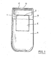
- Fig. 1 shows a dry shaver, which consists essentially of a housing A and a shaving head frame B with the shaving parts of the short hair part, namely shaving foil C and knife block D.
- a long-hair shear part 2 is attached to the housing A on a slide switch 1 described in more detail below.
- a second slide switch Arranged in the dash-dotted field E is a second slide switch, which, as indicated in the following, can have different embodiments.
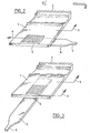
- FIG. 2 shows in detail a first embodiment of the slide switch 1, which carries the long-hair shear part 2.
- the slide switch 1 By moving this slide switch 1 in the direction of arrow 3, the long-hair shear part 2 is shifted out of a rest position into an operating position in which it is coupled to the drive of the dry shaving apparatus and thereby moves with it.
- a second slide valve 5 is arranged transversely to it in the direction of arrow 4. This is rigidly connected to a switching gate 6, which is in the assembled state of the parts shown in Fig. 1 within the housing A of the dry shaver.
- the switching gate 6 has a plunger 7, with which an electrical switch (not shown) is actuated in the exhibition of the slide switch 5.
- the slide switch 5 is first shifted towards the left in the direction of part 4 in the drawing.
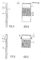
- first slide switch 1 on which a long-hair shear part 2 is attached.
- the slide switch 1 has on its outside a recessed surface 11 on which the second slide switch 5 is arranged. It is not shown how the second slide switch 5 reaches through the first slide switch in order to be able to actuate an electrical switch with a plunger or the like.
- the recessed surface 11 creates a stop 12 against which the slide switch 5 can be moved after it has reached the switched-on position of the dry shaving apparatus.
- the upper limit of the elongated hole 14 seen in the drawing is capable of moving the second slide switch 5 against the pin downward 13 to arrive and thereby to move the first slide switch 1.
- the length of the elongated hole 14 and the distance between the second slide switch 5 and the stop 12 must be dimensioned such that the second slide switch 5 can be moved freely from its switched-off position to its switched-on position without displacement of the first slide switch 1.
- FIGS. 4 and 5 it is possible to switch the dry shaving apparatus on and off without pushing the long-hair shear part 2 back into its rest position.
- two compression springs 17, 18 are arranged in the embodiment according to FIGS. 6 and 7 in the shaving head frame B, which bias the first slide switch 1 in the direction of its rest position.
- the second switch slide 5 is not arranged on the first switch slide 1 but rather below the first switch slide 1 on the housing A of the dry shaving apparatus.
- a game 19 is provided between the first slide switch 1 and the second slide switch 5, after overcoming which the second slide switch 5 takes the first slide switch 1 with it. This game is so large that the second slide can be moved from the off position to the on position without actuating the first slide valve.
- locking devices which hold the slide switch 1 in its upper position so that it cannot return automatically to its rest position.
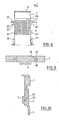
- FIG. 8 differs from that according to FIGS. 6 and 7 initially in that the compression springs 17, 18 are arranged at the lower end of the first slide switch 1 and thus in the housing of the dry shaving apparatus.
- two latching devices 2 0 , 21 and 20 ', 21' are shown on each side of the second slide switch 5.
- the first latching device has two latching points 22, 23 lying close together, by means of which the insertion and removal of the second slide switch 5 is fixed.
- the second pasting devices 21, 21 ' are at such a distance from the first latching devices 2 0 , 2 0 ' that they determine the operating position of the first slide switch 1 and thus of the long-hair shear part 2.
- the holding force of the latching device 21, 21 ' must be so great that the compression springs 17, 18 do not automatically move the first slide switch 1 back into its rest position.
- the first slide switch 1 is pushed up in that the second slide valve 5, after overcoming a game, comes up against a stop 24 of the first slide valve 1.
- the embodiment according to FIG. 9 is made in such a way that, despite the arrangement of two slide switches, a unitary component is created which is as flat as possible.
- the second slide switch 5 is also a shift gate.
- the first slide switch has a recess 25 with longitudinal grooves 26 into which the second slide switch 5 engages with projections 27.
- the second slide switch can be displaced in the grooves 26 relative to the first slide switch with its projections 27, as in the previously described embodiments.
- the Fir. 10 shows that the first slide switch 1 can also be offset from the inside of the dry shaving apparatus, so that the switching link 6 does not protrude beyond the thickness of the first slide switch.
- the switching gate 6 is connected via a pin 28 to the second slide switch 5 on the outside of the first slide switch 1. This pin 28 is guided through an elongated hole 29 of the first slide switch.
- the first switch slide has two closely arranged side by side latching points 3 0, 31.
- the shift gate 6 engages with an electrode disposed on an arm 32 latch 33 in the latch stop 31, which defines the open position of the dry shaving.
- the catch 33 remains in the locking point 3o and thereby takes the first slide switch 1 upward, so that the shaving head part comes into the operating position.
- the detent 33 takes the first slide switch with the shaving head part when the shifting gate 6 is pushed back into its rest position before it disengages from the detent point 3o and returns to the detent point 31 and thereby switches off the dry shaving apparatus.
- a strip 34 is arranged fixed to the housing, the connection edge 35 of which facing the arm runs so closely parallel to the arm 32 above the latching point 30 that this is not able to move radially outward from the locking point 3o.
Landscapes
- Life Sciences & Earth Sciences (AREA)
- Forests & Forestry (AREA)
- Engineering & Computer Science (AREA)
- Mechanical Engineering (AREA)
- Dry Shavers And Clippers (AREA)
Abstract
Bei einem Trockenrasierapparat mit einem Kurzhaarscherteil (C, D), einem auf einem ersten Schaltschieber (1) angeordneten, aus einer Ruhestellung in eine Betriebsstellung nahe des Kurzhaarscherteils (C, D) verschiebbaren Langhaarscherteil (2), welcher in der Betriebsstellung mit dem Antrieb des Trockenrasierapparates gekuppelt ist, ist dem ersten Schaltschieber (1) unmittelbar ein zweiter, relativ zu dem ersten Schaltschieber (1) verschiebbarer Schaltschieber (E) zum Ein- und Ausschalten des Trockenrasierapparates zugeordnet.In a dry shaving apparatus with a short-hair shear part (C, D), a long-hair shear part (2) arranged on a first slide switch (1) and displaceable from a rest position into an operating position near the short-hair shear part (C, D), which in the operating position is driven by the When the dry shaving apparatus is coupled, the first switching slide (1) is directly assigned a second switching slide (E) which can be displaced relative to the first switching slide (1) for switching the dry shaving apparatus on and off.
Description
Die Erfindung bezieht sich auf einen Trockenrasierapparat mit einem Kurzhaarscherteil, einen auf einem ersten Schaltschieber angeordneten, aus einer Ruhestellung in eine Betriebsstellung nahe des Kurzhaarscherteiles verschiebbaren Langhaarscherteil, welcher in der Betriebsstellung Mit dem Antrieb des Trockenrasierapparates gekuppelt ist.The invention relates to a dry shaving apparatus with a short hair shear part, a long hair shear part arranged on a first slide switch and displaceable from a rest position into an operating position near the short hair shear part, which is coupled in the operating position to the drive of the dry shaving apparatus.
Solche Trockenrasierapparate sind derzeit auf dem Markt. Bei diesen bekannten Trockenrasierapparaten ist der das Langhaarscherteil tragende Schaltschieber Teil eines Doppelfunktionsschalters. Er läßt sich zunächst aus seiner Ruhestellung heraus in eine erste Schaltstellung verschieben, in der der Trockenrasierapparat eingeschaltet ist. Bei weiterer Verschiebung über die Einschaltstellung hinaus bleibt der Trockenrasierapparat eingeschaltet. Das Langhaarscherteil wird jedoch in Betriebsstellung verschoben und mit dem Antrieb des Trockenrasierapparates gekuppelt.Such dry shavers are currently on the market. In these known dry shavers, the slide switch carrying the long-hair shear part is part of a double-function switch. It can first be moved out of its rest position into a first switch position in which the dry shaver is switched on. The dry shaver remains switched on if it is moved beyond the switch-on position. However, the long-hair shear part is shifted into the operating position and coupled to the drive of the dry shaving apparatus.
Diese Gestalung eines Trockenrasierapparates bringt den Vorteil mit sich, daß beim Ausschalten des Trockenrasierapparates stets das Langhaarscherteil ausgekuppelt wird. Dadurch braucht das Langhaarscherteil nicht unnötig mitzulaufen, wenn der Trockenrasierapparat eingeschaltet und nur das Kurzhaarscherteil benutzt wird. Da das Langhaarscherteil relativ schwergängig ist, verbraucht der Trockenrasierapparat relativ viel elektrische Energie, wenn es zugeschaltet ist. Bei batteriebetriebenen Trockenrasierapparaten führt das unnötige Mitlaufen des Langhaarscherteiles zu einem verhältnismäßig raschen Erschöpfen der Batterien. Hiervon abgesehenergibt sich auch ein unnötiger Verschleiß, wenn das Langhaarscherteil mitläuft, ohne daß es benötigt wird.This design of a dry shaver has the advantage that when the dry shaver is switched off, the long-hair shear part is always disengaged. As a result, the long-hair shear part need not run unnecessarily when the dry shaver is switched on and only the short-hair shear part is used. Since the long-hair shear part is relatively stiff, the dry shaver consumes a relatively large amount of electrical energy when it is switched on. In the case of battery-operated dry shavers, the unnecessary running of the long hair part leads to a relatively rapid depletion of the batteries. Apart from this, there is also unnecessary wear if the long-hair shear part runs along without it being needed.
Während der vorbekannte Trockenrasierapparat die Aufgabe der Vermeidung des unnötigen Mitlaufens des Langhaarscherteils auf vollkommene Weise löst, ist eine andere für die Benutzung des Gerätes wichtige Aufgabe nur teilweise gelöst. Um mit dem Kurzhaarscherteil auch schwer zugängliche Gesichtszonen bequem erreichen zu können, soll sich das Langhaarscherteil in-einer Ruhestellung befinden, solange es nicht benutzt wird, und in der es bei Benutzung des Kurzhaarscherteiles nicht stört. Beim Einschalten des Trockenrasierapparates wird jedoch der Schaltschieber mit dem Langhaarscherteil aus seiner Ruhestellung in Richtung des Scherkopfes verschoben. Das Langhaarscherteil nähert sich dadurch zwangsläufig dem Kurzhaarscherteil und kann bei dessen Benutzung stören.While the previously known dry shaver completely solves the task of avoiding the unnecessary running of the long-hair shear part, another task that is important for the use of the device is only partially achieved. In order to be able to easily reach difficult-to-access facial areas with the short hair clipper part, that should be Long hair trimmer is in a rest position as long as it is not in use and in which it does not interfere when using the short hair trimmer. When the dry shaver is switched on, however, the slide switch with the long-hair shear part is moved from its rest position in the direction of the shaving head. The long-hair shear part inevitably approaches the short-hair shear part and can interfere with its use.
Der Erfindung liegt die Aufgabe zugrunde, einen Trockenrasierapparat der eingangs genannten Art zu entwickeln, bei dem das Langhaarscherteil in seiner optimalen Ruhestellung verbleiben kann, wenn nur das Kurzhaarscherteil benutzt wird, bei dem es aber dennoch möglich ist, ohne umzugreifen den Trockenrasierapparat ein- und auszuschalten und das Langhaarscherteil ein- oder auszukuppeln.The invention has for its object to develop a dry shaver of the type mentioned, in which the long-hair shear part can remain in its optimal rest position when only the short-hair shear part is used, but in which it is still possible to switch on and off the dry shaver without changing hands and engage or disengage the long hair shear part.
Diese Aufgabe wird erfindungsgemäß dadurch gelöst, daß dem ersten Schaltschieber unmittelbar ein zweiter relativ zu dem ersten Schaltschieber verschiebbarer Schaltschieber zum Ein- und Ausschalten des Trockenrasierapparates zugeordnet ist.This object is achieved in that the first slide switch is assigned a second slide switch which is displaceable relative to the first slide switch for switching the dry shaving apparatus on and off.
Durch diese Ausgestaltung braucht beim Ein- und Ausschalten des Trockenrasierapparates der Schaltschieber mit dem Langhaarscherteil nicht verschoben zu werden, so daß das Langhaarscherteil in seiner optimalen Ruhestellung verbleiben kann und deshalb bei Benutzung des Kurzhaarscherteiles nhht stört. Da der Schaltschieber zum Ein- und Ausschalten jedoch unmittelbar dem Schaltschieber mit dem Langhaarscherteil zugeordnet ist, kann bei Bedarf das Langhaarscherteil zugeschaltet werden, ohne daß der Benutzer hierzu umgreifen muß.With this configuration, when the dry shaving apparatus is switched on and off, the slide switch with the long-hair shear part need not be moved, so that the long-hair shear part can remain in its optimal rest position and therefore does not interfere with the use of the short-hair shear part. However, since the slide switch for switching on and off is directly assigned to the slide switch with the long-hair shear part, the long-hair shear part can be switched on if necessary without the user having to change his grip.
Eine vorteilhafte Ausgestaltung der Erfindung besteht darin, daß der zweite Schaltschieber zum Ein- und Ausschalten des Trockenrasierapparates auf dem ersten Schaltschieber angeordnet ist.An advantageous embodiment of the invention is that the second slide switch for switching the dry shaving apparatus on and off is arranged on the first slide switch.
Der erste Schaltschieber muß beträchtliche Größe haben, da er nicht nur Schaltschieber sondern zugleich Halterung für das Langhaarscherteil ist. Deshalb kann der Schaltschieber zum Ein- und Ausschalten gut auf ihm Platz finden. Fertigungstechnisch ist diese Ausgestaltung der Erfindung besonders günstig, da das Gehäuse des Trockenra- sierapparates dabei nicht an verschiedenen Stellen entsprechend den Erfordernissen des zweiten Schaltschiebers ausgebildet sein muß.The first slide switch must be of considerable size, since it is not only a slide switch but also a holder for the long-hair shear part. Therefore, the slide switch can be easily placed on it for switching on and off. Production engineering, this embodiment of the invention is particularly favorable, since the housing of the Trockenra- siera p parates it need not be formed at different positions according to the requirements of the second switch slide.
Eine andere günstige Ausgestaltung der Erfindung besteht darin, daß der zweite Schaltschieber zum Ein- und Ausschalten des Trockenrasierapparates quer zum ersten Schaltschieber verschiebbar ist.Another favorable embodiment of the invention is that the second slide switch for switching the dry shaving apparatus on and off can be moved transversely to the first slide switch.
Bei dieser Ausgestaltung ist zwar jeder Schaltschieber unabhängig von anderen betätigbar, jedoch können beide Schaltschieber dadurch betätigt werden, daß zum Beispiel der Daumen auf den zweiten Schaltschieber gelegt wird. Dadurch ist das Schalten äußerst bequem durchzuführen. Obendrein ist mit einem Blick zu erkennen, ob sich das Langhaarscherteil in Betriebsstellung oder Ruhestellung befindet, so daß nicht mehr damit zu rechnen ist, daß das Langhaarscherteil aus Bequemlichkeit oder Vergeßlichkeit stets eingeschaltet bleibt.In this embodiment, each slide switch can be actuated independently of the others, but both slide switches can be actuated by, for example, placing the thumb on the second slide switch. This makes switching extremely easy. In addition, it can be seen at a glance whether the long-hair shear part is in the operating position or in the rest position, so that it can no longer be expected that the long-hair shear part will always remain switched on for convenience or forgetfulness.
Eine weitere vorteilhafte Ausgestaltung der Erfindung besteht darin, daß der zweite Schaltschieber zum Ein- und Ausschalten des Trockenrasierapparates in gleicher Richtung wie der erste Schaltschieber verschiebbar ist. Der zweite Schaltschieber kann dabei so gestaltet sein, daß er nach Erreichen der Einschaltstellung bei weiterer Verschiebung den ersten Schaltschieber mitnimmt, so daß durch Verschieben des zweiten Schaltschiebers zunächst nur dieser selbst relativ zum ersten Schaltschieber, bei einem größeren Verschiebeweg jedoch der erste Schaltschieber zusammen mit dem zweiten Schaltschieber verschoben wird. In umgekehrter Richtung wird der zweite Schaltschieber über die Ausschaltstellung hinaus verschoben, so daß der erste Schaltschieber mit dem Langhaarscherteil wieder zurück in seine Ruhestellung gelangen kann. Durch diesen Funktionsaublauf ist die erfindungsperäße Anordnung beouem zu handhaben. Sie ist auch deshalb vorteilhaft, weil sich bei ihr die Schaltkulisse in Längsrichtung, also in Schaltrichtung und nicht quer dazu verschiebt. Aus diesem Grunde ist die Schaltkulisse leichter im Gehäuse des Trockenrasierapparates unterzubringen.Another advantageous embodiment of the invention is that the second slide switch for switching the dry shaving apparatus on and off can be moved in the same direction as the first switch slide. The second slide valve can be designed so that after reaching the switch-on position it takes the first slide valve with it, so that when the second slide valve is moved, only the slide valve is moved relative to the first slide valve, but with a larger displacement the first slide valve together with the second slide switch is moved. In the opposite direction, the second Switch slide moved beyond the switch-off position so that the first switch slide with the long-hair shear part can return to its rest position. This functional sequence makes it possible to handle the arrangement according to the invention with ease. It is also advantageous because the shifting link moves in the longitudinal direction, i.e. in the shifting direction and not transversely to it. For this reason, the switching gate is easier to accommodate in the housing of the dry shaver.
Günstig ist es auch, wenn gemäß einer anderen Ausgestaltung der Erfindung der erste Schaltschieber mit dem Langhaarscherteil durch federnde Mittel in seinen beiden Endstellungen gehalten ist. Hierdurch erhält der Schaltschieber eine Sprungcharakteristik. Der manuell erforderliche Verschiebeweg des ersten Schaltschiebers wird kleiner, da er nach Überwindung seines Totpunktes von selbst in seine jeweilige Endstellung gelangt. Es ist dadurch sichergestellt, daß in der Betriebsstellung das Langhaarscherteil vollständig mit dem Antrieb des Trockenrasierapparates gekuppelt ist, da der erste Schaltschieber durch seine S.Drungcharakteristik stets voll in seine Endstellung gelangt.It is also advantageous if, according to another embodiment of the invention, the first slide switch with the long-hair shear part is held in its two end positions by resilient means. This gives the slide switch a jump characteristic. The manually required displacement path of the first slide switch becomes smaller because after it has overcome its dead center it automatically reaches its end position. This ensures that in the operating position the long-hair shear part is completely coupled to the drive of the dry shaving apparatus, since the first switch slide always reaches its end position fully due to its S.
Eine andere günstige Ausgestaltung der Erfindung besteht darin, daß der zweite Schaltschieber zwischen zwei Anschlägen des ersten Schaltschiebers in Ein- und Ausstellung des Trockenrasierapparates verschiebbar ist. Solange der Trockenrasierapparat nur ein- oder ausgeschaltet wird, verändert sich die Lage des ersten Schaltschiebers und damit die Lage des Langhaarscherteiles nicht. Wird der zweite Schaltschieber jedoch über die Ein- oder Ausstellung hinaus verschoben, so nimmt er über Anschläge den Schaltschieber zwangsläufig mit, so daß das Langhaarscherteil entweder in Betriebs- oder in Ruhestellung verschiebbar ist.Another favorable embodiment of the invention consists in that the second slide switch can be moved between two stops of the first slide switch in the insertion and removal of the dry shaving apparatus. As long as the dry shaver is only switched on or off, the position of the first slide switch and thus the position of the long-hair shear part does not change. However, if the second slide switch is moved beyond the display or exhibition, it inevitably takes the slide switch with it via stops, so that the long-hair shear part can be moved either in the operating position or in the rest position.
Eine weitere vorteilhafte Ausgestaltung der Erfindung besteht darin, daß der erste Schaltschieber durch Druckfedern in Richtung seiner Ruhestellung vorgespannt ist. Durch diese Ausgestaltung wird bei Ausschalten des Trokkenrasierapparates der erste Schaltschieber und damit auch das Langhaarscherteil zwangsläufig zurück in seine Ruhestellung geschoben. Das Langhaarscherteil kann nicht mitlaufen, wenn es aus Bequemlichkeit oder Vergeßlichkeit nicht nach Benutzung in die Ruhestellung zurückgeschoben wurde.Another advantageous embodiment of the invention is that the first slide switch is biased by compression springs in the direction of its rest position. This configuration means that when the drying razor is switched off, the first slide switch and thus also the long-hair shear part are inevitably pushed back into its rest position. The long-hair shear part cannot run if it has not been pushed back into the rest position after use for convenience or forgetfulness.
Die Druckfedern können entweder im Scherkopfrahmen oder im Gehäuse des Trockenrasierapparates angeordnet sein.The compression springs can either be arranged in the shaving head frame or in the housing of the dry shaving apparatus.
Günstig ist es auch, wenn der zweite Schaltschieber Rasteinrichtungen zum Einrasten in der Ein-'und Ausstellung und in der Betriebsstellung des Langhaarscherteiles hat. Durch diese Rasten vermag der zweite Schaltschieber den ersten Schaltschieber in Betriebsstellung festzuhalten, so daß die Druckfedern ihn nicht selbsttätig zurück in Ruhestellung schieben können.It is also favorable if the second slide switch has latching devices for latching in the on and off and in the operating position of the long-hair shear part. By means of these catches, the second slide valve can hold the first slide valve in the operating position, so that the compression springs cannot automatically push it back into the rest position.
Gemäß einer anderen vorteilhaften Ausgestaltung der Erfindung ist der zweite Schaltschieber als Schaltkulisse mit einem einen elektrischen Schalter betätigenden Stößel ausgebildet und diese Schaltkulisse ist in eine Ausnehmung des ersten Schaltschiebers eingesetzt. Durch diese Ausgestaltung führt die Anordnung von zwei Schaltschiebern nicht dazu, daß dadurch ein relativ dickes Bauteil entsteht, welche im bzw. auf dem Gehäuse des Trockenrasierapparates schwierig und optisch unschön unterzubringen wäre.According to another advantageous embodiment of the invention, the second slide switch is designed as a shift gate with a plunger actuating an electrical switch, and this shift gate is inserted into a recess in the first shift slide. This configuration means that the arrangement of two slide switches does not result in a relatively thick component which would be difficult and visually unattractive to accommodate in or on the housing of the dry shaving apparatus.
Eine weitere sehr vorteilhafte Ausgestaltung der Erfindung zeichnet sich dadurch aus, daß der erste Schaltschieber zwei die Aus- und Einstellung des zweiten Schaltschiebers festlegende Raststellen hat, in welche der zweite Schaltschieber bzw. die Schaltkulisse mit einer Raste einrastbar ist und daß im Gehäuse des'Trockenrasierapparates eine Anschlagkante vorgesehen ist, durch welche ein Ausrasten der Raste aus der Einschaltraste verhindert ist, solange sich der erste Schaltschieber hzw, die Schaltkulisse oberhalb ihrer Ruhestellung befindet.A further very advantageous embodiment of the invention is characterized in that the first slide switch has two locking points which define the setting and setting of the second slide switch, into which the second slide switch or the shifting gate can be snapped in with a catch, and in the housing of the 'dry shaving apparatus a Stop edge is provided, by means of which the catch is prevented from disengaging from the switch-on catch, as long as the first slide switch hzw, the shift gate is above its rest position.
Die Erfindung läßt zahlreiche Ausfilhrungsmöglichkeiten zu. Mehrere davon sind in der Zeichnung stark schematisch dargestellt und werden nachfolgend beschrieben.The invention allows numerous Ausfilhrungs possibilities. Several of these are shown very schematically in the drawing and are described below.
Es zeigen:
- Fig. 1 die Ansicht eines Trockenrasierapparates mit einem Kurzhaarscherteil und einem Langhaarscherteil,
- Fig. 2 eine perspektivische Ansicht einer ersten Ausführungsform der erfindungsgemäß ausgebildeten Schaltschieber eines Trockenrasierapparates,
- Fig. 3 eine perspektivische Ansicht einer zweiten Ausführungsform der erfindungsgemäß ausgebildeten Schaltschieber eines Trockenrasierapparates,
- Fig. 4 einen Längsschnitt durch eine dritte Ausführungsform der erfindungsgeräß ausgebildeten Schaltschieber,
- Fig. 5 eine Draufsicht auf die Anordnung gemäß Fig. 3,
- Fig. 6 einen Längsschnitt durch eine vierte Ausffihrungsform der erfindungsgemäß ausgebildeten Schaltschieber,
- Fig. 7 eine Draufsicht auf die Anordnung gemäß Fig. 5,
- Fig. 8 eine Draufsicht auf eine fünfte Ausführungsform der erfindungsgemäß ausgestalteten Schaltschieber,
- Fig. 9 einen Querschnitt durch eine sechste Ausführungsform der erfindungsgemäß gestalteten Schaltschieber,#
- Fig.10 einen Längsschnitt durch eine siebte Ausführungsform der erfindungsgemäß gestalteten Schaltschieber,
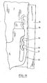
- Fig.11 eine optimale Art der Verrastung zweier Schaltschieber im Inneren eines Trockenrasierapparates.
- 1 is a view of a dry shaver with a short hair part and a long hair part,
- 2 is a perspective view of a first embodiment of the slide switch of a dry shaving apparatus designed according to the invention,
- 3 is a perspective view of a second embodiment of the slide switch of a dry shaving apparatus designed according to the invention,
- 4 shows a longitudinal section through a third embodiment of the slide switch designed according to the invention,
- 5 is a plan view of the arrangement of FIG. 3,
- 6 shows a longitudinal section through a fourth embodiment of the slide switch designed according to the invention,
- 7 is a plan view of the arrangement of FIG. 5,
- 8 is a plan view of a fifth embodiment of the slide switch designed according to the invention,
- 9 shows a cross section through a sixth embodiment of the slide switch designed according to the invention,
- 10 shows a longitudinal section through a seventh embodiment of the slide switch designed according to the invention,
- Fig.11 an optimal way of locking two switch slides inside a dry shaver.
Fig. 1 zeigt einen Trockenrasierapparat, der im wesentlichen aus einem Gehäuse A und einem Scherkopfrahmen B mit den Scherteilen des Kurzhaarscherteiles, nämlich Scherfolie C und Messerblock D, besteht. Auf dem Gehäuse A ist auf einem nachstehend näher beschriebenen Schaltschieber 1 ein Langhaarscherteil 2 angebracht. In dem strichpunktiert umrandeten Feld E ist ein zweiter Schaltschieber angeordnet, der, wie in folgenden angegeben, verschiedene Ausführungsformen haben kann.Fig. 1 shows a dry shaver, which consists essentially of a housing A and a shaving head frame B with the shaving parts of the short hair part, namely shaving foil C and knife block D. A long-
Die Fig. 2 zeigt im Detail eine erste Ausbildungsform des Schaltschiebers 1, welcher das Langhaarscherteil 2 trägt. Durch Verschieben dieses Schaltschiebers 1 in Richtung des Pfeiles 3 wird das Langhaarscherteil 2 aus einer Ruhestellung heraus in eine Eetriebsstellung verschoben, in der es mit dem Antrieb des Trockenrasierapparates gekuppelt ist und dadurch mitläuft.FIG. 2 shows in detail a first embodiment of the
Auf dem ersten Schaltschieber 1 ist quer zu ihm in Richtung des Pfeiles 4 verschieblich ein zweiter Schaltschieber 5 angeordnet. Dieser ist mit einer Schaltkulisse 6 starr verbunden, welche sich im montierten Zustand der in Fig. 1 dargestellten Teile innerhalb des Gehäuses A des Trockenrasierapparates befindet. Die Schaltkulisse 6 hat einen Stößel 7, mit dem in der Ausstellung des Schaltschiebers 5 ein nicht dargestellter elektrischer Schalter betätigt wird.On the
Bei Benutzung eines Trockenrasierapparates mit den in Fig. 2 dargestellten Teilen wird zunächst der Schaltschieber 5 in Richtung des Teiles 4 in der Zeichnung gesehen nach links verschoben.When using a dry shaving apparatus with the parts shown in FIG. 2, the
Dadurch wird das Gerät eingeschaltet, so daß das Kurzhaarscherteil C, D benutzt werden kann. Durch Verschieben des zweiten Schaltschiebers 5 in der Zeichnung gesehen nach rechts wird der Trockenrasierapparat wieder ausgeschaltet. Um das Langhaarscherteil 2 in Betriebsstellung zu bringen, wird der zweite Schaltschieber 1 in Richtung des Pfeiles 3 verschoben. Das kann dadurch erfolgen, daß man mit dem Daumen auf den zweiten Schaltschieber 5 in Richtung des Teiles 3 drückt.This turns the device on so that the short-hair shear part C, D can be used. Seen by moving the
Die Ausführungsform gemäß Fig. 3 unterscheidet sich von der nach Pig. 2 dadurch, daß der zweite Schaltschieber 5 in gleicher Richtung wie der erste Schaltschieber 1 relativ zum ersten Schaltschieber verschiebbar ist. Dadurch ist auch die Schaltkulisse 6 ausschließlich in Schaltrichtung verschiebbar, was für ihre Anordnung im Gehäuse des Trockenrasierapparates günstig ist. Pfeile 8 und 9 in der.Fig. 3 veranschaulichen die Verschiebbarkeit beider Schaltschieber 1 und 5 in nur eine gemeinsame Richtung. Die Funktionsweise der Anordnung gemäß Fig. 3 entspricht der gemäß Fig. 2.3 differs from that of Pig. 2 in that the
Die Fig. 4 und 5 zeigen wiederum einen ersten Schaltschieber 1, auf dem ein Langhaarscherteil 2 befestigt ist. Der Schaltschieber 1 hat auf seiner Außenseite eine zurückspringende Fläche 11, auf der der zweite Schaltschieber 5 angeordnet ist. Nicht dargestellt ist, wie der zweite Schaltschieber 5 durch den ersten Schaltschieber greift, um mit einem Stößel oder dergleichen einen elektrischen Schalter betätigen zu können.4 and 5 in turn show a
Durch die zurückspringende Fläche 11 entsteht ein Anschlag 12, gegen den der Schaltschieber 5 bewegbar ist,nachdem er die Einschaltstellung des Trockenrasierapparates erreicht hat.The recessed surface 11 creates a
Um nach dem Ausschalten des Trockenrasierapparates mit dem zweiten Schaltschieber 5 auch den ersten Schaltschieber 1 zurück in seine Ruhestellung schieben zu können, ragt der erste Schaltschieber 1 mit einem Stift 13, welcher die Funk-tion eines Anschlages für den ersten Schaltschieber hat, in ein Langloch 14 des zweiten Schaltschiebers 5. Die in der Zeichnung gesehen obere Begrenzung des Langloches 14 vermag bei Abwärtsverschiebung des zweiten Schaltschiebers 5 gegen den Stift 13 zu gelangen und dadurch den ersten Schaltschieber 1 mit zu verschieben. Die Länge des Langloches 14 und der Abstand zwischen dem zweiten Schaltschieber 5 und dem Anschlag 12 müssen so bemessen sein, daß der zweite Schaltschieber 5 ohne Verschiebung des ersten Schaltschiebers 1 frei von seiner Ausschaltstellung in seine Einschaltstellung bewegbar ist.In order to be able to push the
Bei der Ausführungsform gemäß den Fig. 4 und 5 ist es möglich, den Trockenrasierapparat ein- und auszuschalten ohne das Langhaarscherteil 2 in seine Ruhestellung zurück zu schieben. Um diese Möglichkeit gänzlich auszuschalten, sind bei der Ausführungsform gemäß den Fig. 6 und 7 im Scherkopfrahmen B zwei Druckfedern 17, 18 angeordnet, welche den ersten Schaltschieber 1 in Richtung seiner Ruhestellung vorspannen. Der zweite Schaltschieber 5 ist bei dieser Ausführunrsform nicht auf dem ersten Schaltschieber 1 sondern etwas unterhalb des ersten Schaltschiebers 1 auf dem Gehäuse A des Trockenrasierapparates angeordnet. Dabei ist zwischen dem ersten Schaltschieber 1 und dem zweiten Schaltschieber 5 ein Spiel 19 vorgesehen, nach dessen Überwindung der zweite Schaltschieber 5 den ersten Schaltschieber 1 mitnimmt. Dieses Spiel ist so groß, daß mit dem zweiten Schaltschieber ohne Betätigung des ersten Schaltschiebers von der Ausschaltstellung in die Einschaltstellung gefahren werden kann. Nicht dargestellt sind Rasteinrichtungen, welche den Schaltschieber 1 in seiner oberen Stellung festhalten, damit er nicht selbständig zurück in seine Ruhestellung gelangen kann.In the embodiment according to FIGS. 4 and 5, it is possible to switch the dry shaving apparatus on and off without pushing the long-
Die Ausführungsform gemäß Fig. 8 unterscheidet sich von der nach den Fig. 6 und 7 zunächst dadurch, daß die Druckfedern 17, 18 am unteren Ende des ersten Schaltschiebers 1 und damit im Gehäuse des Trockenrasierapparates angeordnet sind.The embodiment according to FIG. 8 differs from that according to FIGS. 6 and 7 initially in that the compression springs 17, 18 are arranged at the lower end of the
In Fir. 8 sind jeweils zwei Rasteinrichtungen 20, 21 bzw. 20', 21' an jeder Seite des zweiten Schaltschiebers 5 dargestellt. Die erste Rasteinrichtung hat zwei dicht nebeneinander liegende Raststellen 22, 23, durch welche die Ein- und Ausstellung des zweiten Schaltschiebers 5 festgelegt ist. Die zweiten Pasteinrichtungen 21, 21' haben einen solchen Abstand von den ersten Rasteinrichtungen 20, 20', daß durch sie die Betriebsstellung des ersten Schaltschiebers 1 und damit des Langhaarscherteiles 2 festgelegt ist. Natürlich muß die Haltekraft der Rasteinrichtung 21, 21' so groß sein, daß die Druckfedern 17, 18 den ersten Schaltschieber 1 nicht selbsttätig zurück in seine Ruhestellung verschieben.In Fir. 8 two
Hochgeschoben wird der erste Schaltschieber 1 dadurch, daß der zweite Schaltschieber 5 nach Überwindung eines Spieles gegen einen Anschlag 24 des ersten Schaltschiebers 1 gelangt.The
Die Ausführungsform gemäß Fig. 9 ist so getroffen, daß trotz der Anordnung zweier Schaltschieber ein einheitliches Bauteil entsteht, welches möglichst flach ist. Zu diesem Zwecke ist der zweite Schaltschieber 5 zugleich Schaltkulisse. Der erste Schaltschieber hat eine Ausnehmung 25 mit Längsnuten 26, in die der zweite Schaltschieber 5 mit Vorsprüngen 27 greift. Zum Ein- und Ausschalten ist der zweite Schaltschieber wie bei den bisher beschriebenen Ausführunpsformen relativ zum ersten Schaltschieber mit seinen Vorsprüngen 27 in den Nuten 26 verschiebbar.The embodiment according to FIG. 9 is made in such a way that, despite the arrangement of two slide switches, a unitary component is created which is as flat as possible. For this purpose, the
Die Fir. 10 zeigt, daß der erste Schaltschieber 1 auch zum Inneren des Trockenrasierapparates abgesetzt sein kann, so daß die Schaltkulisse 6 nicht über die Dicke des ersten Schaltschiebers hinausragt. Die Schaltkulisse 6 ist über einen Stift 28 mit dem zweiten Schaltschieber 5 auf der Außenseite des ersten Schaltschiebers 1 verbunden. Dieser Stift 28 ist durch ein Langloch 29 des ersten Schaltschiebers geführt.The Fir. 10 shows that the
Die Fig. 11 zeigt einen Teil der Schaltkulisse 6, welche relativ zum ersten Schaltschieber 1 durch den nicht dargestellten fest mit der Schaltkulisse 6 verbundenen, zweiten Schaltschieber verschieblich ist.' Der erste Schaltschieber hat zwei dicht nebeneinander angeordnete Raststellen 30, 31. In der dargestellten Position der Bauteile greift die Schaltkulisse 6 mit einer an einem Arm 32 angeordneten Raste 33 in die Raststelle 31, welche die Ausschaltstellung des Trockenrasierapparates festlegt. Durch Verschieben der Schaltkulisse 6 in der Zeichnung gesehen nach oben gelangt die Raste 31 aus der Raststelle 31 heraus und in die Raststelle 3o hinein, welche die Einschaltstellung des Trockenrasierapparates markiert.11 shows a part of the
Wird die Schaltkulisse 6 noch weiter nach oben verschoben, so verbleibt die Raste 33 in der Raststelle 3o und nimmt dadurch den ersten Schaltschieber 1 mit nach oben, so daß das Scherkopfteil in Betriebsstellung gelangt. Ebenso nimmt die Raste 33 den ersten Schaltschieber mit dem Scherkopfteil beim Zurückschieben der Schaltkulisse 6 zunächst wieder mit in seine Ruhestellung, bevor sie aus der Raststelle 3o ausrastet und wieder zurück in die Raststelle 31 gelangt und dadurch den Trockenrasierapparat abschaltet.If the shifting
Um zu verhindern, daß beim Hochschiehen und Zurückschieben des ersten Schaltschiebers 1 und damit des Langhaarscherteiles die Raste 33 aus der Raststelle 30 ausrastet, ist eine Leiste 34 gehäusefest angeordnet, dessen dem Arm zugewandte Anschlarkante 35 oberhalb der Raststelle 30 so dicht parallel zum Arm 32 verläuft, daß dieser sich nicht radial nach außen aus der Raststelle 3o heraus zu bewegen vermag.In order to prevent the
Claims (12)
Priority Applications (1)
| Application Number | Priority Date | Filing Date | Title |
|---|---|---|---|
| AT79200547T ATE129T1 (en) | 1978-10-09 | 1979-09-27 | DRY SHAVER WITH A SHORT HAIR CUTTER SECTION AND A SLIDING LONG HAIR CUTTER SECTION. |
Applications Claiming Priority (2)
| Application Number | Priority Date | Filing Date | Title |
|---|---|---|---|
| DE2843947 | 1978-10-09 | ||
| DE2843947A DE2843947C2 (en) | 1978-10-09 | 1978-10-09 | Dry razor with a short hair part and a sliding long hair part |
Publications (3)
| Publication Number | Publication Date |
|---|---|
| EP0009847A2 true EP0009847A2 (en) | 1980-04-16 |
| EP0009847A3 EP0009847A3 (en) | 1980-04-30 |
| EP0009847B1 EP0009847B1 (en) | 1981-08-05 |
Family
ID=6051748
Family Applications (1)
| Application Number | Title | Priority Date | Filing Date |
|---|---|---|---|
| EP79200547A Expired EP0009847B1 (en) | 1978-10-09 | 1979-09-27 | Dry-shaver with a cutter for short hairs and a retractable cutter for long hairs |
Country Status (10)
| Country | Link |
|---|---|
| US (1) | US4283848A (en) |
| EP (1) | EP0009847B1 (en) |
| JP (1) | JPS5599288A (en) |
| AR (1) | AR218399A1 (en) |
| AT (1) | ATE129T1 (en) |
| BR (1) | BR7906305A (en) |
| DE (1) | DE2843947C2 (en) |
| ES (1) | ES484607A1 (en) |
| HK (1) | HK62087A (en) |
| SU (1) | SU1012791A3 (en) |
Cited By (2)
| Publication number | Priority date | Publication date | Assignee | Title |
|---|---|---|---|---|
| GB2199785A (en) * | 1987-01-14 | 1988-07-20 | Matsushita Electric Works Ltd | Electric shaver with a trimmer |
| EP0318104A1 (en) * | 1987-11-24 | 1989-05-31 | Koninklijke Philips Electronics N.V. | Shaving apparatus |
Families Citing this family (18)
| Publication number | Priority date | Publication date | Assignee | Title |
|---|---|---|---|---|
| JPS5834157B2 (en) * | 1980-05-15 | 1983-07-25 | 松下電工株式会社 | electric razor |
| US4389772A (en) * | 1980-06-27 | 1983-06-28 | Sunbeam Corporation | Electric dry shaver |
| JPS59228886A (en) * | 1983-06-10 | 1984-12-22 | 松下電工株式会社 | Electric razor |
| DE3714469C2 (en) * | 1986-07-12 | 1995-11-02 | Moser Gmbh Kuno | Electric shaver with long hair trimmer |
| DE3729257A1 (en) * | 1987-09-02 | 1989-03-23 | Braun Ag | DRY SHAVER WITH A SHORT HAIR CUTTING SYSTEM AND A SLIDING LONG HAIR CUTTING SYSTEM |
| NL8901233A (en) * | 1989-05-18 | 1990-12-17 | Philips Nv | ELECTRIC RAZOR. |
| DE3925006C1 (en) * | 1989-07-28 | 1990-10-31 | Braun Ag, 6000 Frankfurt, De | |
| JP3017508B2 (en) * | 1989-12-25 | 2000-03-13 | 松下電工株式会社 | Hair cutter |
| DE4003511C1 (en) * | 1990-02-06 | 1991-06-20 | Braun Ag, 6000 Frankfurt, De | |
| JPH0489083A (en) * | 1990-07-31 | 1992-03-23 | Matsushita Electric Works Ltd | Electric razor with trimmer |
| DE4117990A1 (en) * | 1991-06-03 | 1992-12-10 | Braun Ag | ELECTRIC SHAVER |
| DE4128217A1 (en) * | 1991-08-26 | 1993-03-04 | Braun Ag | ELECTRIC SHAVER |
| JPH0790056B2 (en) * | 1992-06-25 | 1995-10-04 | 九州日立マクセル株式会社 | Electric razor |
| DE4336231C1 (en) * | 1993-10-23 | 1994-05-26 | Braun Ag | Dry razor apparatus with short hair cut system - has operating switch adjusting sliding switch equipped with long hair cut system over gear device of two pivoted elements |
| TW353631B (en) * | 1995-09-29 | 1999-03-01 | Sanyo Electric Co | Electric razor |
| DE102004029234A1 (en) * | 2004-06-17 | 2006-01-12 | Braun Gmbh | Electric shaver |
| JP4127290B2 (en) | 2006-04-25 | 2008-07-30 | 松下電工株式会社 | Inner blade for electric razor and reciprocating electric razor |
| US20140250693A1 (en) * | 2013-03-11 | 2014-09-11 | Judi Milke | Rotary electric shaving unit |
Citations (3)
| Publication number | Priority date | Publication date | Assignee | Title |
|---|---|---|---|---|
| DE1051161B (en) * | 1956-02-10 | 1959-02-19 | Apag Appbau A G | Dry shaver |
| GB1259205A (en) * | 1969-07-15 | 1972-01-05 | ||
| DE2343116A1 (en) * | 1973-06-12 | 1975-01-02 | Jura Elektroapparate Fab | Electric razor with long hair cutter - mounts long hair cutter laterally permitting its extension at right angles to cutter head plane |
Family Cites Families (9)
| Publication number | Priority date | Publication date | Assignee | Title |
|---|---|---|---|---|
| NL7007686A (en) * | 1970-05-28 | 1971-11-30 | ||
| DE2343956C3 (en) * | 1973-08-31 | 1979-01-11 | Braun Ag, 6000 Frankfurt | Clutch that can be engaged and disengaged for the drive elements of a long hair cutting part arranged in the shaving head of a motorized dry shaver |
| NL7405728A (en) * | 1974-04-29 | 1975-10-31 | Philips Nv | HAIR CLIPPER UNIT. |
| NL7405870A (en) * | 1974-05-02 | 1975-11-04 | Philips Nv | DRY SHAVER WITH EXTENDABLE CLIPPER. |
| US4085503A (en) * | 1974-12-23 | 1978-04-25 | Sunbeam Corporation | Electric dry shaver with adjustable long hair trimmer |
| NL7504322A (en) * | 1975-04-11 | 1976-10-13 | Philips Nv | DRY SHAVER. |
| JPS53108360A (en) * | 1977-03-04 | 1978-09-21 | Fujitsu Ltd | Phase modulation transmitter |
| JPS53108359A (en) * | 1977-03-04 | 1978-09-21 | Fujitsu Ltd | Trigger circuit |
| JPS5830072B2 (en) * | 1978-01-24 | 1983-06-27 | 三洋電機株式会社 | vibrating electric razor |
-
1978
- 1978-10-09 DE DE2843947A patent/DE2843947C2/en not_active Expired
-
1979
- 1979-09-27 AT AT79200547T patent/ATE129T1/en not_active IP Right Cessation
- 1979-09-27 EP EP79200547A patent/EP0009847B1/en not_active Expired
- 1979-10-01 JP JP12542379A patent/JPS5599288A/en active Pending
- 1979-10-01 BR BR7906305A patent/BR7906305A/en unknown
- 1979-10-01 SU SU792818054A patent/SU1012791A3/en active
- 1979-10-01 US US06/080,784 patent/US4283848A/en not_active Expired - Lifetime
- 1979-10-01 ES ES484607A patent/ES484607A1/en not_active Expired
- 1979-10-11 AR AR278288A patent/AR218399A1/en active
-
1987
- 1987-08-20 HK HK620/87A patent/HK62087A/en unknown
Patent Citations (3)
| Publication number | Priority date | Publication date | Assignee | Title |
|---|---|---|---|---|
| DE1051161B (en) * | 1956-02-10 | 1959-02-19 | Apag Appbau A G | Dry shaver |
| GB1259205A (en) * | 1969-07-15 | 1972-01-05 | ||
| DE2343116A1 (en) * | 1973-06-12 | 1975-01-02 | Jura Elektroapparate Fab | Electric razor with long hair cutter - mounts long hair cutter laterally permitting its extension at right angles to cutter head plane |
Cited By (3)
| Publication number | Priority date | Publication date | Assignee | Title |
|---|---|---|---|---|
| GB2199785A (en) * | 1987-01-14 | 1988-07-20 | Matsushita Electric Works Ltd | Electric shaver with a trimmer |
| GB2199785B (en) * | 1987-01-14 | 1991-03-27 | Matsushita Electric Works Ltd | Dry shaver with a slidable trimmer handle |
| EP0318104A1 (en) * | 1987-11-24 | 1989-05-31 | Koninklijke Philips Electronics N.V. | Shaving apparatus |
Also Published As
| Publication number | Publication date |
|---|---|
| HK62087A (en) | 1987-08-28 |
| DE2843947C2 (en) | 1981-07-30 |
| DE2843947B1 (en) | 1980-03-13 |
| JPS5599288A (en) | 1980-07-29 |
| US4283848A (en) | 1981-08-18 |
| EP0009847B1 (en) | 1981-08-05 |
| AR218399A1 (en) | 1980-05-30 |
| EP0009847A3 (en) | 1980-04-30 |
| ES484607A1 (en) | 1980-06-16 |
| BR7906305A (en) | 1980-05-20 |
| SU1012791A3 (en) | 1983-04-15 |
| ATE129T1 (en) | 1981-08-15 |
Similar Documents
| Publication | Publication Date | Title |
|---|---|---|
| EP0009847B1 (en) | Dry-shaver with a cutter for short hairs and a retractable cutter for long hairs | |
| EP0212215B1 (en) | Hair cutting machine, particularly an electric hair cutting machine | |
| DE3726354C2 (en) | ||
| EP0528818B1 (en) | Electric hair-cutter | |
| DE19521299C1 (en) | Electric razor with pivoted cutter for long hair | |
| DE102007005853A1 (en) | Hair removal device | |
| DE4217667C2 (en) | ||
| DE2429539B2 (en) | DRIVE ARRANGEMENT FOR AN ELECTRIC DRY SHAVER | |
| DE3119018C2 (en) | ||
| DE2028499C3 (en) | Electrical switching device | |
| DE3729257A1 (en) | DRY SHAVER WITH A SHORT HAIR CUTTING SYSTEM AND A SLIDING LONG HAIR CUTTING SYSTEM | |
| DE19633824C1 (en) | Electrically powered shaver | |
| DE4141582A1 (en) | ELECTRIC HAIRCUTTER | |
| DE2901246C2 (en) | Electrical switching device | |
| EP0571020B1 (en) | Razor with an adjustable toothed cutter | |
| AT400418B (en) | SHAVER WITH AN ADJUSTABLE FILM-LIKE TOP KNIFE | |
| EP0422735B1 (en) | Dry shaver | |
| EP0277271A2 (en) | Dry-shaver | |
| DE112014006266B4 (en) | Secateurs with cut toggle mode | |
| DE1194954B (en) | Contact arrangement for electrical switchgear | |
| DE3014826A1 (en) | POWER DRIVE FOR ELECTRICAL SWITCHGEAR | |
| EP2151305B1 (en) | Hand scissors | |
| DE19509017C2 (en) | Power switch and method of making the same | |
| DE833464C (en) | Shear device for razor cut | |
| DE2856670A1 (en) | FLAT-FILLING CHAMBER FOR A SWITCH-DISCONNECTOR |
Legal Events
| Date | Code | Title | Description |
|---|---|---|---|
| PUAI | Public reference made under article 153(3) epc to a published international application that has entered the european phase |
Free format text: ORIGINAL CODE: 0009012 |
|
| PUAL | Search report despatched |
Free format text: ORIGINAL CODE: 0009013 |
|
| AK | Designated contracting states |
Designated state(s): AT BE CH FR GB IT LU NL SE |
|
| AK | Designated contracting states |
Designated state(s): AT BE CH FR GB IT LU NL SE |
|
| 17P | Request for examination filed | ||
| ITF | It: translation for a ep patent filed |
Owner name: DE DOMINICIS & MAYER S.R.L. |
|
| GRAA | (expected) grant |
Free format text: ORIGINAL CODE: 0009210 |
|
| AK | Designated contracting states |
Designated state(s): AT BE CH FR GB IT LU NL SE |
|
| REF | Corresponds to: |
Ref document number: 129 Country of ref document: AT Date of ref document: 19810815 Kind code of ref document: T |
|
| PGFP | Annual fee paid to national office [announced via postgrant information from national office to epo] |
Ref country code: SE Payment date: 19910916 Year of fee payment: 13 Ref country code: LU Payment date: 19910916 Year of fee payment: 13 |
|
| ITTA | It: last paid annual fee | ||
| PGFP | Annual fee paid to national office [announced via postgrant information from national office to epo] |
Ref country code: BE Payment date: 19910930 Year of fee payment: 13 |
|
| EPTA | Lu: last paid annual fee | ||
| PG25 | Lapsed in a contracting state [announced via postgrant information from national office to epo] |
Ref country code: LU Free format text: LAPSE BECAUSE OF NON-PAYMENT OF DUE FEES Effective date: 19920927 |
|
| PG25 | Lapsed in a contracting state [announced via postgrant information from national office to epo] |
Ref country code: SE Effective date: 19920928 |
|
| PG25 | Lapsed in a contracting state [announced via postgrant information from national office to epo] |
Ref country code: BE Effective date: 19920930 |
|
| BERE | Be: lapsed |
Owner name: BRAUN A.G. Effective date: 19920930 |
|
| PGFP | Annual fee paid to national office [announced via postgrant information from national office to epo] |
Ref country code: GB Payment date: 19940818 Year of fee payment: 16 |
|
| PGFP | Annual fee paid to national office [announced via postgrant information from national office to epo] |
Ref country code: FR Payment date: 19940902 Year of fee payment: 16 |
|
| PGFP | Annual fee paid to national office [announced via postgrant information from national office to epo] |
Ref country code: CH Payment date: 19941109 Year of fee payment: 16 |
|
| EUG | Se: european patent has lapsed |
Ref document number: 79200547.2 Effective date: 19930406 |
|
| PG25 | Lapsed in a contracting state [announced via postgrant information from national office to epo] |
Ref country code: GB Effective date: 19950927 |
|
| PG25 | Lapsed in a contracting state [announced via postgrant information from national office to epo] |
Ref country code: CH Effective date: 19950930 |
|
| REG | Reference to a national code |
Ref country code: CH Ref legal event code: PL |
|
| GBPC | Gb: european patent ceased through non-payment of renewal fee |
Effective date: 19950927 |
|
| PG25 | Lapsed in a contracting state [announced via postgrant information from national office to epo] |
Ref country code: FR Effective date: 19960531 |
|
| REG | Reference to a national code |
Ref country code: FR Ref legal event code: ST |
|
| PGFP | Annual fee paid to national office [announced via postgrant information from national office to epo] |
Ref country code: AT Payment date: 19960913 Year of fee payment: 18 |
|
| PGFP | Annual fee paid to national office [announced via postgrant information from national office to epo] |
Ref country code: NL Payment date: 19960916 Year of fee payment: 18 |
|
| PG25 | Lapsed in a contracting state [announced via postgrant information from national office to epo] |
Ref country code: AT Free format text: LAPSE BECAUSE OF NON-PAYMENT OF DUE FEES Effective date: 19970927 |
|
| PG25 | Lapsed in a contracting state [announced via postgrant information from national office to epo] |
Ref country code: NL Free format text: LAPSE BECAUSE OF NON-PAYMENT OF DUE FEES Effective date: 19980401 |
|
| NLV4 | Nl: lapsed or anulled due to non-payment of the annual fee |
Effective date: 19980401 |
|
| PLBE | No opposition filed within time limit |
Free format text: ORIGINAL CODE: 0009261 |
|
| STAA | Information on the status of an ep patent application or granted ep patent |
Free format text: STATUS: NO OPPOSITION FILED WITHIN TIME LIMIT |