EP0008860A1 - Catalyst system - Google Patents
Catalyst system Download PDFInfo
- Publication number
- EP0008860A1 EP0008860A1 EP79301451A EP79301451A EP0008860A1 EP 0008860 A1 EP0008860 A1 EP 0008860A1 EP 79301451 A EP79301451 A EP 79301451A EP 79301451 A EP79301451 A EP 79301451A EP 0008860 A1 EP0008860 A1 EP 0008860A1
- Authority
- EP
- European Patent Office
- Prior art keywords
- isobutene
- distillation
- distillation column
- reaction
- catalyst
- Prior art date
- Legal status (The legal status is an assumption and is not a legal conclusion. Google has not performed a legal analysis and makes no representation as to the accuracy of the status listed.)
- Granted
Links
- 239000003054 catalyst Substances 0.000 title claims description 100
- VQTUBCCKSQIDNK-UHFFFAOYSA-N Isobutene Chemical compound CC(C)=C VQTUBCCKSQIDNK-UHFFFAOYSA-N 0.000 claims abstract description 144
- 238000004821 distillation Methods 0.000 claims abstract description 90
- OKKJLVBELUTLKV-UHFFFAOYSA-N Methanol Chemical compound OC OKKJLVBELUTLKV-UHFFFAOYSA-N 0.000 claims abstract description 87
- 238000006243 chemical reaction Methods 0.000 claims abstract description 71
- 238000000034 method Methods 0.000 claims abstract description 49
- 238000012856 packing Methods 0.000 claims abstract description 43
- 230000003197 catalytic effect Effects 0.000 claims abstract description 39
- VXNZUUAINFGPBY-UHFFFAOYSA-N 1-Butene Chemical compound CCC=C VXNZUUAINFGPBY-UHFFFAOYSA-N 0.000 claims abstract description 37
- BZLVMXJERCGZMT-UHFFFAOYSA-N Methyl tert-butyl ether Chemical compound COC(C)(C)C BZLVMXJERCGZMT-UHFFFAOYSA-N 0.000 claims abstract description 33
- RTZKZFJDLAIYFH-UHFFFAOYSA-N Diethyl ether Chemical compound CCOCC RTZKZFJDLAIYFH-UHFFFAOYSA-N 0.000 claims abstract description 32
- 239000000376 reactant Substances 0.000 claims abstract description 19
- IAQRGUVFOMOMEM-UHFFFAOYSA-N butene Natural products CC=CC IAQRGUVFOMOMEM-UHFFFAOYSA-N 0.000 claims abstract description 15
- 238000005194 fractionation Methods 0.000 claims abstract description 15
- 239000011541 reaction mixture Substances 0.000 claims abstract description 15
- 239000003729 cation exchange resin Substances 0.000 claims abstract description 13
- 239000000203 mixture Substances 0.000 claims description 35
- 239000000463 material Substances 0.000 claims description 29
- 239000004744 fabric Substances 0.000 claims description 23
- FXNDIJDIPNCZQJ-UHFFFAOYSA-N 2,4,4-trimethylpent-1-ene Chemical compound CC(=C)CC(C)(C)C FXNDIJDIPNCZQJ-UHFFFAOYSA-N 0.000 claims description 22
- 238000009835 boiling Methods 0.000 claims description 18
- NWUYHJFMYQTDRP-UHFFFAOYSA-N 1,2-bis(ethenyl)benzene;1-ethenyl-2-ethylbenzene;styrene Chemical compound C=CC1=CC=CC=C1.CCC1=CC=CC=C1C=C.C=CC1=CC=CC=C1C=C NWUYHJFMYQTDRP-UHFFFAOYSA-N 0.000 claims description 14
- 150000001336 alkenes Chemical class 0.000 claims description 13
- 239000000539 dimer Substances 0.000 claims description 10
- 229930195733 hydrocarbon Natural products 0.000 claims description 10
- 150000002430 hydrocarbons Chemical class 0.000 claims description 10
- 239000002253 acid Substances 0.000 claims description 9
- 230000002378 acidificating effect Effects 0.000 claims description 9
- JRZJOMJEPLMPRA-UHFFFAOYSA-N olefin Natural products CCCCCCCC=C JRZJOMJEPLMPRA-UHFFFAOYSA-N 0.000 claims description 9
- 239000004215 Carbon black (E152) Substances 0.000 claims description 4
- 230000008569 process Effects 0.000 description 23
- 229920000642 polymer Polymers 0.000 description 15
- QAOWNCQODCNURD-UHFFFAOYSA-N Sulfuric acid Chemical compound OS(O)(=O)=O QAOWNCQODCNURD-UHFFFAOYSA-N 0.000 description 14
- 239000000047 product Substances 0.000 description 14
- 239000011324 bead Substances 0.000 description 13
- 239000011347 resin Substances 0.000 description 11
- 229920005989 resin Polymers 0.000 description 11
- 238000000926 separation method Methods 0.000 description 11
- 239000007788 liquid Substances 0.000 description 8
- 239000007791 liquid phase Substances 0.000 description 8
- KAKZBPTYRLMSJV-UHFFFAOYSA-N Butadiene Chemical compound C=CC=C KAKZBPTYRLMSJV-UHFFFAOYSA-N 0.000 description 7
- 238000004519 manufacturing process Methods 0.000 description 7
- 125000000542 sulfonic acid group Chemical group 0.000 description 7
- XLYOFNOQVPJJNP-UHFFFAOYSA-N water Substances O XLYOFNOQVPJJNP-UHFFFAOYSA-N 0.000 description 7
- 239000006260 foam Substances 0.000 description 6
- 229920001577 copolymer Polymers 0.000 description 5
- 238000006471 dimerization reaction Methods 0.000 description 5
- 238000009826 distribution Methods 0.000 description 5
- 238000006266 etherification reaction Methods 0.000 description 5
- 238000010992 reflux Methods 0.000 description 5
- 239000012508 resin bead Substances 0.000 description 5
- 150000001875 compounds Chemical class 0.000 description 4
- 239000012141 concentrate Substances 0.000 description 4
- -1 i.e. Substances 0.000 description 4
- NNPPMTNAJDCUHE-UHFFFAOYSA-N isobutane Chemical compound CC(C)C NNPPMTNAJDCUHE-UHFFFAOYSA-N 0.000 description 4
- 238000002360 preparation method Methods 0.000 description 4
- 229910001220 stainless steel Inorganic materials 0.000 description 4
- AKEJUJNQAAGONA-UHFFFAOYSA-N sulfur trioxide Chemical compound O=S(=O)=O AKEJUJNQAAGONA-UHFFFAOYSA-N 0.000 description 4
- KXYDGGNWZUHESZ-UHFFFAOYSA-N 4-(2,2,4-trimethyl-3h-chromen-4-yl)phenol Chemical compound C12=CC=CC=C2OC(C)(C)CC1(C)C1=CC=C(O)C=C1 KXYDGGNWZUHESZ-UHFFFAOYSA-N 0.000 description 3
- 239000003377 acid catalyst Substances 0.000 description 3
- 125000003118 aryl group Chemical group 0.000 description 3
- 230000008859 change Effects 0.000 description 3
- 239000007795 chemical reaction product Substances 0.000 description 3
- 125000001033 ether group Chemical group 0.000 description 3
- 239000012530 fluid Substances 0.000 description 3
- 238000006317 isomerization reaction Methods 0.000 description 3
- 238000006116 polymerization reaction Methods 0.000 description 3
- 230000008961 swelling Effects 0.000 description 3
- 125000000383 tetramethylene group Chemical group [H]C([H])([*:1])C([H])([H])C([H])([H])C([H])([H])[*:2] 0.000 description 3
- IAQRGUVFOMOMEM-ONEGZZNKSA-N trans-but-2-ene Chemical compound C\C=C\C IAQRGUVFOMOMEM-ONEGZZNKSA-N 0.000 description 3
- 229920002554 vinyl polymer Polymers 0.000 description 3
- MYRTYDVEIRVNKP-UHFFFAOYSA-N 1,2-Divinylbenzene Chemical compound C=CC1=CC=CC=C1C=C MYRTYDVEIRVNKP-UHFFFAOYSA-N 0.000 description 2
- LFQSCWFLJHTTHZ-UHFFFAOYSA-N Ethanol Chemical compound CCO LFQSCWFLJHTTHZ-UHFFFAOYSA-N 0.000 description 2
- UQSXHKLRYXJYBZ-UHFFFAOYSA-N Iron oxide Chemical compound [Fe]=O UQSXHKLRYXJYBZ-UHFFFAOYSA-N 0.000 description 2
- PPBRXRYQALVLMV-UHFFFAOYSA-N Styrene Chemical compound C=CC1=CC=CC=C1 PPBRXRYQALVLMV-UHFFFAOYSA-N 0.000 description 2
- 230000008901 benefit Effects 0.000 description 2
- 125000004432 carbon atom Chemical group C* 0.000 description 2
- 238000006555 catalytic reaction Methods 0.000 description 2
- 150000001768 cations Chemical class 0.000 description 2
- 238000000354 decomposition reaction Methods 0.000 description 2
- 230000000694 effects Effects 0.000 description 2
- 239000011521 glass Substances 0.000 description 2
- 239000003456 ion exchange resin Substances 0.000 description 2
- 229920003303 ion-exchange polymer Polymers 0.000 description 2
- 230000001788 irregular Effects 0.000 description 2
- 239000001282 iso-butane Substances 0.000 description 2
- BDAGIHXWWSANSR-UHFFFAOYSA-N methanoic acid Natural products OC=O BDAGIHXWWSANSR-UHFFFAOYSA-N 0.000 description 2
- IJDNQMDRQITEOD-UHFFFAOYSA-N n-butane Chemical compound CCCC IJDNQMDRQITEOD-UHFFFAOYSA-N 0.000 description 2
- TVMXDCGIABBOFY-UHFFFAOYSA-N octane Chemical compound CCCCCCCC TVMXDCGIABBOFY-UHFFFAOYSA-N 0.000 description 2
- 150000002894 organic compounds Chemical class 0.000 description 2
- 239000002245 particle Substances 0.000 description 2
- 150000003138 primary alcohols Chemical class 0.000 description 2
- 238000011084 recovery Methods 0.000 description 2
- 239000007787 solid Substances 0.000 description 2
- 239000000725 suspension Substances 0.000 description 2
- KEQGZUUPPQEDPF-UHFFFAOYSA-N 1,3-dichloro-5,5-dimethylimidazolidine-2,4-dione Chemical compound CC1(C)N(Cl)C(=O)N(Cl)C1=O KEQGZUUPPQEDPF-UHFFFAOYSA-N 0.000 description 1
- ZCKODQRJCONMMC-UHFFFAOYSA-N 1-[2,3-bis(ethenyl)phenoxy]-2,3-bis(ethenyl)benzene Chemical compound C=CC1=CC=CC(OC=2C(=C(C=C)C=CC=2)C=C)=C1C=C ZCKODQRJCONMMC-UHFFFAOYSA-N 0.000 description 1
- YZUPZGFPHUVJKC-UHFFFAOYSA-N 1-bromo-2-methoxyethane Chemical compound COCCBr YZUPZGFPHUVJKC-UHFFFAOYSA-N 0.000 description 1
- VTPNYMSKBPZSTF-UHFFFAOYSA-N 1-ethenyl-2-ethylbenzene Chemical compound CCC1=CC=CC=C1C=C VTPNYMSKBPZSTF-UHFFFAOYSA-N 0.000 description 1
- LIKMAJRDDDTEIG-UHFFFAOYSA-N 1-hexene Chemical compound CCCCC=C LIKMAJRDDDTEIG-UHFFFAOYSA-N 0.000 description 1
- WAEOXIOXMKNFLQ-UHFFFAOYSA-N 1-methyl-4-prop-2-enylbenzene Chemical group CC1=CC=C(CC=C)C=C1 WAEOXIOXMKNFLQ-UHFFFAOYSA-N 0.000 description 1
- IGGDKDTUCAWDAN-UHFFFAOYSA-N 1-vinylnaphthalene Chemical compound C1=CC=C2C(C=C)=CC=CC2=C1 IGGDKDTUCAWDAN-UHFFFAOYSA-N 0.000 description 1
- ISRGONDNXBCDBM-UHFFFAOYSA-N 2-chlorostyrene Chemical compound ClC1=CC=CC=C1C=C ISRGONDNXBCDBM-UHFFFAOYSA-N 0.000 description 1
- YHQXBTXEYZIYOV-UHFFFAOYSA-N 3-methylbut-1-ene Chemical compound CC(C)C=C YHQXBTXEYZIYOV-UHFFFAOYSA-N 0.000 description 1
- OSWFIVFLDKOXQC-UHFFFAOYSA-N 4-(3-methoxyphenyl)aniline Chemical compound COC1=CC=CC(C=2C=CC(N)=CC=2)=C1 OSWFIVFLDKOXQC-UHFFFAOYSA-N 0.000 description 1
- JLBJTVDPSNHSKJ-UHFFFAOYSA-N 4-Methylstyrene Chemical compound CC1=CC=C(C=C)C=C1 JLBJTVDPSNHSKJ-UHFFFAOYSA-N 0.000 description 1
- WSSSPWUEQFSQQG-UHFFFAOYSA-N 4-methyl-1-pentene Chemical compound CC(C)CC=C WSSSPWUEQFSQQG-UHFFFAOYSA-N 0.000 description 1
- 229920000742 Cotton Polymers 0.000 description 1
- 239000004809 Teflon Substances 0.000 description 1
- 229920006362 Teflon® Polymers 0.000 description 1
- DKGAVHZHDRPRBM-UHFFFAOYSA-N Tert-Butanol Chemical compound CC(C)(C)O DKGAVHZHDRPRBM-UHFFFAOYSA-N 0.000 description 1
- 150000001335 aliphatic alkanes Chemical class 0.000 description 1
- 230000029936 alkylation Effects 0.000 description 1
- 238000005804 alkylation reaction Methods 0.000 description 1
- 150000001491 aromatic compounds Chemical class 0.000 description 1
- 229920005549 butyl rubber Polymers 0.000 description 1
- 239000006227 byproduct Substances 0.000 description 1
- 210000002421 cell wall Anatomy 0.000 description 1
- 210000003850 cellular structure Anatomy 0.000 description 1
- 238000005660 chlorination reaction Methods 0.000 description 1
- XTHPWXDJESJLNJ-UHFFFAOYSA-N chlorosulfonic acid Substances OS(Cl)(=O)=O XTHPWXDJESJLNJ-UHFFFAOYSA-N 0.000 description 1
- 238000011109 contamination Methods 0.000 description 1
- 238000007334 copolymerization reaction Methods 0.000 description 1
- 238000004132 cross linking Methods 0.000 description 1
- 238000006704 dehydrohalogenation reaction Methods 0.000 description 1
- 239000003599 detergent Substances 0.000 description 1
- 239000002270 dispersing agent Substances 0.000 description 1
- 238000010494 dissociation reaction Methods 0.000 description 1
- 230000005593 dissociations Effects 0.000 description 1
- 230000032050 esterification Effects 0.000 description 1
- 238000005886 esterification reaction Methods 0.000 description 1
- 238000000605 extraction Methods 0.000 description 1
- 239000011152 fibreglass Substances 0.000 description 1
- NBVXSUQYWXRMNV-UHFFFAOYSA-N fluoromethane Chemical compound FC NBVXSUQYWXRMNV-UHFFFAOYSA-N 0.000 description 1
- 235000019253 formic acid Nutrition 0.000 description 1
- 239000012634 fragment Substances 0.000 description 1
- 150000004820 halides Chemical class 0.000 description 1
- 230000036571 hydration Effects 0.000 description 1
- 238000006703 hydration reaction Methods 0.000 description 1
- 230000006872 improvement Effects 0.000 description 1
- 239000012535 impurity Substances 0.000 description 1
- 150000002484 inorganic compounds Chemical class 0.000 description 1
- 229910010272 inorganic material Inorganic materials 0.000 description 1
- 238000009434 installation Methods 0.000 description 1
- 229910052751 metal Inorganic materials 0.000 description 1
- 239000002184 metal Substances 0.000 description 1
- 150000002739 metals Chemical class 0.000 description 1
- 125000002496 methyl group Chemical group [H]C([H])([H])* 0.000 description 1
- 239000002808 molecular sieve Substances 0.000 description 1
- 150000001451 organic peroxides Chemical class 0.000 description 1
- 230000001590 oxidative effect Effects 0.000 description 1
- 239000008188 pellet Substances 0.000 description 1
- DBSDMAPJGHBWAL-UHFFFAOYSA-N penta-1,4-dien-3-ylbenzene Chemical compound C=CC(C=C)C1=CC=CC=C1 DBSDMAPJGHBWAL-UHFFFAOYSA-N 0.000 description 1
- YWAKXRMUMFPDSH-UHFFFAOYSA-N pentene Chemical compound CCCC=C YWAKXRMUMFPDSH-UHFFFAOYSA-N 0.000 description 1
- JRKICGRDRMAZLK-UHFFFAOYSA-L persulfate group Chemical group S(=O)(=O)([O-])OOS(=O)(=O)[O-] JRKICGRDRMAZLK-UHFFFAOYSA-L 0.000 description 1
- 239000003505 polymerization initiator Substances 0.000 description 1
- 229920001447 polyvinyl benzene Polymers 0.000 description 1
- 239000000843 powder Substances 0.000 description 1
- HJWLCRVIBGQPNF-UHFFFAOYSA-N prop-2-enylbenzene Chemical compound C=CCC1=CC=CC=C1 HJWLCRVIBGQPNF-UHFFFAOYSA-N 0.000 description 1
- 230000001105 regulatory effect Effects 0.000 description 1
- 230000000630 rising effect Effects 0.000 description 1
- 238000004513 sizing Methods 0.000 description 1
- URGAHOPLAPQHLN-UHFFFAOYSA-N sodium aluminosilicate Chemical compound [Na+].[Al+3].[O-][Si]([O-])=O.[O-][Si]([O-])=O URGAHOPLAPQHLN-UHFFFAOYSA-N 0.000 description 1
- 239000011343 solid material Substances 0.000 description 1
- 239000002904 solvent Substances 0.000 description 1
- 239000007858 starting material Substances 0.000 description 1
- 239000000126 substance Substances 0.000 description 1
- 230000001180 sulfating effect Effects 0.000 description 1
- 238000006277 sulfonation reaction Methods 0.000 description 1
- HIFJUMGIHIZEPX-UHFFFAOYSA-N sulfuric acid;sulfur trioxide Chemical compound O=S(=O)=O.OS(O)(=O)=O HIFJUMGIHIZEPX-UHFFFAOYSA-N 0.000 description 1
- 238000005809 transesterification reaction Methods 0.000 description 1
- 239000012808 vapor phase Substances 0.000 description 1
Images
Classifications
-
- C—CHEMISTRY; METALLURGY
- C07—ORGANIC CHEMISTRY
- C07C—ACYCLIC OR CARBOCYCLIC COMPOUNDS
- C07C41/00—Preparation of ethers; Preparation of compounds having groups, groups or groups
- C07C41/01—Preparation of ethers
- C07C41/34—Separation; Purification; Stabilisation; Use of additives
- C07C41/40—Separation; Purification; Stabilisation; Use of additives by change of physical state, e.g. by crystallisation
- C07C41/42—Separation; Purification; Stabilisation; Use of additives by change of physical state, e.g. by crystallisation by distillation
-
- B—PERFORMING OPERATIONS; TRANSPORTING
- B01—PHYSICAL OR CHEMICAL PROCESSES OR APPARATUS IN GENERAL
- B01D—SEPARATION
- B01D3/00—Distillation or related exchange processes in which liquids are contacted with gaseous media, e.g. stripping
- B01D3/009—Distillation or related exchange processes in which liquids are contacted with gaseous media, e.g. stripping in combination with chemical reactions
-
- B01J35/56—
-
- B—PERFORMING OPERATIONS; TRANSPORTING
- B01—PHYSICAL OR CHEMICAL PROCESSES OR APPARATUS IN GENERAL
- B01J—CHEMICAL OR PHYSICAL PROCESSES, e.g. CATALYSIS OR COLLOID CHEMISTRY; THEIR RELEVANT APPARATUS
- B01J8/00—Chemical or physical processes in general, conducted in the presence of fluids and solid particles; Apparatus for such processes
- B01J8/02—Chemical or physical processes in general, conducted in the presence of fluids and solid particles; Apparatus for such processes with stationary particles, e.g. in fixed beds
-
- C—CHEMISTRY; METALLURGY
- C07—ORGANIC CHEMISTRY
- C07C—ACYCLIC OR CARBOCYCLIC COMPOUNDS
- C07C1/00—Preparation of hydrocarbons from one or more compounds, none of them being a hydrocarbon
- C07C1/20—Preparation of hydrocarbons from one or more compounds, none of them being a hydrocarbon starting from organic compounds containing only oxygen atoms as heteroatoms
-
- C—CHEMISTRY; METALLURGY
- C07—ORGANIC CHEMISTRY
- C07C—ACYCLIC OR CARBOCYCLIC COMPOUNDS
- C07C2/00—Preparation of hydrocarbons from hydrocarbons containing a smaller number of carbon atoms
- C07C2/02—Preparation of hydrocarbons from hydrocarbons containing a smaller number of carbon atoms by addition between unsaturated hydrocarbons
- C07C2/04—Preparation of hydrocarbons from hydrocarbons containing a smaller number of carbon atoms by addition between unsaturated hydrocarbons by oligomerisation of well-defined unsaturated hydrocarbons without ring formation
- C07C2/06—Preparation of hydrocarbons from hydrocarbons containing a smaller number of carbon atoms by addition between unsaturated hydrocarbons by oligomerisation of well-defined unsaturated hydrocarbons without ring formation of alkenes, i.e. acyclic hydrocarbons having only one carbon-to-carbon double bond
- C07C2/08—Catalytic processes
- C07C2/26—Catalytic processes with hydrides or organic compounds
- C07C2/28—Catalytic processes with hydrides or organic compounds with ion-exchange resins
-
- C—CHEMISTRY; METALLURGY
- C07—ORGANIC CHEMISTRY
- C07C—ACYCLIC OR CARBOCYCLIC COMPOUNDS
- C07C41/00—Preparation of ethers; Preparation of compounds having groups, groups or groups
- C07C41/01—Preparation of ethers
- C07C41/05—Preparation of ethers by addition of compounds to unsaturated compounds
- C07C41/06—Preparation of ethers by addition of compounds to unsaturated compounds by addition of organic compounds only
-
- C—CHEMISTRY; METALLURGY
- C07—ORGANIC CHEMISTRY
- C07C—ACYCLIC OR CARBOCYCLIC COMPOUNDS
- C07C7/00—Purification; Separation; Use of additives
- C07C7/148—Purification; Separation; Use of additives by treatment giving rise to a chemical modification of at least one compound
- C07C7/177—Purification; Separation; Use of additives by treatment giving rise to a chemical modification of at least one compound by selective oligomerisation or polymerisation of at least one compound of the mixture
-
- B—PERFORMING OPERATIONS; TRANSPORTING
- B01—PHYSICAL OR CHEMICAL PROCESSES OR APPARATUS IN GENERAL
- B01J—CHEMICAL OR PHYSICAL PROCESSES, e.g. CATALYSIS OR COLLOID CHEMISTRY; THEIR RELEVANT APPARATUS
- B01J2208/00—Processes carried out in the presence of solid particles; Reactors therefor
- B01J2208/00008—Controlling the process
- B01J2208/00017—Controlling the temperature
- B01J2208/00026—Controlling or regulating the heat exchange system
- B01J2208/00035—Controlling or regulating the heat exchange system involving measured parameters
- B01J2208/0007—Pressure measurement
-
- B—PERFORMING OPERATIONS; TRANSPORTING
- B01—PHYSICAL OR CHEMICAL PROCESSES OR APPARATUS IN GENERAL
- B01J—CHEMICAL OR PHYSICAL PROCESSES, e.g. CATALYSIS OR COLLOID CHEMISTRY; THEIR RELEVANT APPARATUS
- B01J2208/00—Processes carried out in the presence of solid particles; Reactors therefor
- B01J2208/00008—Controlling the process
- B01J2208/00017—Controlling the temperature
- B01J2208/00106—Controlling the temperature by indirect heat exchange
- B01J2208/00168—Controlling the temperature by indirect heat exchange with heat exchange elements outside the bed of solid particles
- B01J2208/00247—Reflux columns
-
- B—PERFORMING OPERATIONS; TRANSPORTING
- B01—PHYSICAL OR CHEMICAL PROCESSES OR APPARATUS IN GENERAL
- B01J—CHEMICAL OR PHYSICAL PROCESSES, e.g. CATALYSIS OR COLLOID CHEMISTRY; THEIR RELEVANT APPARATUS
- B01J2208/00—Processes carried out in the presence of solid particles; Reactors therefor
- B01J2208/00008—Controlling the process
- B01J2208/00539—Pressure
-
- B—PERFORMING OPERATIONS; TRANSPORTING
- B01—PHYSICAL OR CHEMICAL PROCESSES OR APPARATUS IN GENERAL
- B01J—CHEMICAL OR PHYSICAL PROCESSES, e.g. CATALYSIS OR COLLOID CHEMISTRY; THEIR RELEVANT APPARATUS
- B01J2208/00—Processes carried out in the presence of solid particles; Reactors therefor
- B01J2208/00008—Controlling the process
- B01J2208/00548—Flow
- B01J2208/00557—Flow controlling the residence time inside the reactor vessel
-
- B—PERFORMING OPERATIONS; TRANSPORTING
- B01—PHYSICAL OR CHEMICAL PROCESSES OR APPARATUS IN GENERAL
- B01J—CHEMICAL OR PHYSICAL PROCESSES, e.g. CATALYSIS OR COLLOID CHEMISTRY; THEIR RELEVANT APPARATUS
- B01J2219/00—Chemical, physical or physico-chemical processes in general; Their relevant apparatus
- B01J2219/32—Details relating to packing elements in the form of grids or built-up elements for forming a unit of module inside the apparatus for mass or heat transfer
- B01J2219/324—Composition or microstructure of the elements
- B01J2219/32466—Composition or microstructure of the elements comprising catalytically active material
-
- C—CHEMISTRY; METALLURGY
- C07—ORGANIC CHEMISTRY
- C07C—ACYCLIC OR CARBOCYCLIC COMPOUNDS
- C07C2531/00—Catalysts comprising hydrides, coordination complexes or organic compounds
- C07C2531/02—Catalysts comprising hydrides, coordination complexes or organic compounds containing organic compounds or metal hydrides
- C07C2531/06—Catalysts comprising hydrides, coordination complexes or organic compounds containing organic compounds or metal hydrides containing polymers
- C07C2531/08—Ion-exchange resins
-
- Y—GENERAL TAGGING OF NEW TECHNOLOGICAL DEVELOPMENTS; GENERAL TAGGING OF CROSS-SECTIONAL TECHNOLOGIES SPANNING OVER SEVERAL SECTIONS OF THE IPC; TECHNICAL SUBJECTS COVERED BY FORMER USPC CROSS-REFERENCE ART COLLECTIONS [XRACs] AND DIGESTS
- Y02—TECHNOLOGIES OR APPLICATIONS FOR MITIGATION OR ADAPTATION AGAINST CLIMATE CHANGE
- Y02P—CLIMATE CHANGE MITIGATION TECHNOLOGIES IN THE PRODUCTION OR PROCESSING OF GOODS
- Y02P20/00—Technologies relating to chemical industry
- Y02P20/10—Process efficiency
Definitions
- the present invention relates to a new method of conducting catalytic chemical reactions wherein separation of materials in the reaction mixture, i.e., product(s), by-product(s) or starting material(s) may be obtained by concurrent distillation or fractionation thereof.
- the present invention relates to the separation of isoolefins from streams containing mixtures of an isoolefin and the corresponding normal olefin.
- the present invention is especially useful for the separation of isobutene from streams containing n-butenes.
- One species of the present invention relates to the preparation of methyl tertiary butyl ether from streams containing mixtures of an isobutene and normal C 4 olefin.
- the present invention is especially useful for the separation of isobutene from streams containing n-butenes.
- Isoolefins of 4 carbon atoms are difficult to separate from the corresponding normal olefin by simple fractionation because of the closeness of their boiling points.
- the isoolefin is selectively absorbed by sulfuric acid and the resulting isoolefin-containing sulfuric acid extract is then diluted and heated or treated with steam to separate the isoolefin.
- Isobutene and diisobutene are of significant value having diverse applications, for example, isobutene is one of the comonomers for butyl rubber and diisobutene is an intermediate in the preparation of detergents.
- the n-butenes are required in pure form for homopolymerization and as feeds for the oxidative production of butadiene.
- One manner of separating these components is to pass the mixture through what is called a cold acid extraction procedure wherein the stream is fed into a bath of concentrated sulfuric acid. Separation is achieved by virtue of the solubility of the isobutene in the sulfuric acid, the n-butenes and other hydrocarbons present passing overhead.
- Methyl tertiary butyl ether has gained a wide acceptance as a non environmentally harmful octane improver for gasolines.
- One method of separating isobutene or isoolefins in general from mixtures with the corresponding normal olefins and alkanes has been to etherify the isoolefin with a C l to C 6 primary alcohol in the presence of an acidic cation exchange resin catalyst, separate the low boiling hydrocarbons from the higher boiling ether by fractionation, frequently followed by decomposition of the ether to recover the isoolefin.
- Such procedures are disclosed in U.S. Pat. No.'s 3,121,124; 3,270,081 and 3,170,000.
- the mixture of isoolefin and normal olefin with lower primary alcohols is fed to distillation column in which there are a plurality of zones of acidic ion exchange resin catalyst whereby the isoolefin ether is formed and drops to the bottom of the column while the normal olefins (and paraffins) are distilled overhead.
- the catalyst is contained in downcomers where the reaction is to occur and the distillation takes place on the trays of the column.
- a new method of carrying out chemical reactions wherein the materials of the reaction mixture are separated by distillation is disclosed.
- the process is contemplated to be used with reactants, products and inerts which are liquid or gaseous under the conditions of the reaction.
- the reactants may be a single material, such as isobutylene which reacts with itself to form diisobutylene in a C 4 stream containing normal butenes, wherein the normal butenes are recovered as an overhead and the diisobutylene recovered as bottoms or the reactants may be different materials such as isobutene and methanol described in more detail herein.
- the catalytic material as both the catalyst and the distillation packing such that reaction and distillation are occurring concurrently in the fixed catalyst bed, which is the basis of new discovery.
- the present invention includes a method for the separation of isoolefins, preferably having four to six carbon atoms, from streams containing mixtures thereof with the corresponding normal olefins.
- streams containing isobutene and normal butene, isopentene and normal pentene and isohexene and normal hexene are examples of streams containing isobutene and normal butene, isopentene and normal pentene and isohexene and normal hexene.
- the catalyst-packing material is a central feature of the invention, clearly without it the process as described can not be carried out.
- the shaped catalyst which is employed may also be employed in other processes, such as liquid phase contact with aqueous or organic systems to carry out procedures known in the art, and which may be carried out with catalyst in the prior art in other forms such as beads, pellets or the like.
- the distillation functional catalyst compositions of the present invention provide a more open packing as is required for distillation, hence if the present catalyst-packing is employed in a liquid phase process, a larger bed will be required to obtain the comparable degree of liquid-catalyst contact as compared for example to close packed solid beds of small beads.
- the particular shape of the catalytic material is not critical, so long as the shape functions as a distillation packing.
- balls, chunks, sheets, tubes or spirals of catalytic material may be employed as well as the conventional distillation shapes noted above.
- Reticulated polymer foams of catalytic material may be employed.
- the foam would not be employed as a solid mass, since the pressure drop through such foams, even though they are largely devoid of cell walls is still too high and unacceptable for use as a distillation packing.
- the foam can be cut or stamped into usable shapes or sheets wound in a spiral in the distillation column to allow vapor passage through the column.
- the spiral reticulated sheets will function in a similar manner to the cloth bags of resin beads described herein.
- the catalytic material may be any material appropriate for the reaction at hand, that is, it may be an acid catalyst or a basic catalyst or others such as catalytic metals and their oxides or halides suitable for a multitude of catalytic reactions and of course, the catalyst is heterogeneous with the reactants or other fluids in the system.
- a different reaction is the preparation of formic acid from methanol using iron oxide or transesterification using a base catalyst such as NaOAl.
- catalyst or “catalytic material” is used to include any solid material which is recognized for the reaction under consideration as performing as a catalyst therein.
- the catalytic material is more than that in the present invention. It is a distillation part or component since it is also the distillation packing (note there may be inert distillation packing in the column also, such as, below or above the catalytic packing, between beds of catalytic packing or intermixed into the catalytic packing).
- the catalytic material is a component of a distillation system functioning as both a catalyst and a distillation packing, i.e., a packing for a distillation column having both a distillation function and catalytic function.
- the cloth may be of any material which is not attacked by the hydrocarbon feed or products under the conditions of the reaction. Cotton or linen may be used, however, fiber glass or "teflon" cloth are preferred.
- a preferred catalyst system comprises a plurality of closed cloth pockets containing particulate catalytic material arranged and supported in said distillation column reactor by wire mesh intimately associated therewith.
- the particulate catalytic material may be a powder, small irregular fragments or chunks, small beads and the like.
- the particular form of the catalytic material in the cloth pockets is not critical, so long as sufficient surface area is provided to allow a reasonable reaction rate. This sizing of catalyst particles can be best determined for each catalytic material (since the porosity or available internal surface area will vary for different materials and of, course affects the activity of the catalytic material).
- the present method carries out the method in a catalyst packed distillation column which can be appreciated to contain a vapor phase and some liquid phase as in any distillation.
- the dimerization reaction of isobutene and the fractionation of the resultant n-butene- dimer mixture is carried out simultaneously, i.e., concurrently. That is as the dimer is formed in the catalyst bed, the lower boiling n-butene is fractionated away in the catalyst bed and removed overhead while the high boiling dimer drops to the lower portion of the column.
- the catalyst packing is of such a nature as to allow the vapor flow through the bed, yet provide a sufficient surface area for catalytic contact.
- the catalyst is packed into the downcomers and maintained in what is a flooded state as the liquid in the column passes down through the downcomer to the next lower tray.
- the material from the downcomer is then fractionated on the lower tray as in a conventional tower.
- a higher boiling reactant is continually contacted with the catalyst and lower boiling reactants passing upward in the fixed catalyst bed which provides more opportunity for reaction.
- the removal of a reaction component from the reaction mixture of a reversable reaction forces the reaction to completion.
- the present process provides both functions in a single step.
- the equipment is very simple, and can utilize any type of distillation tower (provided the fixed beds of catalyst can be inserted therein to fill the reaction-distillation zone). It can be appreciated that any packing will restrict the vapor flow in the column and that if alternate unpacked avenues of travel are provided, the vapor will follow the route of least resistance.
- no vapor contact or flow could or would proceed through the catalyst packed downcomers.
- the present process is also useful for reacting one material in a multicomponent feed and concurrently separating unreacted components of the feed therefrom by fractionation.
- the fractionation may be directed to recovering a product overhead or as a bottom fraction. It may also be directed to recovering a non reactant such as n-butene from the reaction mixture of isobutene and methanol, the n-butene being a feed stream component which is otherwise difficult to separate from the isobutene.
- a non reactant such as n-butene from the reaction mixture of isobutene and methanol, the n-butene being a feed stream component which is otherwise difficult to separate from the isobutene.
- the present disclosed process may be used for specific reactions between relatively pure reactants or the selective reaction and recovery of desired products from mixed feeds.
- the reactants (and inerts) are generally organic compounds (although some inorganic compounds may be dissolved therein). Although C 4 hydrocarbons are illustrated, it is contemplated that organic compounds which are fluid and produce reaction products which are fluid under the conditions of operation and which are subjected to fractionation for separation or recovery of materials from the reaction are all suitable for use in the present process.
- the present invention is a method for concurrently conducting chemical reactions to produce a reaction mixture and fractionation of the reaction mixture comprising:
- the catalytic material must be in a form to serve as a distillation packing, for example rings, saddles, balls, irregular pieces, sheets, tubes, spirals, packed in bags, plated on grills or screens, reticulated polymer foams (the cellular structure of the foams must be sufficiently large so as not to cause high pressure drops through the columns or otherwise arranged, such as in chunks or concentric tubes to allow vapor flow).
- the catalytic material is a component of a distillation system functioning as both a catalyst and distillation packing, i.e., a packing for a distillation column having both a distillation function and a catalytic function.
- One species of the present invention is a method for the preparation of methyl tertiary butyl ether from streams containing mixtures of isobutene and normal butene.
- the method of the invention for producing methyl tertiary ether comprises (a) feeding a mixture containing an isobutene and normal butene to a distillation column reactor into a feed zone, (b) feeding methanol into said feed zone (c) concurrently: (1) contacting said mixture and methanol with a fixed bed acidic cation exchange resin packing in a distillation-reaction zone, thereby catalytically reacting the isobutene with methanol to form methyl tertiary butyl ether, and (2) fractionating the resulting mixture of ether and normal olefin, (d) withdrawing the ether from the distillation column reactor at a point below said feed zone and (e) withdrawing the normal olefin from the distillation column reactor at a point above the feed zone, preferably above the acidic cation exchange resin.
- a particular embodiment of the present invention is a method for the separation of isobutene from a mixture comprising n-butene and isobutene. More generally, the invention is suitable for the separation of isobutene from a hydrocarbon stream which is substantially C 4 hydrocarbons, such as n-butane, isobutene, n-butene, isobutane, and butadiene (minor amounts of C 3 and C s hydrocarbons, i.e., less than 10% may be incidental components of such C 4 stream).
- the present method for separating isobutene comprises:
- the reaction system can be described as heterogeneous since the catalyst remains as a distinct entity.
- the catalyst may be employed in such conventional distillation packing shapes, as Raschig rings, Pall rings, saddles or the like.
- the resin may be employed in a granular or bead form as described herein.
- the methanol may be and is preferably present in a stoichiometric amount although an excess of up to 10%, may be desirable. In addition, slightly less than a stoichiometric amount may be employed. It should be appreciated that the skilled chemist will optimize the proportions and precise conditions for each particular piece of equipment and variation in catalyst, once the basic invention is comprehended.
- the etherification reaction of isobutene and the fractionation of the resultant n-butene-ether mixture is carried out simultaneously, i.e., concurrently. That is as the ether is formed in the catalyst bed the lower boiling n-butene is fractionated away in the catalyst bed and removed overhead while the high boiling ether drops to the lower portion of the column.
- reaction-distillation column Another species of reaction, which is closely related to the MTBE production is the production of high purity isobutene from the dissociation of MTBE.
- This reaction is obtained by feeding MTBE to the catalyst bed packing in the reaction-distillation column, recovering methanol bottoms and high purity (95%+) isobutene overhead product, using the same acidic resin catalyst.
- the feed zone is the upper end of the catalyst bed.
- reaction of methanol and isobutene is conducted as described herein, generally, but the amount of methanol is less than stoichiometric amount.
- temperatures e.g., increase the pressure in the column
- dimerization of isobutene is favored.
- a bottoms product of high purity diisobutene (fewer codimers than in the usual type of process to produce diisobutene from C 4 streams) is obtained.
- the temperature in the reactor is determined by the boiling point of the C 4 's at any given pressure, that is, at constant pressure a change in the temperature of the system, indicates a change in the composition in the column. Thus, to change the temperature the pressure is changed. By increasing the pressure, the temperature in the system is increased. Generally, pressures in the range of 0 to 400 psig are or may be employed, preferably 30 to 150 psig. For the C 4 stream, the present reaction will be carried out generally at pressures in the range of 10 to 300 psig, which will generally mean temperatures in the range of 10 to 100°C.
- the reaction of isobutene with itself is equilibrium limited; however, by carrying out the reaction in a distillation column reactor and fractionating the formed product (diisobutene) downward away from the reaction zone, the equilibrium is constantly disrupted and hence the reaction never comes to equilibrium.
- This has the advantage of course, of achieving an effective 100% conversion (provided the catalyst bed is of sufficient length such that none of the isobutene escapes therefrom to go overhead with the n-butenes).
- the adjustment of the size of the catalyst bed is a mere mechanical step to be determined for each reactor and in accordance with the reaction conditions.
- the system would normally be considered anhydrous; however, small amounts of water often saturate the feed stream and represent about 400 to 600 ppm thereof.
- the process will continue to operate in the same fashion, in the presence of this amount of water; however, the following effects have been observed:
- the feed to the distillation column reactor is made at the lower end of the catalyst bed, preferably into the catalyst to allow immediate contact of the isobutene with the catalyst.
- the reaction of isobutene with methanol is equilibtium limited; however, by carrying out the reaction in a distillation column reactor and fractionating the formed product, methyl tertiary butyl ether (MTBB), downward away from the reaction zone, the equilibrium is constantly disrupted and hence the reaction never comes to equilibrium.
- MTBB methyl tertiary butyl ether
- the adjustment of the size of the catalyst bed is a mere mechanical step to be determined for each reactor and in accordance with the reaction conditions.
- the MTBE system would normally be considered anyydrous; however, small amounts of water often saturate the feed stream and represent about 400 to 600 ppm thereof. The process will continue to operate in the same fashion, in the presence of this amount of water. Generally the system will be employed with less than 1 mole t water in the feed. However, the limitation on water is relevant to the MTBE reaction. Quite obviously, where water is a reactant or a principal component of a feed stream according to the generic invention, it may be present in substantially larger amounts as required,
- the feed of the distillation column reactor is made at the lower end of the catalyst bed for the MTBE reaction, preferably into the catalyst to allow immediate contact of the isobutene and methanol with the catalyst which is characterized as the feed zone.
- a reflux is preferably included in the system.
- the reflux ratio could vary over the rate of 1 to 20:1.
- the higher ratio may be used to compensate for a short catalyst bed such as required for experimental work. In commercial size units the catalyst bed would be provided so that lower reflux and hence higher unit productivity could be obtained.
- the cation resins are those which have been used in the prior art for this reaction.
- Catalysts suitable for the new MTBE process are cation exchanger, which contain sulfonic acid groups, and which have been obtained by polymerization or copolymerization of aromatic vinyl compounds followed by sulfonation.
- aromatic vinyl compounds suitable for preparing polymers or copolymers are: styrene, vinyl toluene, vinyl naphthalene, vinyl ethylbenzene, methyl styrene, vinyl chlorobenzene and vinyl xylene.
- polymers for example, polymerization alone or in admixture with other monovinyl compounds, or by crosslinking with polyvinyl compounds; for example, with divinyl benzene, divinyl toluene, divinylphenylether and others.
- the polymers may be prepared in the presence or absence of solvents or dispersing agents, and various polymerization initiators may be used, e.g., inorganic or organic peroxides, persulfates, etc.
- the sulfonic acid group may be introduced into these vinyl aromatic polymers by various known methods; for example, by sulfating the polymers with concentrated sulfuric acid or chlorosulfonic acid, or by copolymerizing aromatic compounds which contain sulfonic acid groups (see e.g., U.S. Pat. No. 2,366,007). Further, sulfonic acid groups may be introduced into these polymers which already contain sulfonic acid groups; for example, by treatment with fuming sulfuric acid, - i.e.,sulfuric acid which contains sulfur trioxide. The treatment with fuming fulfuric acid is preferably carried out at 0 to 150°C, and the sulfuric acid should contain sufficient sulfur trioxide after the reaction.
- the resulting products preferably contain an average of 1.3 to 1.8 sulfonic acid groups per aromatic nucleus.
- suitable polymers which contain sulfonic acid groups are copolymers of aromatic monovinyl compounds with aromatic polyvinyl compounds, particularly, divinyl compounds, in which the polyvinyl benzene content is preferably 1 to 20% by weight of the copolymer (see, for example, German Patent Specification 908,247).
- the ion exchange resin is preferably used in a granular size of about 0.25 to 1 mm, although particles from 0.15 mm up to about 1 mm may be employed.
- the finer catalysts provide high surface area, but also result in high pressure drops through the reactor.
- the macroreticular form of these catalysts is preferred because of the much larger surface area exposed and the limited swelling which all of these resins undergo in a non-aqueous hydrocarbon medium.
- acid resins are suitable, such as perflurosulfonic acid resins which are copolymers of sulfonyl fluorovinyl ethyl and fluorocarbon and described in greater detail in DuPont "Innovation", Volume 4, No. 3, Spring 1973 or the modified forms thereof as described in U.S. Pat. No.'s 3,784,399; 3,770,567 and 3,849,243.
- the wire mesh provides the support for the catalyst (belt) and provides some degree of vapor passage through the catalyst beads, which otherwise form a very compact bed which has a high pressure drop.
- the down flowing liquid is in intimate contact with the rising vapors in the column.
- catalyst packing would be made up of alternating layers of resin-filled cloth belts similar to the ones described above, and a spacing material which could be of any convenient, suitable substance, such as a corrugated wire screen or wire cloth or a knitted wire mesh.
- the layers would be arranged vertically to provide vapor passages between the belts.
- the cylindrical resin-filled pockets could be oriented either vertically or horizontally. For simplicity of fabrication and for better distribution of vapor flow passages, a vertical orientation is preferred.
- the height of a section of this packing could be of any convenient dimension, from a few inches to several feet.
- the packing For each of assembly and installation, the packing would be made into sections of the desired shape and size, each section fastened together with circumferential bands or tie wires depending on its size and shape.
- a complete assembly in a column would consist of several sections, arranged in layers, with the orientation of the resin-filled belts turned at right angles in successive layers to improve liquid and vapor flow distribution.
- the bags are made in the form of a cloth belt approximately six inches wide with narrow pockets approximately 3/4 inch wide sewn across the belt.
- the pockets are spaced about 1/8 inch apart.
- These pockets are filled with the catalyst beads to form approximately cylindrical containers, and the open ends are then sewn closed to confine the beads.
- This belt is then twisted into a helical form to fit inside the one inch column. Twisted in with the belt is also a strip of an open mesh knitted stainless steel wire, which serves to separate the resin filled cloth pockets and provide a passage for vapor flow.
- the isobutene containing C 4 feed enters through line 11 into the lower end of the catalytic zone 24 which contains the catalyst bag belt 25 as described.
- the temperature and pressure in the column are such that the C 4 boils up in the column, however, as the isobutene contacts the catalyst, dimer is formed, which being higher boiling than the C 4 stream, passes to the bottom of the reactor where it is removed via line 20 with a portion being recovered through line 21 and another portion recycled into reboiler 19 through line 22 and hence back into the bottom of the column 10 through line 23.
- n-butenes pass upward through the catalyst zone 24 and out of the column 10 via line 12 to condenser 13 hence into accumulator 15 via line 14. A portion is recovered as butene concentrate from line 16 and a portion is returned as reflux through line 17 into column 10.
- the laboratory distillation-reactor column was a one inch diameter, five foot tall tube containing two feet of conventional glass 1/16 inch helices and three feet of the catalytic packing.
- the pilot column is 3 inches in diameter with 10 feet of catalyst packing and 5 feet of conventional 3/8 inch pall rings.
- the isobutene containing C 4 feed and methanol enters' into the lower end of the catalytic zone which contains the catalyst bag belt as described.
- the temperature and pressure in the column are such that the C 4 and methanol boil up in the column, however, as the isobutene and alcohol contact the catalyst, ether is formed, which being higher boiling than the C 4 stream, passes to the bottom of the reactor where it is removed. Generally a portion is recovered through and another portion recycled into a reboiler and hence back into the bottom of the column.
- n-butenes pass upward through the catalyst zone and out of the column to a condenser hence into an accumulator.
- a portion is recovered as butene concentrate and a portion is returned as reflux through into the column.
- Example 6 illustrates the flexibility of the present process to produce high purity diisobutene from the reaction of methanol and isobutene or MTBE only.
- the three inch pilot column was used.
- Example 7 the column was modified by adding an additional 5 feet of column.
- the column contained 5 feet of conventional Pall ring in the lower portion and 10 feet of the catalyst in cloth bags in the upper portion.
- Example 7 an additional 2.5 feet of catalyst packing was added and 2.5 feet of 1/4 inch conventional saddles on top of that.
- methanol was fed at the top of the catalyst bed and the C 4 feed (as described above) was fed below the catalyst bed. The feed rates were adjusted to obtain the desired product distribution.
- Example 8 high purity methyl tertiary butyl ether (99%) was the feed to column as employed in Example 7.
- the MTBE was fed into the column at the bottom of the catalyst bed. There was essentially no over head removed except that necessary for analysis.
- the example demonstrates a unique method for producing diisobutene having a very low codimer contamination. The condition and results of the runs are described below:
Abstract
Description
- The present invention relates to a new method of conducting catalytic chemical reactions wherein separation of materials in the reaction mixture, i.e., product(s), by-product(s) or starting material(s) may be obtained by concurrent distillation or fractionation thereof.
- In a specific application the present invention relates to the separation of isoolefins from streams containing mixtures of an isoolefin and the corresponding normal olefin. The present invention is especially useful for the separation of isobutene from streams containing n-butenes.
- One species of the present invention relates to the preparation of methyl tertiary butyl ether from streams containing mixtures of an isobutene and normal C4 olefin. The present invention is especially useful for the separation of isobutene from streams containing n-butenes.
- Isoolefins of 4 carbon atoms are difficult to separate from the corresponding normal olefin by simple fractionation because of the closeness of their boiling points. In prior art processes as generally practiced commercially, the isoolefin is selectively absorbed by sulfuric acid and the resulting isoolefin-containing sulfuric acid extract is then diluted and heated or treated with steam to separate the isoolefin.
- Isobutene and diisobutene are of significant value having diverse applications, for example, isobutene is one of the comonomers for butyl rubber and diisobutene is an intermediate in the preparation of detergents. The n-butenes are required in pure form for homopolymerization and as feeds for the oxidative production of butadiene. One manner of separating these components is to pass the mixture through what is called a cold acid extraction procedure wherein the stream is fed into a bath of concentrated sulfuric acid. Separation is achieved by virtue of the solubility of the isobutene in the sulfuric acid, the n-butenes and other hydrocarbons present passing overhead.
- In an improved process reported in U.S. Pat. No. 3,531,539 to Tidwell, the C4 feed stream containing isobutene was contacted with a molecular sieve at an elevated temperature and under sufficient pressure to maintain a liquid phase, wherein the isobutene is converted to diisobutene which is easily separated from the stream by conventional separation techniques.
- Methyl tertiary butyl ether (MTBE) has gained a wide acceptance as a non environmentally harmful octane improver for gasolines. One method of separating isobutene or isoolefins in general from mixtures with the corresponding normal olefins and alkanes, has been to etherify the isoolefin with a Cl to C6 primary alcohol in the presence of an acidic cation exchange resin catalyst, separate the low boiling hydrocarbons from the higher boiling ether by fractionation, frequently followed by decomposition of the ether to recover the isoolefin. Such procedures are disclosed in U.S. Pat. No.'s 3,121,124; 3,270,081 and 3,170,000.
- More recently, in view of the ether octane improving characteristics, similar processes have been disclosed for preparing and recovering the ether, e.g., U.S. Pat. No's 3,726,942 and 3,846,088.
- In a variation on these processes disclosed in U.S. Pat. No.'s 3,629,478 and 3,634,534 to Ilaunschild, the mixture of isoolefin and normal olefin with lower primary alcohols is fed to distillation column in which there are a plurality of zones of acidic ion exchange resin catalyst whereby the isoolefin ether is formed and drops to the bottom of the column while the normal olefins (and paraffins) are distilled overhead. In particular, the catalyst is contained in downcomers where the reaction is to occur and the distillation takes place on the trays of the column.
- In the broader aspect of the present invention, a new method of carrying out chemical reactions wherein the materials of the reaction mixture are separated by distillation is disclosed. The process is contemplated to be used with reactants, products and inerts which are liquid or gaseous under the conditions of the reaction. The reactants may be a single material, such as isobutylene which reacts with itself to form diisobutylene in a C4 stream containing normal butenes, wherein the normal butenes are recovered as an overhead and the diisobutylene recovered as bottoms or the reactants may be different materials such as isobutene and methanol described in more detail herein. In any event, it is the discovery of the use of the catalytic material as both the catalyst and the distillation packing such that reaction and distillation are occurring concurrently in the fixed catalyst bed, which is the basis of new discovery.
- The present invention includes a method for the separation of isoolefins, preferably having four to six carbon atoms, from streams containing mixtures thereof with the corresponding normal olefins. For example, streams containing isobutene and normal butene, isopentene and normal pentene and isohexene and normal hexene.
- The catalyst-packing material is a central feature of the invention, clearly without it the process as described can not be carried out. The shaped catalyst which is employed may also be employed in other processes, such as liquid phase contact with aqueous or organic systems to carry out procedures known in the art, and which may be carried out with catalyst in the prior art in other forms such as beads, pellets or the like. It should be appreciated that the distillation functional catalyst compositions of the present invention provide a more open packing as is required for distillation, hence if the present catalyst-packing is employed in a liquid phase process, a larger bed will be required to obtain the comparable degree of liquid-catalyst contact as compared for example to close packed solid beds of small beads.
- The particular shape of the catalytic material is not critical, so long as the shape functions as a distillation packing. Thus, balls, chunks, sheets, tubes or spirals of catalytic material may be employed as well as the conventional distillation shapes noted above.
- Reticulated polymer foams of catalytic material may be employed. However, the foam would not be employed as a solid mass, since the pressure drop through such foams, even though they are largely devoid of cell walls is still too high and unacceptable for use as a distillation packing. The foam can be cut or stamped into usable shapes or sheets wound in a spiral in the distillation column to allow vapor passage through the column. The spiral reticulated sheets will function in a similar manner to the cloth bags of resin beads described herein.
- The catalytic material may be any material appropriate for the reaction at hand, that is, it may be an acid catalyst or a basic catalyst or others such as catalytic metals and their oxides or halides suitable for a multitude of catalytic reactions and of course, the catalyst is heterogeneous with the reactants or other fluids in the system.
- For example, a different reaction is the preparation of formic acid from methanol using iron oxide or transesterification using a base catalyst such as NaOAl.
- The term "catalyst" or "catalytic material" is used to include any solid material which is recognized for the reaction under consideration as performing as a catalyst therein.
- Thus, the catalytic material is more than that in the present invention. It is a distillation part or component since it is also the distillation packing (note there may be inert distillation packing in the column also, such as, below or above the catalytic packing, between beds of catalytic packing or intermixed into the catalytic packing). Thus, broadly stated, the catalytic material is a component of a distillation system functioning as both a catalyst and a distillation packing, i.e., a packing for a distillation column having both a distillation function and catalytic function.
- It has been found that the resin beads in a conventional fixed bed form too compact a mass for the upward flowing vapor and downward flowing liquid. Ilow- ever, it has been found that by placing the resin beads into a plurality of pockets in a cloth belt, which is supported in the distillation column reactor by open mesh knitted stainless steel wire by twisting the two together, allows the requisite flows, prevents loss of catalyst, allows for the normal swelling of the beads and prevents the breakage of the beads through mechanical attrition. This novel catalyst arrangement is also part of the present invention.
- The cloth may be of any material which is not attacked by the hydrocarbon feed or products under the conditions of the reaction. Cotton or linen may be used, however, fiber glass or "teflon" cloth are preferred. Briefly, a preferred catalyst system comprises a plurality of closed cloth pockets containing particulate catalytic material arranged and supported in said distillation column reactor by wire mesh intimately associated therewith.
- The particulate catalytic material may be a powder, small irregular fragments or chunks, small beads and the like. The particular form of the catalytic material in the cloth pockets is not critical, so long as sufficient surface area is provided to allow a reasonable reaction rate. This sizing of catalyst particles can be best determined for each catalytic material (since the porosity or available internal surface area will vary for different materials and of, course affects the activity of the catalytic material).
- What readily distinguishes the present method from prior art is that the prior art has consistently employed a continuous liquid phase system for contacting the isoolefin with the acidic catalyst, whereas the present invention carries out the method in a catalyst packed distillation column which can be appreciated to contain a vapor phase and some liquid phase as in any distillation. The dimerization reaction of isobutene and the fractionation of the resultant n-butene- dimer mixture is carried out simultaneously, i.e., concurrently. That is as the dimer is formed in the catalyst bed, the lower boiling n-butene is fractionated away in the catalyst bed and removed overhead while the high boiling dimer drops to the lower portion of the column.
- The bulk type liquid phase reactions of the prior art had as one problem the control of the temperature. The distillation avoids this problem entirely.
- Thus, the catalyst packing is of such a nature as to allow the vapor flow through the bed, yet provide a sufficient surface area for catalytic contact. In the process described in the earlier mentioned Haunschild patents, the catalyst is packed into the downcomers and maintained in what is a flooded state as the liquid in the column passes down through the downcomer to the next lower tray. The material from the downcomer is then fractionated on the lower tray as in a conventional tower.
- For example, according to the present invention a higher boiling reactant is continually contacted with the catalyst and lower boiling reactants passing upward in the fixed catalyst bed which provides more opportunity for reaction. Similarly, the removal of a reaction component from the reaction mixture of a reversable reaction, forces the reaction to completion. Thus, in procedures where catalytic reaction and fractionation are features, the present process provides both functions in a single step. The equipment is very simple, and can utilize any type of distillation tower (provided the fixed beds of catalyst can be inserted therein to fill the reaction-distillation zone). It can be appreciated that any packing will restrict the vapor flow in the column and that if alternate unpacked avenues of travel are provided, the vapor will follow the route of least resistance. Thus, in a reactor confirguration such as shown in the IIaunschild patents, no vapor contact or flow could or would proceed through the catalyst packed downcomers.
- The present process is also useful for reacting one material in a multicomponent feed and concurrently separating unreacted components of the feed therefrom by fractionation.
- The fractionation may be directed to recovering a product overhead or as a bottom fraction. It may also be directed to recovering a non reactant such as n-butene from the reaction mixture of isobutene and methanol, the n-butene being a feed stream component which is otherwise difficult to separate from the isobutene. Thus, the present disclosed process may be used for specific reactions between relatively pure reactants or the selective reaction and recovery of desired products from mixed feeds.
- It is to be expected that for any particular feed stream and selective reaction therein, the specific conditions of reaction will need to be determined by some minimum amount of experimentation employing the invention as described herein and using information provided herein to conduct the process in accordance with the present invention. Similarly, although the illustrations are primarly directed to mixed C4 streams wherein isobutene is selectively reacted, other streams and processes are contemplated, as for example, iso- merizations of butene-2 to butene-1 and the concurrent fractionation of the resulting isomerization mixture. Furthermore, in addition to dimerization, etherification and isomerization, all other types of reactions are contemplated within the scope of the process, for example, esterification, chlorination, hydration, dehydrohalogenation, alkylation, polymerization, and the like.
- The reactants (and inerts) are generally organic compounds (although some inorganic compounds may be dissolved therein). Although C4 hydrocarbons are illustrated, it is contemplated that organic compounds which are fluid and produce reaction products which are fluid under the conditions of operation and which are subjected to fractionation for separation or recovery of materials from the reaction are all suitable for use in the present process.
- Thus, in its generic form, the present invention is a method for concurrently conducting chemical reactions to produce a reaction mixture and fractionation of the reaction mixture comprising:
- (a) feeding reactants to a distillation column reactor into a feed zone,
- (b) concurrently:
- (1) contacting said reactants with a fixed bed catalyst packing in a distillation-reaction zone, thereby catalytically reacting said reactants to form a reaction mixture,
- (2) fractionating the resulting reaction mixture in said fixed bed catalyst to recover a lower boiling fraction of said reaction mixture overhead and a higher boiling fraction thereof as a bottom,
- Furthermore, the catalytic material must be in a form to serve as a distillation packing, for example rings, saddles, balls, irregular pieces, sheets, tubes, spirals, packed in bags, plated on grills or screens, reticulated polymer foams (the cellular structure of the foams must be sufficiently large so as not to cause high pressure drops through the columns or otherwise arranged, such as in chunks or concentric tubes to allow vapor flow). Broadly stated, the catalytic material is a component of a distillation system functioning as both a catalyst and distillation packing, i.e., a packing for a distillation column having both a distillation function and a catalytic function.
- One species of the present invention is a method for the preparation of methyl tertiary butyl ether from streams containing mixtures of isobutene and normal butene.
- The method of the invention for producing methyl tertiary ether comprises (a) feeding a mixture containing an isobutene and normal butene to a distillation column reactor into a feed zone, (b) feeding methanol into said feed zone (c) concurrently: (1) contacting said mixture and methanol with a fixed bed acidic cation exchange resin packing in a distillation-reaction zone, thereby catalytically reacting the isobutene with methanol to form methyl tertiary butyl ether, and (2) fractionating the resulting mixture of ether and normal olefin, (d) withdrawing the ether from the distillation column reactor at a point below said feed zone and (e) withdrawing the normal olefin from the distillation column reactor at a point above the feed zone, preferably above the acidic cation exchange resin.
- A particular embodiment of the present invention is a method for the separation of isobutene from a mixture comprising n-butene and isobutene. More generally, the invention is suitable for the separation of isobutene from a hydrocarbon stream which is substantially C4 hydrocarbons, such as n-butane, isobutene, n-butene, isobutane, and butadiene (minor amounts of C3 and Cs hydrocarbons, i.e., less than 10% may be incidental components of such C4 stream).
- Briefly stated, the present method for separating isobutene comprises:
- (a) feeding a mixture containing isobutene and n-butene and methanol to a distillation column reactor into a feed zone,
- (b) concurrently:
- (1) contacting said mixture and methanol with a fixed bed acidic cation exchange resin packing in a distillation-reaction zone, thereby catalytically reacting isobutene with methanol to form methyl tertiary butyl ether, and
- (2) fractionating the resulting mixture comprising methyl tertiary butyl ether and n-butene,
- (c) withdrawing said methyl tertiary butyl ether from said distillation column reactor at a point below said feed zone and,
- (d) withdrawing n-butene from said distillation column reactor at a point above the feed zone.
- The reaction system can be described as heterogeneous since the catalyst remains as a distinct entity. The catalyst may be employed in such conventional distillation packing shapes, as Raschig rings, Pall rings, saddles or the like. Similarly, the resin may be employed in a granular or bead form as described herein.
- The methanol may be and is preferably present in a stoichiometric amount although an excess of up to 10%, may be desirable. In addition, slightly less than a stoichiometric amount may be employed. It should be appreciated that the skilled chemist will optimize the proportions and precise conditions for each particular piece of equipment and variation in catalyst, once the basic invention is comprehended.
- It has been found that the resin beads in a conventional fixed bed form too compact a mass for the upward flowing vapor and downward flowing liquid. However, it has been found that placing the resin beads into a plurality of pockets in a cloth belt, which is supported in the distillation column reactor by open mesh knitted stainless steel wire by twisting the two together, allows the requisite flows, prevents loss of catalyst, allows for the normal swelling of the beads and prevents the breakage of the beads through mechanical attrition. This novel catalyst arrangement is described herein.
- The etherification reaction of isobutene and the fractionation of the resultant n-butene-ether mixture is carried out simultaneously, i.e., concurrently. That is as the ether is formed in the catalyst bed the lower boiling n-butene is fractionated away in the catalyst bed and removed overhead while the high boiling ether drops to the lower portion of the column.
- The bulk type liquid phase reactions of the prior art had as one problem the control of the temperature. The distillation avoids this problem entirely.
- The Hauschild patents described above, were an improvement in that there was some etherification catalyst in the column but the etherification and distillation were not concurrent. Etherification occurs only in the liquid phase in the downcomers with distillation occurring subsequently on the tray, thus teaching only a contact with the catalyst in the down flow of the reactants severly limited the reaction and prompted the patentee to suggest multiple conventional fixed bed reactions of isobutene and alcohol to form ether prior to introduction to various trays in the distillation column.
- Another species of reaction, which is closely related to the MTBE production is the production of high purity isobutene from the dissociation of MTBE. This reaction is obtained by feeding MTBE to the catalyst bed packing in the reaction-distillation column, recovering methanol bottoms and high purity (95%+) isobutene overhead product, using the same acidic resin catalyst. The feed zone is the upper end of the catalyst bed.
- In another closely related species of reaction, the reaction of methanol and isobutene is conducted as described herein, generally, but the amount of methanol is less than stoichiometric amount. By raising temperatures (e.g., increase the pressure in the column) and the dimerization of isobutene is favored. A bottoms product of high purity diisobutene (fewer codimers than in the usual type of process to produce diisobutene from C4 streams) is obtained.
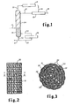
- The present invention will be further described, by way of example only, with reference to the accompanying drawings, in which :-
- Fig.l is a schematic representation of a catalytic distillation column for use in this invention.
- Fig.2 is an elevational view of a catalyst belt packing.
- Fig.3 is a cross sectional view of the catalyst belt packing taken along 3-3 of Fig.2.
- Mixed C4 streams containing principally isobutane (I-C4), normal butane (n-C4), butene-1 (B-1), isobutene (I-B), trans butene-2 (TB-2) and cis butene-2 (CB-2) (plus some minor impurities including butadiene), can be treated with cold sulfuric acid to remove isobutene and produce a butylene concentrate. The isobutene removed is recovered from the acid as a polymer (mostly dimer). The isobutene dimer (i.e., some other isobutene polymers as well) and butene concentrate are valuable products.
- A substitute route for accomplishing this same separation has been discovered. It has been found that a distillation column packed with a properly supported acid catalyst can produce a bottom stream containing isobutene polymer (mostly dimer) and. an overhead stream that is relatively free of isobutene. This is surprising since the catalyst used would normally produce mostly heavy isobutene polymers and copolymers if the reaction were conducted in a conventional fixed bed.
- It has been found that a distillation column packed with a properly supported acid catalyst into which the mixed C4 stream and methanol are fed can produce a bottom stream containing methyl tertiary butyl ether and an overhead stream that is relatively free of isobutene.
- The success of the catalytic distillation approach lies in an understanding of the principles associated with distillation. First, because the reaction is occurring concurrently with distillation, the initial reaction product, e.g., methyl tertiary butyl ether (or diisobutylene) is removed from the reaction zone nearly as quickly as it is formed. This removal of the ether (or isobutene dimer) minimized decomposition of the ether and chaining to form isobutene polymer (or further chaining to large polymer lengths is in the case of dimerization). Second, because all the C4 components are boiling, the temperature of the reaction is controlled by the boiling point of the C4 mixture at the system pressure. The heat of reaction simply creates more boil up, but no increase in temperature. Third, the reaction has an increased driving force because the reaction products have been removed and can not contribute to a reverse reaction (LeChatelier's Principle).
- As a result, a great deal of control over the rate of reaction and distribution of products can be achieved by regulating the system pressure. Also, adjusting the through-put (residence time = liquid hourly space velocity-1) gives further control of product distribution and degree of isobutene removal.
- The temperature in the reactor is determined by the boiling point of the C4's at any given pressure, that is, at constant pressure a change in the temperature of the system, indicates a change in the composition in the column. Thus, to change the temperature the pressure is changed. By increasing the pressure, the temperature in the system is increased. Generally, pressures in the range of 0 to 400 psig are or may be employed, preferably 30 to 150 psig. For the C4 stream, the present reaction will be carried out generally at pressures in the range of 10 to 300 psig, which will generally mean temperatures in the range of 10 to 100°C.
- The reaction of isobutene with itself is equilibrium limited; however, by carrying out the reaction in a distillation column reactor and fractionating the formed product (diisobutene) downward away from the reaction zone, the equilibrium is constantly disrupted and hence the reaction never comes to equilibrium. This has the advantage of course, of achieving an effective 100% conversion (provided the catalyst bed is of sufficient length such that none of the isobutene escapes therefrom to go overhead with the n-butenes). The adjustment of the size of the catalyst bed is a mere mechanical step to be determined for each reactor and in accordance with the reaction conditions.
- The system would normally be considered anhydrous; however, small amounts of water often saturate the feed stream and represent about 400 to 600 ppm thereof. The process will continue to operate in the same fashion, in the presence of this amount of water; however, the following effects have been observed:
- (1) all of the rates increase, however, the lower rates increase faster. (Although not mentioned above, those in the art will recognize that there is a reaction of isobutene with butene to produce "codimer". This rate is normally much slower than the diisobutene rate).
- (2) the amount of codimer increases and (3) tertiary butanol is produced in small amounts.
- The feed to the distillation column reactor is made at the lower end of the catalyst bed, preferably into the catalyst to allow immediate contact of the isobutene with the catalyst.
- The reaction of isobutene with methanol is equilibtium limited; however, by carrying out the reaction in a distillation column reactor and fractionating the formed product, methyl tertiary butyl ether (MTBB), downward away from the reaction zone, the equilibrium is constantly disrupted and hence the reaction never comes to equilibrium. This has the advantage of course, of achieving an effective 100% conversion, provided the catalyst bed is of sufficient length such that none of the isobutene escapes therefrom to go overhead with the n-butenes (a problem the Hauschild process does not solve). The adjustment of the size of the catalyst bed is a mere mechanical step to be determined for each reactor and in accordance with the reaction conditions.
- The MTBE system would normally be considered anyydrous; however, small amounts of water often saturate the feed stream and represent about 400 to 600 ppm thereof. The process will continue to operate in the same fashion, in the presence of this amount of water. Generally the system will be employed with less than 1 mole t water in the feed. However, the limitation on water is relevant to the MTBE reaction. Quite obviously, where water is a reactant or a principal component of a feed stream according to the generic invention, it may be present in substantially larger amounts as required,
- The feed of the distillation column reactor is made at the lower end of the catalyst bed for the MTBE reaction, preferably into the catalyst to allow immediate contact of the isobutene and methanol with the catalyst which is characterized as the feed zone.
- A reflux is preferably included in the system. The reflux ratio could vary over the rate of 1 to 20:1. In practice, the higher ratio may be used to compensate for a short catalyst bed such as required for experimental work. In commercial size units the catalyst bed would be provided so that lower reflux and hence higher unit productivity could be obtained.
- The cation resins are those which have been used in the prior art for this reaction. Catalysts suitable for the new MTBE process are cation exchanger, which contain sulfonic acid groups, and which have been obtained by polymerization or copolymerization of aromatic vinyl compounds followed by sulfonation. Examples of aromatic vinyl compounds suitable for preparing polymers or copolymers are: styrene, vinyl toluene, vinyl naphthalene, vinyl ethylbenzene, methyl styrene, vinyl chlorobenzene and vinyl xylene. A large variety of methods may be used for preparing these polymers; for example, polymerization alone or in admixture with other monovinyl compounds, or by crosslinking with polyvinyl compounds; for example, with divinyl benzene, divinyl toluene, divinylphenylether and others. The polymers may be prepared in the presence or absence of solvents or dispersing agents, and various polymerization initiators may be used, e.g., inorganic or organic peroxides, persulfates, etc.
- The sulfonic acid group may be introduced into these vinyl aromatic polymers by various known methods; for example, by sulfating the polymers with concentrated sulfuric acid or chlorosulfonic acid, or by copolymerizing aromatic compounds which contain sulfonic acid groups (see e.g., U.S. Pat. No. 2,366,007). Further, sulfonic acid groups may be introduced into these polymers which already contain sulfonic acid groups; for example, by treatment with fuming sulfuric acid, - i.e.,sulfuric acid which contains sulfur trioxide. The treatment with fuming fulfuric acid is preferably carried out at 0 to 150°C, and the sulfuric acid should contain sufficient sulfur trioxide after the reaction. The resulting products preferably contain an average of 1.3 to 1.8 sulfonic acid groups per aromatic nucleus. Particularly, suitable polymers which contain sulfonic acid groups are copolymers of aromatic monovinyl compounds with aromatic polyvinyl compounds, particularly, divinyl compounds, in which the polyvinyl benzene content is preferably 1 to 20% by weight of the copolymer (see, for example, German Patent Specification 908,247).
- The ion exchange resin is preferably used in a granular size of about 0.25 to 1 mm, although particles from 0.15 mm up to about 1 mm may be employed. The finer catalysts provide high surface area, but also result in high pressure drops through the reactor. The macroreticular form of these catalysts is preferred because of the much larger surface area exposed and the limited swelling which all of these resins undergo in a non-aqueous hydrocarbon medium.
- Similarly, other acid resins are suitable, such as perflurosulfonic acid resins which are copolymers of sulfonyl fluorovinyl ethyl and fluorocarbon and described in greater detail in DuPont "Innovation", Volume 4, No. 3, Spring 1973 or the modified forms thereof as described in U.S. Pat. No.'s 3,784,399; 3,770,567 and 3,849,243.
- Fig. 1 illustrates schematically a typical distillation column in which the present process may be carried out. The column 10 was a one inch diameter, five foot tall tube containing two feet of conventional glass 1/16
inch helices 18 and three feet of the catalytic packing as shown in Figs. 2 and 3. - Fig. 2 shows a
cloth belt 30 wrapped in open mesh knittedstainless steel wire 31. Thecloth bag 30 is composed of a plurality ofvertical pockets 32 sewn into the bag. Eachpocket 32 is filled withresin catalyst 33. - The wire mesh provides the support for the catalyst (belt) and provides some degree of vapor passage through the catalyst beads, which otherwise form a very compact bed which has a high pressure drop. Thus, the down flowing liquid is in intimate contact with the rising vapors in the column.
- In commercial-scale operations, it is contemplated, catalyst packing would be made up of alternating layers of resin-filled cloth belts similar to the ones described above, and a spacing material which could be of any convenient, suitable substance, such as a corrugated wire screen or wire cloth or a knitted wire mesh. The layers would be arranged vertically to provide vapor passages between the belts. The cylindrical resin-filled pockets could be oriented either vertically or horizontally. For simplicity of fabrication and for better distribution of vapor flow passages, a vertical orientation is preferred. The height of a section of this packing could be of any convenient dimension, from a few inches to several feet. For each of assembly and installation, the packing would be made into sections of the desired shape and size, each section fastened together with circumferential bands or tie wires depending on its size and shape. A complete assembly in a column would consist of several sections, arranged in layers, with the orientation of the resin-filled belts turned at right angles in successive layers to improve liquid and vapor flow distribution.
- Other configurations which may be useful but with certain draw backs would be cages of wire cloth to contain catalyst beads, immersed in liquid on a conventional sieve tray. Disadvantages would be the restriction of vapor flow by the close weave of the wire, which may be compensated by allowing the beads to move freely in the cage, thereby causing attrition. Similarly, suspension of the catalyst on a tray would present problems of attrition, maintaining suspension and preventing catalyst from leaving the tray.
- In the laboratory column the bags are made in the form of a cloth belt approximately six inches wide with narrow pockets approximately 3/4 inch wide sewn across the belt. The pockets are spaced about 1/8 inch apart. These pockets are filled with the catalyst beads to form approximately cylindrical containers, and the open ends are then sewn closed to confine the beads. This belt is then twisted into a helical form to fit inside the one inch column. Twisted in with the belt is also a strip of an open mesh knitted stainless steel wire, which serves to separate the resin filled cloth pockets and provide a passage for vapor flow.
- In operation, during the dimerization, the isobutene containing C4 feed enters through line 11 into the lower end of the
catalytic zone 24 which contains the catalyst bag belt 25 as described. The temperature and pressure in the column are such that the C4 boils up in the column, however, as the isobutene contacts the catalyst, dimer is formed, which being higher boiling than the C4 stream, passes to the bottom of the reactor where it is removed vialine 20 with a portion being recovered throughline 21 and another portion recycled into reboiler 19 throughline 22 and hence back into the bottom of the column 10 throughline 23. - Meanwhile, the n-butenes pass upward through the
catalyst zone 24 and out of the column 10 vialine 12 to condenser 13 hence intoaccumulator 15 vialine 14. A portion is recovered as butene concentrate fromline 16 and a portion is returned as reflux through line 17 into column 10. - In the following examples*, the feed rate of C4's to the column is adjusted to maintain a bottoms temperature which would correspond to low C4 concentration. The catalyst employed was
Amberlyst 15, manufactured by Rohm and Haas, Philadelphia Pa. The C4 feed had the following composition:
* Examples 1, 2, 3, 9 and 10 - The laboratory distillation-reactor column was a one inch diameter, five foot tall tube containing two feet of conventional glass 1/16 inch helices and three feet of the catalytic packing. The pilot column is 3 inches in diameter with 10 feet of catalyst packing and 5 feet of conventional 3/8 inch pall rings.
- In operation, the isobutene containing C4 feed and methanol enters' into the lower end of the catalytic zone which contains the catalyst bag belt as described. The temperature and pressure in the column are such that the C4 and methanol boil up in the column, however, as the isobutene and alcohol contact the catalyst, ether is formed, which being higher boiling than the C4 stream, passes to the bottom of the reactor where it is removed. Generally a portion is recovered through and another portion recycled into a reboiler and hence back into the bottom of the column.
- Meanwhile, the n-butenes pass upward through the catalyst zone and out of the column to a condenser hence into an accumulator. In normal operation, a portion is recovered as butene concentrate and a portion is returned as reflux through into the column.
- These runs illustrate MTBE production.

- These examples illustrate the production of high purity isobutene from methyl tertiary butyl ether. The one inch laboratory column was used and packed with 72 grams of catalyst distillation packing as described in pockets of a cloth belt. The catalyst was in the lower portion of the column for this reaction and the feed (MTBE) was at the upper end of the catalyst bed. Two runs were made using two different purities of feed. The conditions and results are set out below:

- Example 6 illustrates the flexibility of the present process to produce high purity diisobutene from the reaction of methanol and isobutene or MTBE only. The three inch pilot column was used. In Example 7 the column was modified by adding an additional 5 feet of column. In Example 6, the column contained 5 feet of conventional Pall ring in the lower portion and 10 feet of the catalyst in cloth bags in the upper portion. In Example 7, an additional 2.5 feet of catalyst packing was added and 2.5 feet of 1/4 inch conventional saddles on top of that. In both runs, methanol was fed at the top of the catalyst bed and the C4 feed (as described above) was fed below the catalyst bed. The feed rates were adjusted to obtain the desired product distribution.
- In Example 8, high purity methyl tertiary butyl ether (99%) was the feed to column as employed in Example 7. The MTBE was fed into the column at the bottom of the catalyst bed. There was essentially no over head removed except that necessary for analysis. The example demonstrates a unique method for producing diisobutene having a very low codimer contamination. The condition and results of the runs are described below:

- System Pressure = 70psig
- Catalytic zone temperature = 60°C
-

- System Pressure = 40 psig
- Catalytic zone temperature = 40°C
-

Claims (14)
Applications Claiming Priority (6)
| Application Number | Priority Date | Filing Date | Title |
|---|---|---|---|
| US05/928,397 US4242530A (en) | 1978-07-27 | 1978-07-27 | Process for separating isobutene from C4 streams |
| US928397 | 1978-07-27 | ||
| US13559 | 1979-02-21 | ||
| US13730 | 1979-02-21 | ||
| US06/013,730 US4215011A (en) | 1979-02-21 | 1979-02-21 | Catalyst system for separating isobutene from C4 streams |
| US06/013,559 US4232177A (en) | 1979-02-21 | 1979-02-21 | Catalytic distillation process |
Publications (3)
| Publication Number | Publication Date |
|---|---|
| EP0008860A1 true EP0008860A1 (en) | 1980-03-19 |
| EP0008860B1 EP0008860B1 (en) | 1985-10-16 |
| EP0008860B2 EP0008860B2 (en) | 1991-12-04 |
Family
ID=27359889
Family Applications (1)
| Application Number | Title | Priority Date | Filing Date |
|---|---|---|---|
| EP79301451A Expired - Lifetime EP0008860B2 (en) | 1978-07-27 | 1979-07-20 | Catalyst system |
Country Status (4)
| Country | Link |
|---|---|
| EP (1) | EP0008860B2 (en) |
| BE (1) | BE882387A (en) |
| CA (1) | CA1125728A (en) |
| DE (1) | DE2967531D1 (en) |
Cited By (9)
| Publication number | Priority date | Publication date | Assignee | Title |
|---|---|---|---|---|
| AT384015B (en) * | 1981-04-10 | 1987-09-25 | Snam Progetti | METHOD FOR PRODUCING A TERT.ALKYLETHER |
| EP0745576A1 (en) * | 1995-06-01 | 1996-12-04 | SNAMPROGETTI S.p.A. | Process for the joint production of ethers and hydrocarbons with a high octane number |
| FR2739096A1 (en) * | 1995-09-25 | 1997-03-28 | Erdoelchemie Gmbh | PROCESS AND DEVICE FOR CONVERTING OLEFINS TO C3-C12 BY ACID CATALYSIS |
| EP0885866A1 (en) * | 1997-06-20 | 1998-12-23 | Catalytic Distillation Technologies | Etherification process |
| EP0428265B2 (en) † | 1989-11-13 | 2000-05-17 | Koch-Glitsch, Inc | Process and structure for effecting catalytic reactions in distillation structure |
| WO2012084950A1 (en) | 2010-12-21 | 2012-06-28 | Total Raffinage Marketing | Production of fuel additives via simultaneous dehydration and skeletal isomerisation of isobutanol on acid catalysts followed by etherification |
| CN104324683A (en) * | 2014-10-27 | 2015-02-04 | 汤恩旗 | Machinable catalytic screen mesh belt |
| CN105561911A (en) * | 2015-12-16 | 2016-05-11 | 福州大学 | Catalyst bundled packet filler in efficient catalytic distillation column and preparation method thereof |
| US9587138B2 (en) | 2011-10-07 | 2017-03-07 | Nuplex Resins B.V. | Crosslinkable composition |
Families Citing this family (29)
| Publication number | Priority date | Publication date | Assignee | Title |
|---|---|---|---|---|
| US4356339A (en) * | 1980-12-15 | 1982-10-26 | Nippon Oil Company, Limited | Process for isolating and recovering butene-1 of high purity |
| IT1137527B (en) * | 1981-04-10 | 1986-09-10 | Anic Spa | PROCEDURE FOR THE PREPARATION OF TERTIARY ALCHYL ETHERS |
| NZ200039A (en) * | 1981-04-10 | 1984-07-06 | Snam Progetti | Decomposition of alkyl t-alkyl ethers to produce olefins and alcohols |
| EP0216944A1 (en) * | 1985-09-02 | 1987-04-08 | Uop Inc. | Mixed-phase hydrocarbon conversion process employing overhead condenser |
| US4624748A (en) * | 1984-06-29 | 1986-11-25 | Chevron Research Company | Catalyst system for use in a distillation column reactor |
| US4925989A (en) * | 1987-06-01 | 1990-05-15 | Texaco Inc. | MTBE preparation from isobutylene/TBA and methanol in presence of an acid resin catalyst |
| DE3868763D1 (en) * | 1987-08-04 | 1992-04-09 | Erdoelchemie Gmbh | METHOD FOR CLEAVING ALKYL-TERT.-ALKYL ETHERS. |
| FR2628418B1 (en) * | 1988-03-08 | 1991-01-04 | Inst Francais Du Petrole | PROCESS FOR THE PREPARATION OF A TERTIARY ALKYL ETHER BY REACTIVE DISTILLATION |
| FR2628737B1 (en) * | 1988-03-21 | 1990-08-24 | Inst Francais Du Petrole | PROCESS FOR THE PREPARATION OF A TERTIARY ALKYL ETHER BY REACTIVE DISTILLATION |
| US4847223A (en) * | 1988-04-08 | 1989-07-11 | Concordia University | Superacidic catalysts for low temperature conversion of aqueous ethanol to ethylene |
| WO1990002603A1 (en) * | 1988-09-02 | 1990-03-22 | Gebrüder Sulzer Aktiengesellschaft | Device for carrying out catalytic reactions |
| US4982022A (en) * | 1989-08-28 | 1991-01-01 | Chemical Research & Licensing Company | Process for the preparation of tertiary alcohols |
| EP0466954A1 (en) * | 1990-07-17 | 1992-01-22 | CHEMICAL RESEARCH & LICENSING COMPANY | Catalytic distillation |
| US5118873A (en) * | 1990-11-19 | 1992-06-02 | Chemical Research & Licensing Company | Process for the preparation of mtbe |
| FR2678846B1 (en) * | 1991-07-09 | 1994-04-29 | Inst Francais Du Petrole | DISTILLATION-REACTION DEVICE AND ITS USE IN PARTICULAR FOR THE SYNTHESIS OF ETHER. |
| DE69223288T2 (en) * | 1991-07-09 | 1998-03-19 | Inst Francais Du Petrole | Distillation reactor and its use for equilibrium reactions |
| FR2686803A1 (en) * | 1992-02-04 | 1993-08-06 | Inst Francais Du Petrole | Reaction-distillation device and its use for carrying out balanced reactions |
| AU654757B2 (en) * | 1992-02-10 | 1994-11-17 | Chemical Research & Licensing Company | Selective hydrogenation of C5 streams |
| US5348710A (en) * | 1993-06-11 | 1994-09-20 | Johnson Kenneth H | Catalytic distillation structure |
| DE4322712A1 (en) * | 1993-07-08 | 1995-01-12 | Huels Chemische Werke Ag | Process for carrying out chemical reactions in reaction distillation columns |
| FR2743079B1 (en) | 1995-12-27 | 1998-02-06 | Inst Francais Du Petrole | PROCESS AND DEVICE FOR SELECTIVE HYDROGENATION BY CATALYTIC DISTILLATION INCLUDING A LIQUID-GAS UPWARD CO-CURRENT REACTION ZONE |
| FR2743080B1 (en) | 1995-12-27 | 1998-02-06 | Inst Francais Du Petrole | PROCESS FOR SELECTIVE REDUCTION OF THE CONTENT OF BENZENE AND LIGHT UNSATURATED COMPOUNDS OF A HYDROCARBON CUP |
| FR2743081B1 (en) | 1995-12-27 | 1998-01-30 | Inst Francais Du Petrole | PROCESS FOR SELECTIVE REDUCTION OF THE CONTENT OF BENZENE AND LIGHT UNSATURATED COMPOUNDS OF A HYDROCARBON CUP |
| FR2744458B1 (en) | 1996-02-05 | 1998-03-27 | Inst Francais Du Petrole | PROCESS FOR ISOMERIZING PARAFFINS BY REACTIVE DISTILLATION |
| US5925685A (en) * | 1996-11-18 | 1999-07-20 | Catalytic Distillation Technologies | Method for carrying out heterogeneous catalysis |
| US6565816B1 (en) | 1997-06-25 | 2003-05-20 | Koch-Glitsch, Inc. | Saddle structure for reactive distillation |
| DE19728732A1 (en) | 1997-07-04 | 1999-01-07 | Basf Ag | Process for the recovery of isobutene from such containing C¶4¶ hydrocarbon mixtures |
| PT1184361E (en) | 2000-08-29 | 2004-09-30 | Bp Koln Gmbh | PROCESS FOR THE SELECTIVE PREPARATION OF DIISOBUTILENE FROM A C4 CURRENT CONTAINING I-BUTYEN |
| JP6150102B2 (en) * | 2013-02-15 | 2017-06-21 | 有限会社桐山製作所 | Distillation packing |
Citations (8)
| Publication number | Priority date | Publication date | Assignee | Title |
|---|---|---|---|---|
| US2403672A (en) * | 1943-11-13 | 1946-07-09 | Phillips Petroleum Co | Separation of olefins |
| US2552692A (en) * | 1947-11-20 | 1951-05-15 | Phillips Petroleum Co | Extraction of isobutylene by polymerization and depolymerization |
| DE1194398B (en) * | 1960-07-14 | 1965-06-10 | Bayer Ag | Process for the preparation of oligomers of isobutene |
| FR2012552A1 (en) * | 1968-07-09 | 1970-03-20 | Shell Int Research | Tertiary olefins prodn and purification - using an ion-exchange catalyst |
| FR2141474A1 (en) * | 1971-06-03 | 1973-01-26 | Pioneer Research Inc | Propellant - using hydrazine fuel in contact with raney cobalt solid catalyst |
| US4039590A (en) * | 1974-05-21 | 1977-08-02 | Snam Progetti S.P.A. | Process for the synthesis of methyl-tert-butyl ether from methanol and isobutylene in the presence of butadiene |
| FR2356620A1 (en) * | 1976-07-02 | 1978-01-27 | Huels Chemische Werke Ag | PROCESS FOR PREPARING PURE METHYL-TERTIO-BUTYL ETHER |
| US4100220A (en) * | 1977-06-27 | 1978-07-11 | Petro-Tex Chemical Corporation | Dimerization of isobutene |
-
1979
- 1979-07-20 DE DE7979301451T patent/DE2967531D1/en not_active Expired
- 1979-07-20 EP EP79301451A patent/EP0008860B2/en not_active Expired - Lifetime
- 1979-07-25 CA CA332,503A patent/CA1125728A/en not_active Expired
-
1980
- 1980-03-21 BE BE6/47113A patent/BE882387A/en not_active IP Right Cessation
Patent Citations (8)
| Publication number | Priority date | Publication date | Assignee | Title |
|---|---|---|---|---|
| US2403672A (en) * | 1943-11-13 | 1946-07-09 | Phillips Petroleum Co | Separation of olefins |
| US2552692A (en) * | 1947-11-20 | 1951-05-15 | Phillips Petroleum Co | Extraction of isobutylene by polymerization and depolymerization |
| DE1194398B (en) * | 1960-07-14 | 1965-06-10 | Bayer Ag | Process for the preparation of oligomers of isobutene |
| FR2012552A1 (en) * | 1968-07-09 | 1970-03-20 | Shell Int Research | Tertiary olefins prodn and purification - using an ion-exchange catalyst |
| FR2141474A1 (en) * | 1971-06-03 | 1973-01-26 | Pioneer Research Inc | Propellant - using hydrazine fuel in contact with raney cobalt solid catalyst |
| US4039590A (en) * | 1974-05-21 | 1977-08-02 | Snam Progetti S.P.A. | Process for the synthesis of methyl-tert-butyl ether from methanol and isobutylene in the presence of butadiene |
| FR2356620A1 (en) * | 1976-07-02 | 1978-01-27 | Huels Chemische Werke Ag | PROCESS FOR PREPARING PURE METHYL-TERTIO-BUTYL ETHER |
| US4100220A (en) * | 1977-06-27 | 1978-07-11 | Petro-Tex Chemical Corporation | Dimerization of isobutene |
Cited By (10)
| Publication number | Priority date | Publication date | Assignee | Title |
|---|---|---|---|---|
| AT384015B (en) * | 1981-04-10 | 1987-09-25 | Snam Progetti | METHOD FOR PRODUCING A TERT.ALKYLETHER |
| EP0428265B2 (en) † | 1989-11-13 | 2000-05-17 | Koch-Glitsch, Inc | Process and structure for effecting catalytic reactions in distillation structure |
| EP0745576A1 (en) * | 1995-06-01 | 1996-12-04 | SNAMPROGETTI S.p.A. | Process for the joint production of ethers and hydrocarbons with a high octane number |
| FR2739096A1 (en) * | 1995-09-25 | 1997-03-28 | Erdoelchemie Gmbh | PROCESS AND DEVICE FOR CONVERTING OLEFINS TO C3-C12 BY ACID CATALYSIS |
| DE19535505B4 (en) * | 1995-09-25 | 2010-04-22 | Innovene Manufacturing Deutschland Gmbh | Process for the acid-catalyzed conversion of C3-C12 olefins and device suitable for this purpose |
| EP0885866A1 (en) * | 1997-06-20 | 1998-12-23 | Catalytic Distillation Technologies | Etherification process |
| WO2012084950A1 (en) | 2010-12-21 | 2012-06-28 | Total Raffinage Marketing | Production of fuel additives via simultaneous dehydration and skeletal isomerisation of isobutanol on acid catalysts followed by etherification |
| US9587138B2 (en) | 2011-10-07 | 2017-03-07 | Nuplex Resins B.V. | Crosslinkable composition |
| CN104324683A (en) * | 2014-10-27 | 2015-02-04 | 汤恩旗 | Machinable catalytic screen mesh belt |
| CN105561911A (en) * | 2015-12-16 | 2016-05-11 | 福州大学 | Catalyst bundled packet filler in efficient catalytic distillation column and preparation method thereof |
Also Published As
| Publication number | Publication date |
|---|---|
| EP0008860B1 (en) | 1985-10-16 |
| EP0008860B2 (en) | 1991-12-04 |
| DE2967531D1 (en) | 1985-11-21 |
| BE882387A (en) | 1980-07-16 |
| CA1125728A (en) | 1982-06-15 |
Similar Documents
| Publication | Publication Date | Title |
|---|---|---|
| EP0008860B1 (en) | Catalyst system | |
| US4307254A (en) | Catalytic distillation process | |
| US4232177A (en) | Catalytic distillation process | |
| US4215011A (en) | Catalyst system for separating isobutene from C4 streams | |
| US4336407A (en) | Catalytic distillation process | |
| US4302356A (en) | Process for separating isobutene from C4 streams | |
| US4242530A (en) | Process for separating isobutene from C4 streams | |
| US4504687A (en) | Method for etherifications | |
| US5248836A (en) | Process for the preparation of ETBE | |
| EP0415310B1 (en) | Process for the production of tertiary alcohols | |
| US4482775A (en) | Isomerization of C4 alkenes | |
| US4536373A (en) | Contact structure for use in catalytic distillation | |
| EP0466954A1 (en) | Catalytic distillation | |
| EP0487264B1 (en) | Process for the preparation of MTBE | |
| JP2807314B2 (en) | Method for producing methyl t-butyl ether | |
| US5231234A (en) | Two stage production of ether from tertiary alcohol | |
| US6936742B2 (en) | Production of diisobutene from tertiary butyl alcohol | |
| EP0390596B1 (en) | Combined etherification and alkylation process | |
| US4510336A (en) | Transetherification method | |
| US5204064A (en) | Apparatus for conducting a catalytic distillation process | |
| EP0485078B1 (en) | Process for the production of MTBE | |
| EP0189683B1 (en) | Alkylation of organic aromatic compounds | |
| JPS6363254B2 (en) | ||
| JPH0124540B2 (en) | ||
| Smith Jr et al. | Process for separating isobutene from C 4 streams |
Legal Events
| Date | Code | Title | Description |
|---|---|---|---|
| PUAI | Public reference made under article 153(3) epc to a published international application that has entered the european phase |
Free format text: ORIGINAL CODE: 0009012 |
|
| AK | Designated contracting states |
Designated state(s): DE FR GB IT NL |
|
| ITCL | It: translation for ep claims filed |
Representative=s name: TOP PATENT |
|
| DET | De: translation of patent claims | ||
| 17P | Request for examination filed | ||
| ITF | It: translation for a ep patent filed |
Owner name: TOP - PATENTS - ITALO INCOLLINGO |
|
| GRAA | (expected) grant |
Free format text: ORIGINAL CODE: 0009210 |
|
| AK | Designated contracting states |
Designated state(s): DE FR GB IT NL |
|
| REF | Corresponds to: |
Ref document number: 2967531 Country of ref document: DE Date of ref document: 19851121 |
|
| ET | Fr: translation filed | ||
| PLBI | Opposition filed |
Free format text: ORIGINAL CODE: 0009260 |
|
| 26 | Opposition filed |
Opponent name: BASF AKTIENGESELLSCHAFT, LUDWIGSHAFEN Effective date: 19860705 |
|
| NLR1 | Nl: opposition has been filed with the epo |
Opponent name: BASF AKTIENGESELLSCHAFT |
|
| RAP2 | Party data changed (patent owner data changed or rights of a patent transferred) |
Owner name: CHEMICAL RESEARCH & LICENSING COMPANY |
|
| ITTA | It: last paid annual fee | ||
| PUAH | Patent maintained in amended form |
Free format text: ORIGINAL CODE: 0009272 |
|
| STAA | Information on the status of an ep patent application or granted ep patent |
Free format text: STATUS: PATENT MAINTAINED AS AMENDED |
|
| 27A | Patent maintained in amended form |
Effective date: 19911204 |
|
| AK | Designated contracting states |
Kind code of ref document: B2 Designated state(s): DE FR GB IT NL |
|
| NLR2 | Nl: decision of opposition | ||
| ET3 | Fr: translation filed ** decision concerning opposition | ||
| ITF | It: translation for a ep patent filed |
Owner name: JACOBACCI & PERANI S.P.A. |
|
| NLR3 | Nl: receipt of modified translations in the netherlands language after an opposition procedure | ||
| PGFP | Annual fee paid to national office [announced via postgrant information from national office to epo] |
Ref country code: FR Payment date: 19970620 Year of fee payment: 19 |
|
| PGFP | Annual fee paid to national office [announced via postgrant information from national office to epo] |
Ref country code: DE Payment date: 19970624 Year of fee payment: 19 |
|
| PGFP | Annual fee paid to national office [announced via postgrant information from national office to epo] |
Ref country code: NL Payment date: 19970625 Year of fee payment: 19 |
|
| PGFP | Annual fee paid to national office [announced via postgrant information from national office to epo] |
Ref country code: GB Payment date: 19970626 Year of fee payment: 19 |
|
| PG25 | Lapsed in a contracting state [announced via postgrant information from national office to epo] |
Ref country code: GB Free format text: LAPSE BECAUSE OF NON-PAYMENT OF DUE FEES Effective date: 19980720 |
|
| PG25 | Lapsed in a contracting state [announced via postgrant information from national office to epo] |
Ref country code: NL Free format text: LAPSE BECAUSE OF NON-PAYMENT OF DUE FEES Effective date: 19990201 |
|
| GBPC | Gb: european patent ceased through non-payment of renewal fee |
Effective date: 19980720 |
|
| PG25 | Lapsed in a contracting state [announced via postgrant information from national office to epo] |
Ref country code: FR Free format text: LAPSE BECAUSE OF NON-PAYMENT OF DUE FEES Effective date: 19990331 |
|
| NLV4 | Nl: lapsed or anulled due to non-payment of the annual fee |
Effective date: 19990201 |
|
| PG25 | Lapsed in a contracting state [announced via postgrant information from national office to epo] |
Ref country code: DE Free format text: LAPSE BECAUSE OF NON-PAYMENT OF DUE FEES Effective date: 19990501 |
|
| REG | Reference to a national code |
Ref country code: FR Ref legal event code: ST |