EP0007855B1 - Appareil d'usinage à rayonnement laser - Google Patents
Appareil d'usinage à rayonnement laser Download PDFInfo
- Publication number
- EP0007855B1 EP0007855B1 EP79400499A EP79400499A EP0007855B1 EP 0007855 B1 EP0007855 B1 EP 0007855B1 EP 79400499 A EP79400499 A EP 79400499A EP 79400499 A EP79400499 A EP 79400499A EP 0007855 B1 EP0007855 B1 EP 0007855B1
- Authority
- EP
- European Patent Office
- Prior art keywords
- axis
- article
- optical system
- shut
- occultation
- Prior art date
- Legal status (The legal status is an assumption and is not a legal conclusion. Google has not performed a legal analysis and makes no representation as to the accuracy of the status listed.)
- Expired
Links
- 230000005855 radiation Effects 0.000 title description 11
- 230000003287 optical effect Effects 0.000 claims abstract description 35
- 239000011261 inert gas Substances 0.000 claims abstract description 11
- 238000003466 welding Methods 0.000 claims abstract description 10
- 239000002184 metal Substances 0.000 claims abstract description 8
- 238000003754 machining Methods 0.000 claims abstract description 7
- 230000015572 biosynthetic process Effects 0.000 claims abstract description 4
- 230000001427 coherent effect Effects 0.000 claims abstract description 4
- 230000004907 flux Effects 0.000 claims abstract 2
- 239000007787 solid Substances 0.000 claims abstract 2
- XKRFYHLGVUSROY-UHFFFAOYSA-N Argon Chemical compound [Ar] XKRFYHLGVUSROY-UHFFFAOYSA-N 0.000 claims description 4
- 239000007789 gas Substances 0.000 claims description 3
- 229910052786 argon Inorganic materials 0.000 claims description 2
- 230000002093 peripheral effect Effects 0.000 claims description 2
- XLYOFNOQVPJJNP-UHFFFAOYSA-N water Substances O XLYOFNOQVPJJNP-UHFFFAOYSA-N 0.000 claims description 2
- 238000001816 cooling Methods 0.000 claims 1
- 239000003517 fume Substances 0.000 description 5
- 239000012768 molten material Substances 0.000 description 4
- 230000003647 oxidation Effects 0.000 description 4
- 238000007254 oxidation reaction Methods 0.000 description 4
- 239000000126 substance Substances 0.000 description 4
- 230000004888 barrier function Effects 0.000 description 3
- 230000006870 function Effects 0.000 description 3
- 239000004744 fabric Substances 0.000 description 2
- 230000004927 fusion Effects 0.000 description 2
- 230000002745 absorbent Effects 0.000 description 1
- 239000002250 absorbent Substances 0.000 description 1
- 239000006229 carbon black Substances 0.000 description 1
- 150000001875 compounds Chemical class 0.000 description 1
- 239000012809 cooling fluid Substances 0.000 description 1
- 238000007599 discharging Methods 0.000 description 1
- 230000009977 dual effect Effects 0.000 description 1
- 230000005670 electromagnetic radiation Effects 0.000 description 1
- 229910052732 germanium Inorganic materials 0.000 description 1
- GNPVGFCGXDBREM-UHFFFAOYSA-N germanium atom Chemical compound [Ge] GNPVGFCGXDBREM-UHFFFAOYSA-N 0.000 description 1
- 238000009434 installation Methods 0.000 description 1
- 229910001338 liquidmetal Inorganic materials 0.000 description 1
- 239000000155 melt Substances 0.000 description 1
- 238000000034 method Methods 0.000 description 1
- 210000000056 organ Anatomy 0.000 description 1
- 239000002245 particle Substances 0.000 description 1
- 230000001681 protective effect Effects 0.000 description 1
- 230000009993 protective function Effects 0.000 description 1
- 230000000630 rising effect Effects 0.000 description 1
- 238000007789 sealing Methods 0.000 description 1
- 238000011144 upstream manufacturing Methods 0.000 description 1
- 238000001429 visible spectrum Methods 0.000 description 1
Images

Classifications
-
- B—PERFORMING OPERATIONS; TRANSPORTING
- B23—MACHINE TOOLS; METAL-WORKING NOT OTHERWISE PROVIDED FOR
- B23K—SOLDERING OR UNSOLDERING; WELDING; CLADDING OR PLATING BY SOLDERING OR WELDING; CUTTING BY APPLYING HEAT LOCALLY, e.g. FLAME CUTTING; WORKING BY LASER BEAM
- B23K26/00—Working by laser beam, e.g. welding, cutting or boring
- B23K26/16—Removal of by-products, e.g. particles or vapours produced during treatment of a workpiece
Definitions
- the present invention essentially relates to a machining apparatus, in particular welding, by laser radiation, of the type in which a beam of coherent light of axis XX ′ is concentrated, by means of an optical focusing system, on practically area punctual of a workpiece, for example a metal workpiece, so as to cause, in the vicinity of said area, the formation of a fusion bath, a flow of inert gas being projected onto said workpiece near said fusion bath .
- Machining operations in particular welding, subject the optical focusing system, which is one of the most fragile and directly exposed elements of laser beam devices, to particularly severe operating conditions: fumes, projections of liquid metal droplets from the molten pool, etc.
- the flow of inert gas has a dual function: to protect the optical system against fumes and splashes and to protect the weld pool from oxidation.
- this first protective function is very insufficient, due to the fact that the gas flow is only very imperfectly opposed to the rising of particles of molten material.
- the optical system is rapidly deteriorated, its average duration of use not exceeding about 300 hours.
- the laser beam is interrupted, even for short periods, by shutting off the beam upstream of the lens.
- the optical system absorbs a non-negligible part of the energy of this beam, this results in an increase in its temperature and a mechanical deformation which varies its optical characteristics. Frequent interruptions and restorations of the beam cause a thermal imbalance of the optical system, which means that it is necessary to wait a certain time after each restoration of the current before the optical system has regained its thermal equilibrium.
- the object of the invention is to provide more effective protection of the focusing optics than currently known devices, in particular against splashes of molten material, so as to increase its duration of use.
- the invention also aims to allow the interruption of the laser beam while ensuring the thermal balance of the optical focusing system.
- Another object of the invention is to provide effective protection of the workpiece against oxidation.
- the invention provides an apparatus provided with a protection assembly which comprises a concealment device disposed between the optical system and the workpiece and comprising at least one blade or the like secured to a hub rotatably mounted about an axis YY 'parallel to the axis XX' and offset laterally with respect to the latter, so as to partially and periodically intercept the light beam and to deflect from their trajectory the droplets of molten material projected from said bath towards said optical system.
- a protection assembly which comprises a concealment device disposed between the optical system and the workpiece and comprising at least one blade or the like secured to a hub rotatably mounted about an axis YY 'parallel to the axis XX' and offset laterally with respect to the latter, so as to partially and periodically intercept the light beam and to deflect from their trajectory the droplets of molten material projected from said bath towards said optical system.
- Such a rotary occultation device constitutes a real barrier which prevents the droplets from reaching the optical system while allowing the passage of radiation.
- the protection assembly also comprises a shutter device designed to completely intercept the light beam outside the periods of use of the device.
- Such a shutter device makes it possible to interrupt the light beam without interrupting the supply of the radiation source, therefore without causing a thermal imbalance of the optical system.
- the aforementioned concealment and shutter devices are mounted on a sliding support arranged below the aforementioned optical system and actuated by a jack, said support being designed to occupy two positions for which either devices is on the path of the laser beam from said optical system.
- This mounting method allows easy installation of either device depending on the use of the device.
- the above-mentioned rotary occultation device is housed in a chamber provided in the aforementioned sliding support and traversed by an inert gas.
- This embodiment makes it possible to protect the optical system against fumes during the machining operations while also ensuring the protection of the workpiece against oxidation.
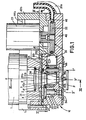
- the welding device essentially comprises a casing of generally cylindrical shape 1, inside which are housed a source (not shown) known per se, emitting coherent electromagnetic radiation located or not in the visible spectrum, and a focusing optical system 2 of axis XX 'and constituted for example by a monocrystalline germanium lens.
- the optical system 2 receives the radiation emitted by the source and transforms it into a conical beam with apex S.
- This conical beam passes through an orifice 3 in the wall 4 which closes the lower end of the casing 1 and meets the workpiece P, for example a metal part, which is situated approximately in a plane passing through said vertex S.
- the impact of the radiation thus concentrated by the optical system 2 on a practically punctual area of the part P causes a considerable local rise in its temperature and consequently the formation of a melt in the immediate vicinity of the impact zone.
- the welding device according to the invention is furthermore provided, at its lower part, therefore between the casing 1 and the part P, with a protection assembly generally designated by the reference 10 and intended to protect the optical system against splashes of molten material and against fumes.
- the protection assembly 10 essentially comprises the rotary concealment device 20 and the closure device 30, these two devices being mounted on a common support 40.
- the concealment device 20 comprises a rotary member 21 in the form of a wheel and constituted by a central hub 210, four identical blades 211 a, 211 b, 211 c, 211 d and by a peripheral rim 212.
- the hub 210 is mounted, by means of bearings 213, on a shaft 214 of geometric axis YY 'parallel to the axis XX' of the optical system 2 and offset relative to the latter.
- the four blades 211 a, 211 b, 211 c, 211 d, of substantially rectangular shape are arranged in planes passing through the axis of rotation YY 'and angularly spaced 90 ° relative to each other.
- the wheel 21 is rotated about the axis YY 'by a friction roller 22 engaged with the rim 212 and itself driven by an electric motor 23.
- the dimensions of the blades as well as the angular speed of rotation of the wheel 21 are determined experimentally as a function of the linear speed of the projections which go up towards the optical system.
- the wheel 21 and the roller 22 are housed in a chamber 41 of the support 40, this chamber being provided with two coaxial orifices 42a and 42b for the passage of the conical beam coming from the optical focusing system, l space between these two orifices being swept by the blades of the wheel 21.
- the sealing arrangement 30 consists of a striated layer 31 made of a substance capable of absorbing the radiation emitted by the source, for example a compound based on carbon black. This substance is placed on a circular plate 32 provided with a threaded rod 33 and fixed by means of a nut 34 to the support 40.
- the device 30 is surrounded by an annular chamber 35 communicating with pipes 36a and 36b connected to pipes 37a, 37b, for supplying and discharging a cooling fluid, for example water, the function of which is to absorb the calories resulting from the laser radiation.
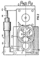
- the support 40 is mounted on the bottom wall 4 of the casing 1 by means of two crossed roller slides 43a and 43b, and is driven in translation by a jack 44 whose body 44a is mounted on a base 1 fixed to the casing 1 and the rod 44b of which is integral with an arm 40b of the support 40.
- the jack 44 is designed to move the support from an extreme position and for which the vertical median of each blade coincides, during its passage between the two orifices 42a and 42b, with the axis XX ', the other for which the axis ZZ' of the shutter system coincides with the axis XX '.
- a seal 45 on the support 40 surrounds the orifice 42a as well as the plate 32 carrying the absorbent substance 31.
- the support 40 is provided with an orifice 46 which communicates with the chamber 41 and to which is connected a tube 49 which delivers an inert gas from a source (not shown), for example argon.
- a source for example argon.
- This gas is introduced into the chamber 41 at a rate which can be five liters per minute for example, and it can only be evacuated from the said chamber through the lower orifice 42b, creating a current from top to bottom.
- the support 40 is provided on its underside with a notch 47 into which the orifice 42b opens.
- This notch 47 is closed by a metallic fabric 48 fixed on the lower wall of the support 40 and provided with an orifice 48a concentric with the orifices 42a and 42b and provided by the passage of the laser beam.
- the droplets of molten metal which are projected upwards and have passed through the wire mesh 48 are deflected by the blades of the wheel 21, while the fumes are prevented from entering, due to the flow of inert gas, into the chamber 41. Furthermore, the inert gas maintained in the notch 47 creates and diffuses through the wire mesh, above the workpiece, a "drag" of protection.
- the support 40 occupies the other position, that is to say that for which the axis ZZ 'coincides with the axis XX'.
- the radiation emitted by the source, which continues to be supplied, is absorbed by substance 31.
- the optical system 2 is in temperature equilibrium and the device is ready for a new welding operation, without changing the setting.
- the source supply is of course cut off for a permanent shutdown of the device.
Landscapes
- Engineering & Computer Science (AREA)
- Physics & Mathematics (AREA)
- Optics & Photonics (AREA)
- Plasma & Fusion (AREA)
- Mechanical Engineering (AREA)
- Laser Beam Processing (AREA)
- Lasers (AREA)
Applications Claiming Priority (2)
| Application Number | Priority Date | Filing Date | Title |
|---|---|---|---|
| FR7822349A FR2431899A1 (fr) | 1978-07-28 | 1978-07-28 | Appareil d'usinage a rayonnement laser |
| FR7822349 | 1978-07-28 |
Publications (2)
| Publication Number | Publication Date |
|---|---|
| EP0007855A1 EP0007855A1 (fr) | 1980-02-06 |
| EP0007855B1 true EP0007855B1 (fr) | 1981-06-24 |
Family
ID=9211300
Family Applications (1)
| Application Number | Title | Priority Date | Filing Date |
|---|---|---|---|
| EP79400499A Expired EP0007855B1 (fr) | 1978-07-28 | 1979-07-13 | Appareil d'usinage à rayonnement laser |
Country Status (4)
| Country | Link |
|---|---|
| EP (1) | EP0007855B1 (enExample) |
| AT (1) | ATE93T1 (enExample) |
| DE (1) | DE2960429D1 (enExample) |
| FR (1) | FR2431899A1 (enExample) |
Families Citing this family (1)
| Publication number | Priority date | Publication date | Assignee | Title |
|---|---|---|---|---|
| GB8600214D0 (en) * | 1986-01-07 | 1986-02-12 | Quantum Laser Uk Ltd | Gas shroud |
Family Cites Families (1)
| Publication number | Priority date | Publication date | Assignee | Title |
|---|---|---|---|---|
| DD123788A1 (enExample) * | 1976-01-09 | 1977-01-19 |
-
1978
- 1978-07-28 FR FR7822349A patent/FR2431899A1/fr active Granted
-
1979
- 1979-07-13 EP EP79400499A patent/EP0007855B1/fr not_active Expired
- 1979-07-13 AT AT79400499T patent/ATE93T1/de active
- 1979-07-13 DE DE7979400499T patent/DE2960429D1/de not_active Expired
Also Published As
| Publication number | Publication date |
|---|---|
| FR2431899A1 (fr) | 1980-02-22 |
| FR2431899B1 (enExample) | 1980-12-12 |
| EP0007855A1 (fr) | 1980-02-06 |
| ATE93T1 (de) | 1981-07-15 |
| DE2960429D1 (en) | 1981-10-01 |
Similar Documents
| Publication | Publication Date | Title |
|---|---|---|
| EP0481869B1 (fr) | Buse de traitement de surface par laser, avec apport de poudre | |
| CA2946958C (fr) | Module de turbomachine comportant un carter autour d'un equipement avec un capot de recuperation d'huile de lubrification | |
| FR2658378A1 (fr) | Chalumeau a plasma rotatif. | |
| FR2552838A1 (fr) | Mecanisme planetaire a billes reglable de facon continue | |
| FR2476289A1 (fr) | Dispositif de chargement pour fours a cuve | |
| FR2626498A1 (fr) | Dispositif d'irrigation par pulverisation a installer en terre | |
| EP0007855B1 (fr) | Appareil d'usinage à rayonnement laser | |
| EP0006805B1 (fr) | Appareil de distribution de particules solides | |
| FR2613637A1 (fr) | Engrenage pour broyeur a auge | |
| EP0474557A1 (fr) | Laser utilisé pour des usinages de pièces mécaniques | |
| EP0785025A1 (fr) | Machine à granuler | |
| EP0730666A1 (fr) | Dispositif de chargement d'un four a cuve | |
| FR2648737A1 (fr) | Dispositif pour un laser de puissance | |
| EP3804898B1 (fr) | Torche de soudage électrique sous gaz avec aspiration de fumées, et équipement de soudage associé comprenant une telle torche | |
| CA1129250A (fr) | Pompe helico-centrifuge de circulation de fluide | |
| EP0692684B1 (fr) | Dispositif de génération d'un courant d'air chaud | |
| EP0545780B1 (fr) | Appareil de mesure de l'activité alpha d'une solution | |
| EP0515249A1 (fr) | Dispositif d'étanchéité partielle entre l'intérieur et l'extérieur d'un four à arc | |
| EP0001028A1 (fr) | Rebrûleuse rotative pour articles en verre | |
| EP1567281A1 (fr) | Procede et installation de pointage d'un jet fin de fluide, notamment en soudage, usinage, ou rechargement laser | |
| EP0151435B1 (fr) | Four à micro-ondes équipé d'un brasseur d'ondes | |
| BE674774A (enExample) | ||
| FR2611109A1 (fr) | Installations de soudure automatique a l'etain | |
| EP0816002A1 (fr) | Boíte de confinement de gaz utilisée avec une tête de soudage | |
| WO2025012177A1 (fr) | Dispositif d'observation pour observer un procédé générant des vapeurs métalliques |
Legal Events
| Date | Code | Title | Description |
|---|---|---|---|
| PUAI | Public reference made under article 153(3) epc to a published international application that has entered the european phase |
Free format text: ORIGINAL CODE: 0009012 |
|
| 17P | Request for examination filed | ||
| AK | Designated contracting states |
Designated state(s): AT BE CH DE FR GB IT LU NL SE |
|
| GRAA | (expected) grant |
Free format text: ORIGINAL CODE: 0009210 |
|
| AK | Designated contracting states |
Designated state(s): BE CH DE FR GB LU |
|
| REF | Corresponds to: |
Ref document number: 93 Country of ref document: AT Date of ref document: 19810715 Kind code of ref document: T |
|
| REF | Corresponds to: |
Ref document number: 2960429 Country of ref document: DE Date of ref document: 19811001 |
|
| EPTA | Lu: last paid annual fee | ||
| PGFP | Annual fee paid to national office [announced via postgrant information from national office to epo] |
Ref country code: FR Payment date: 19970613 Year of fee payment: 19 |
|
| PGFP | Annual fee paid to national office [announced via postgrant information from national office to epo] |
Ref country code: BE Payment date: 19970617 Year of fee payment: 19 |
|
| PGFP | Annual fee paid to national office [announced via postgrant information from national office to epo] |
Ref country code: GB Payment date: 19970620 Year of fee payment: 19 |
|
| PGFP | Annual fee paid to national office [announced via postgrant information from national office to epo] |
Ref country code: DE Payment date: 19970623 Year of fee payment: 19 |
|
| PGFP | Annual fee paid to national office [announced via postgrant information from national office to epo] |
Ref country code: CH Payment date: 19970630 Year of fee payment: 19 |
|
| PGFP | Annual fee paid to national office [announced via postgrant information from national office to epo] |
Ref country code: LU Payment date: 19970908 Year of fee payment: 19 |
|
| PG25 | Lapsed in a contracting state [announced via postgrant information from national office to epo] |
Ref country code: LU Free format text: LAPSE BECAUSE OF NON-PAYMENT OF DUE FEES Effective date: 19980713 Ref country code: GB Free format text: LAPSE BECAUSE OF NON-PAYMENT OF DUE FEES Effective date: 19980713 |
|
| PG25 | Lapsed in a contracting state [announced via postgrant information from national office to epo] |
Ref country code: CH Free format text: LAPSE BECAUSE OF NON-PAYMENT OF DUE FEES Effective date: 19980731 Ref country code: BE Free format text: LAPSE BECAUSE OF NON-PAYMENT OF DUE FEES Effective date: 19980731 |
|
| BERE | Be: lapsed |
Owner name: LA SOUDURE AUTOGENE FRANCAISE Effective date: 19980731 |
|
| GBPC | Gb: european patent ceased through non-payment of renewal fee |
Effective date: 19980713 |
|
| REG | Reference to a national code |
Ref country code: CH Ref legal event code: PL |
|
| PG25 | Lapsed in a contracting state [announced via postgrant information from national office to epo] |
Ref country code: FR Free format text: LAPSE BECAUSE OF NON-PAYMENT OF DUE FEES Effective date: 19990331 |
|
| PG25 | Lapsed in a contracting state [announced via postgrant information from national office to epo] |
Ref country code: DE Free format text: LAPSE BECAUSE OF NON-PAYMENT OF DUE FEES Effective date: 19990501 |
|
| REG | Reference to a national code |
Ref country code: FR Ref legal event code: ST |
|
| PLBE | No opposition filed within time limit |
Free format text: ORIGINAL CODE: 0009261 |
|
| STAA | Information on the status of an ep patent application or granted ep patent |
Free format text: STATUS: NO OPPOSITION FILED WITHIN TIME LIMIT |