EP0007722B1 - Extrusion apparatus - Google Patents
Extrusion apparatus Download PDFInfo
- Publication number
- EP0007722B1 EP0007722B1 EP79301301A EP79301301A EP0007722B1 EP 0007722 B1 EP0007722 B1 EP 0007722B1 EP 79301301 A EP79301301 A EP 79301301A EP 79301301 A EP79301301 A EP 79301301A EP 0007722 B1 EP0007722 B1 EP 0007722B1
- Authority
- EP
- European Patent Office
- Prior art keywords
- leg
- sections
- line
- pool
- pipe
- Prior art date
- Legal status (The legal status is an assumption and is not a legal conclusion. Google has not performed a legal analysis and makes no representation as to the accuracy of the status listed.)
- Expired
Links
Images
Classifications
-
- B—PERFORMING OPERATIONS; TRANSPORTING
- B29—WORKING OF PLASTICS; WORKING OF SUBSTANCES IN A PLASTIC STATE IN GENERAL
- B29C—SHAPING OR JOINING OF PLASTICS; SHAPING OF MATERIAL IN A PLASTIC STATE, NOT OTHERWISE PROVIDED FOR; AFTER-TREATMENT OF THE SHAPED PRODUCTS, e.g. REPAIRING
- B29C44/00—Shaping by internal pressure generated in the material, e.g. swelling or foaming ; Producing porous or cellular expanded plastics articles
- B29C44/34—Auxiliary operations
- B29C44/3403—Foaming under special conditions, e.g. in sub-atmospheric pressure, in or on a liquid
- B29C44/3407—Vacuum extrusion using underwater barometric leg
-
- B—PERFORMING OPERATIONS; TRANSPORTING
- B29—WORKING OF PLASTICS; WORKING OF SUBSTANCES IN A PLASTIC STATE IN GENERAL
- B29C—SHAPING OR JOINING OF PLASTICS; SHAPING OF MATERIAL IN A PLASTIC STATE, NOT OTHERWISE PROVIDED FOR; AFTER-TREATMENT OF THE SHAPED PRODUCTS, e.g. REPAIRING
- B29C44/00—Shaping by internal pressure generated in the material, e.g. swelling or foaming ; Producing porous or cellular expanded plastics articles
- B29C44/34—Auxiliary operations
- B29C44/36—Feeding the material to be shaped
- B29C44/46—Feeding the material to be shaped into an open space or onto moving surfaces, i.e. to make articles of indefinite length
- B29C44/50—Feeding the material to be shaped into an open space or onto moving surfaces, i.e. to make articles of indefinite length using pressure difference, e.g. by extrusion or by spraying
- B29C44/505—Feeding the material to be shaped into an open space or onto moving surfaces, i.e. to make articles of indefinite length using pressure difference, e.g. by extrusion or by spraying extruding the compound through a flat die
-
- Y—GENERAL TAGGING OF NEW TECHNOLOGICAL DEVELOPMENTS; GENERAL TAGGING OF CROSS-SECTIONAL TECHNOLOGIES SPANNING OVER SEVERAL SECTIONS OF THE IPC; TECHNICAL SUBJECTS COVERED BY FORMER USPC CROSS-REFERENCE ART COLLECTIONS [XRACs] AND DIGESTS
- Y10—TECHNICAL SUBJECTS COVERED BY FORMER USPC
- Y10S—TECHNICAL SUBJECTS COVERED BY FORMER USPC CROSS-REFERENCE ART COLLECTIONS [XRACs] AND DIGESTS
- Y10S264/00—Plastic and nonmetallic article shaping or treating: processes
- Y10S264/78—Processes of molding using vacuum
-
- Y—GENERAL TAGGING OF NEW TECHNOLOGICAL DEVELOPMENTS; GENERAL TAGGING OF CROSS-SECTIONAL TECHNOLOGIES SPANNING OVER SEVERAL SECTIONS OF THE IPC; TECHNICAL SUBJECTS COVERED BY FORMER USPC CROSS-REFERENCE ART COLLECTIONS [XRACs] AND DIGESTS
- Y10—TECHNICAL SUBJECTS COVERED BY FORMER USPC
- Y10S—TECHNICAL SUBJECTS COVERED BY FORMER USPC CROSS-REFERENCE ART COLLECTIONS [XRACs] AND DIGESTS
- Y10S425/00—Plastic article or earthenware shaping or treating: apparatus
- Y10S425/06—Vacuum
Definitions
- This invention relates generally as indicated to a foam extrusion apparatus and more particularly to the construction and fabrication of a large barometric leg which when evacuated is essentially filled with water but which includes a vacuum chamber at its upper end into which the extrudate passes from the die for expansion.
- a foam board or billet extrusion line including a foam extrusion apparatus which includes an inclined elongated pipe forming a barometric leg extending from a first higher elevation to a pool of water at a second lower elevation, characterised in that the pipe (32) is supported by an inclined ramp (22) and in that the pipe includes a linear series of concrete sections inter-connected and sealed to form a vacuum chamber.
- the invention also provides a foam board or billet extrusion line including a foam extrusion apparatus which includes an inclined elongated pipe of circular cross-section forming a barometric leg extending from a first higher elevation to a pool of water at a second lower elevation, characterised in that the pipe (32) is supported by an inclined ramp (22) and in that the pipe includes a linear series of concrete sections interconnected and sealed to form a vacuum chamber and further characterised in that the lower end of said leg extends only partially into such pool of water, and in that a baffle (118) is located over the upper part of the lowermost section projecting into the pool (29).
- a foam extrusion apparatus which includes an inclined elongated pipe of circular cross-section forming a barometric leg extending from a first higher elevation to a pool of water at a second lower elevation, characterised in that the pipe (32) is supported by an inclined ramp (22) and in that the pipe includes a linear series of concrete sections interconnected and sealed to form a vacuum chamber and further characterised in that the lower
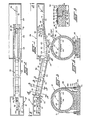
- An inclined ramp 22 extends from the front edge 23 of the second platform to a position 24 which is beneath the facing edge of the first platform 20.
- the platforms 20 and 21 may constitute the floors of two separate buildings, respectively shown at 26 and 27 which are horizontally spaced and at different elevations.
- the platform 20 is provided with a pool 29 which may be formed of reinforced sprayed concrete much in the fashion of an ordinary Gunite swimming pool.
- An elongated pipe or barometric leg shown generally at 32 is positioned on the ramp 22 and extends from the edge 23 of the upper platform or building through end wall 34 confining the pool 29.
- the barometric leg or pipeline 32 may be covered as well as walkways 35 providing access on either side to the leg and interconnecting the upper and lower buildings.
- the horizontal and vertical spacing of the buildings are greatly foreshortened for convenience of illustration only.
- the platform 21 may be approximately 8.6 meters above the platform 20 and the leg 32 may be approximately 52.8 meters long and inclined at an angle of approximately 12°. It will be appreciated that the length and angle of inclination may vary.
- the leg or pipeline Because of the length and size of the leg or pipeline, it is fabricated in sections joined end-to- end and sealed. Each of the sections is supported on the ramp 22 to form a continuous linear pipeline of the length indicated.
- the leg or pipeline may be formed of twenty-two sections, each 2.4 meters in length. Each section may be approximately 1.68 meters in inside diameter having a wall thickness of approximately 15.87 cm.
- the sections illustrated are fabricated of reinforced concrete similar in form to large diameter sewer or water pipe sections. Such sections are generally similar in form and will not each be described in detail.
- a mixing extruder 37 and a somewhat larger cooling extruder 38 in tandem forcing the extrudate through pipe 39 to a die, not shown, on the inside of the bulkhead 40 closing the upper end of the leg in the position illustrated.
- the extruders may each be mounted for movement toward and away from the upper end of the leg as is the bulkhead to provide access to the die interiorly of the leg and to open and close the upper end of the leg.
- a conveyor 42 which includes a belt 43 trained above and below conveyor rolls 44 journaled within the sections of the leg. As seen in Figs. 3 and 4, above the rolls 44 the conveyor belt is moving up the leg and below the belt it is moving down the leg supporting the foam extrudate as indicated at 46 maintaining the extrudate spaced from the walls of the leg. Without the conveyor, the extrudate would simply float to the top of the pipeline or leg.
- rollers 47 As the belt enters the pool 29, it passes beneath a large number of rollers 47 arranged in a long radius extending upwardly, of, for example, 30.5 meters. There may be a large number of such rollers and they may be spaced approximately 13 per meter.
- the belt 43 extends beneath such rollers and about relatively large diameter drive sheave 50 driven by motor 51.
- the belt then passes between idler sheaves 52 and 53 and about tensioning sheave 54 which may be urged upwardly by weight 55 connected to such sheave by cable trained around pulley 56.
- the extrudate As the extrudate passes beneath the drive sheave 50, it will leave the pool of water and from the conveyor 43 to a cut-off 58 the extrudate will be supported on a series of rolls 59 which may be arranged again in a long radius of the approximate extent of 30.5 meters but this time the center of the radius is beneath the extrudate.
- the roller arrangement 47 and 59 is in the arrangement of a reverse curve with the rollers 47 supporting the belt 43 while the rollers 59 underlie the extrudate and form an idler roller table therefor moving the same into the cut-off.
- the ramp 22 extending between the upper and lower platforms may include special footers such as seen at 62 and 63 in Fig. 1 to resist gravitational forces since the ramp extends at approximately an inclination of 12°.
- the leg is formed of substantially similar segments of reinforced concrete pipe which may be supported on or secured to the ramp as indicated more clearly in Figs. 3 and 4.
- the two sections next to the top section may be anchored to the ramp as indicated at 65 and 66. Also, the lowermost section may be anchored to the ramp as seen at 67.
- a typical anchor is seen in greater detail in Fig. 3.
- the pipe section 69 is supported on a port concrete sleeper or grout pad 70 on top of the ramp 22, such sleeper embracing a substantial peripheral portion of the underside of the pipe section.
- a flexible steel band approximately 6.4 mm thick and approximately 45.7 cm wide is wrapped over the top of the pipe section as seen at 71.
- Each end of the strap has secured thereto anchor blocks 72 which include vertical apertures receiving vertically extending bolts 73 which are embedded in the ramp 22 and secured in such ramp by a weld plate 74.
- anchor blocks 72 which include vertical apertures receiving vertically extending bolts 73 which are embedded in the ramp 22 and secured in such ramp by a weld plate 74.
- the upper end of each bolt is threaded to receive a nut 75, which may be tightened to a predetermined torque firmly to clamp the pipe section to the sleeper in turn securing it to the ramp.
- the strap may be positioned essentially centrally of each pipe section.
- pipe sections which are not anchored to the ramp may be simply supported on wooden sleepers, preferably two per section, seen at 77 secured to the ramp by dowel pins 78. Wooden wedges 79 may be employed properly to center the pipe sections.
- the upper pipe section may be provided with a fitting 82 through which line 83 extends connected to vacuum pump 84 whereby the interior of the leg may be evacuated.
- the subatmospheric pressure within the leg may be controlled by a vent valve 85 similarly connected to the interior of the leg through fitting 86.
- each is formed at each end with a bell and spigot to facilitate joining as seen more clearly in Fig. 5.
- the spigot 88 of the section 89 telescopes within the bell 90 of the adjoining section 91.
- An O-ring 92 is provided in a groove in the spigot deformed by the bell in conventional manner.
- the end face of the bell and the adjoining shoulder of the spigot may be calked by oakum which is a loose fiber which is commonly used for the calking of seams of ships as seen at 93.
- An acrylic calking compound seen at 94 may be employed to seal the outer edge of the oakum calking.
- the outer surface of the concrete pipe sections may be provided with two coats of epoxy paint seen at 96 for a width of approximately 30.5 cm centered on the joint.
- Two beads of acrylic calking compound seen at 97 and 98 extend circumferentially of each pipe section.
- a strip of neoprene or buna rubber 99 is then wrapped around the beads of acrylic calking impound.
- One layer is sufficient with an overlap of approximately 30 cm.
- the overlap may be provided with a rubber adhesive on the overlay.
- the neoprene or rubber strip 99 may be approximately 25.4 cm wide by 1.59 mm thick.
- each pipe section may be, if desired, provided with a coating of epoxy paint and if any pinhole leaks develop, grout or putty may be applied exteriorly at the leak to ensure the vacuum integrity of the pipeline as a whole.
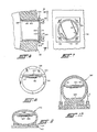
- a plurality of portholes 105 may be cut in the wall of the pipe sections as seen more clearly in Fig. 6.
- the opening may be readily cast in place or provided by a circular concrete saw.
- a fitting 106 which includes a cylindrical element or sleeve 107 which telescopes within the opening 105 from the exterior of the pipe.
- a plate 108 Welded to the exterior of the cylindrical element or sleeve is a plate 108 having a circular opening 109 therein and a square exterior configuration as seen more clearly in Fig.
- a neoprene or like gasket 112 is situated between the plate 108 and the clear plastic plate 111.
- the gasket is of course provided with a circular opening 113 corresponding to the opening 109 in the plate 108.
- the clear plastic plate may be held in place by thumb nuts 114 with washers 115 interposed between the nuts and the clear plate 111.
- the space between the aperture 105 and the exterior of the sleeve 107 may be filled with an epoxy resin or grout indicated at 116 to provide the necessary vacuum seal. Since all of the pressure upon the port fitting will be from the exterior of the pipe, the fitting as shown and constructed has been found quite adequate.
- the lowermost section of the leg which projects through the wall 34 into the pool 29 may be provided with a baffle plate 118.
- the baffle plate is secured by suitable fasteners 120 to the end face 121 of the lowermost pipe section and a suitable gasket or seal may be provided between the baffle plate and such end face.
- the lower edge of the baffle plate is provided with a rectangular cut-out 122.
- the purpose of the baffle is to alter the circular configuration of the lower end of the leg where it enters the pool 29 so that the level of the pool may be drawn down to essentially the top of the cut-out 122 before air bubbles into the leg. This then reduces the weight or head. of water above the extrudate 46 as it traverses through the pool.
- Fig. 9 there is illustrated a concrete pipe section employed to construct the leg.
- the concrete pipe section 162 is similar to the circular sections illustrated and previously described except that it is oval or elliptical in sectional shape.
- Such elliptical pipe sections may be joined in the same manner as seen in Fig. 5 and may be supported on sleepers 163 with wood or concrete wedges 164 being employed to center the sections.
- Conveyor rolls 165 are journaled interiorly of the section with the belt 166 passing above and below the rolls to support the billet or board 167 on the underside thereof.
- Conveyor rolls 165 are journaled interiorly of the section with the belt 166 passing above and below the rolls to support the billet or board 167 on the underside thereof.
- Fig. 10 there is illustrated a slightly modified form of concrete pipe section shown generally at 190.
- the concrete pipe section may be extruded or cast in conventional form but is provided with interior projections 191 and 192 into which may be cast or secured journals for the conveyor rolls 193.
- the bottom interior of the pipe section may be provided with an interior chordal flat or fillet seen at 195 to provide a flat interior bottom to permit maintenance personnel to be conveyed along the interior of the pipeline or leg for the aforementioned maintenance and inspection purposes.
- the concrete pipe sections of Fig. 10 may be anchored to and supported from the ramp in the same manner as in Fig. 3.
Abstract
Description
- This invention relates generally as indicated to a foam extrusion apparatus and more particularly to the construction and fabrication of a large barometric leg which when evacuated is essentially filled with water but which includes a vacuum chamber at its upper end into which the extrudate passes from the die for expansion.
- It is known that the formation of extruded foams in the form of billets or boards is enhanced by the employment of a vacuum chamber so that the expansion of the foam is accomplished under subatmospheric pressure. Examples of vacuum foam extrusion apparatus may be seen in prior U.S. patents to Nelson et al No. 3,584,108, Maxon No. 3,169,272, Cogiano No. 3,822,331 and U.K. patent No. 1,233,088. In vacuum extrusion technology, a most difficult problem to solve is the curing and extraction of the material from the vacuum chamber, especially delicate or fragile material such as styrene foam in the form of large boards or billets. This problem has been solved by the employment of an inclined barometric leg as seen in applicant's prior U.S. patents 3,704,083 and 4,044,084. Other prior suggestions are to be seen in US patents 2,889,581 and 2,987,768.
- On a small or laboratory scale, the construction and operation of a barometric leg is.a relatively simple matter. However, in a large scale plant, a number of problems are encountered in the construction, fabrication and operation of the leg. For example, the size of the leg itself creates a number of problems in view of the forces thereon when the leg is evacuated to form the vacuum chamber and essentially to fill the leg with water.
- In accordance with the present invention there is provided a foam board or billet extrusion line including a foam extrusion apparatus which includes an inclined elongated pipe forming a barometric leg extending from a first higher elevation to a pool of water at a second lower elevation, characterised in that the pipe (32) is supported by an inclined ramp (22) and in that the pipe includes a linear series of concrete sections inter-connected and sealed to form a vacuum chamber.
- The invention also provides a foam board or billet extrusion line including a foam extrusion apparatus which includes an inclined elongated pipe of circular cross-section forming a barometric leg extending from a first higher elevation to a pool of water at a second lower elevation, characterised in that the pipe (32) is supported by an inclined ramp (22) and in that the pipe includes a linear series of concrete sections interconnected and sealed to form a vacuum chamber and further characterised in that the lower end of said leg extends only partially into such pool of water, and in that a baffle (118) is located over the upper part of the lowermost section projecting into the pool (29).
- The following description and the annexed drawings set forth in detail illustrative embodiments of the invention.
- In said annexed drawings:
- Fig. 1 is a side elevation of a two level plant in accordance with the present invention with the two levels being interconnected by the barometric leg, such leg being shown broken away and greatly foreshortened:
- Fig. 2 is a top plan view broken away of the two level plant seen in Fig. 1;
- Fig. 3 is an enlarged transverse section taken substantially on the line 3-3 of Fig. 1 illustrating a preferred circular concrete pipe section and the manner in which one or more of such sections is anchored to the ramp supporting the same;
- Fig. 4 is a view similar to Fig. 3 taken substantially on the line 4-4 of Fig. 1 and illustrating the manner in which the sections may be supported on the ramp;
- Fig. 5 is an enlarged longitudinal fragmentary section through a vacuum seal joint between end- to-end pipe sections as seen from the line 5-5 of Fig. 1;
- Fig. 6 is an enlarged fragmentary section taken substantially from the line 6-6 of Fig. 1 illustrating one of a number of windows or view ports in the barometric leg;
- Fig. 7 is a plan view of the window seen from the line 7-7 of Fig. 6;
- Fig. 8 is a section taken substantially on the line 8-8 of Fig. 1 illustrating the lower end of the barometric leg as it enters the pool illustrating the baffle covering the top portion of the end pipe section;
- Fig. 9 is a transverse section of a concrete pipe section wherein the section is elliptical or oval in cross-section;
- Fig. 10 is a view similar to Fig. 3 but illustrating a slightly modified form of concrete pipe section.
- Referring first to Figs. 1 and 2 it will be seen that there is a
first platform 20 at a lower elevation and asecond platform 21 at a higher elevation horizontally spaced from the first platform. Aninclined ramp 22 extends from thefront edge 23 of the second platform to aposition 24 which is beneath the facing edge of thefirst platform 20. Theplatforms platform 20 is provided with apool 29 which may be formed of reinforced sprayed concrete much in the fashion of an ordinary Gunite swimming pool. - An elongated pipe or barometric leg shown generally at 32 is positioned on the
ramp 22 and extends from theedge 23 of the upper platform or building throughend wall 34 confining thepool 29. As seen more clearly in Fig. 2 the barometric leg orpipeline 32 may be covered as well aswalkways 35 providing access on either side to the leg and interconnecting the upper and lower buildings. In the illustration of Figs. 1 and 2 the horizontal and vertical spacing of the buildings are greatly foreshortened for convenience of illustration only. For example, theplatform 21 may be approximately 8.6 meters above theplatform 20 and theleg 32 may be approximately 52.8 meters long and inclined at an angle of approximately 12°. It will be appreciated that the length and angle of inclination may vary. - Because of the length and size of the leg or pipeline, it is fabricated in sections joined end-to- end and sealed. Each of the sections is supported on the
ramp 22 to form a continuous linear pipeline of the length indicated. For example, the leg or pipeline may be formed of twenty-two sections, each 2.4 meters in length. Each section may be approximately 1.68 meters in inside diameter having a wall thickness of approximately 15.87 cm. As seen from Figs. 3, 4 and 5, the sections illustrated are fabricated of reinforced concrete similar in form to large diameter sewer or water pipe sections. Such sections are generally similar in form and will not each be described in detail. - In the
upper building 27 onplatform 21 there is supported for movement toward and away from the upper end of the leg 32 amixing extruder 37 and a somewhatlarger cooling extruder 38 in tandem forcing the extrudate throughpipe 39 to a die, not shown, on the inside of thebulkhead 40 closing the upper end of the leg in the position illustrated. The extruders may each be mounted for movement toward and away from the upper end of the leg as is the bulkhead to provide access to the die interiorly of the leg and to open and close the upper end of the leg. - Situated within the leg and extending throughout substantially its entire length is a
conveyor 42 which includes abelt 43 trained above and belowconveyor rolls 44 journaled within the sections of the leg. As seen in Figs. 3 and 4, above therolls 44 the conveyor belt is moving up the leg and below the belt it is moving down the leg supporting the foam extrudate as indicated at 46 maintaining the extrudate spaced from the walls of the leg. Without the conveyor, the extrudate would simply float to the top of the pipeline or leg. - As the belt enters the
pool 29, it passes beneath a large number ofrollers 47 arranged in a long radius extending upwardly, of, for example, 30.5 meters. There may be a large number of such rollers and they may be spaced approximately 13 per meter. Thebelt 43 extends beneath such rollers and about relatively largediameter drive sheave 50 driven bymotor 51. The belt then passes between idler sheaves 52 and 53 and about tensioning sheave 54 which may be urged upwardly byweight 55 connected to such sheave by cable trained aroundpulley 56. As the extrudate passes beneath thedrive sheave 50, it will leave the pool of water and from theconveyor 43 to a cut-off 58 the extrudate will be supported on a series ofrolls 59 which may be arranged again in a long radius of the approximate extent of 30.5 meters but this time the center of the radius is beneath the extrudate. - The
roller arrangement rollers 47 supporting thebelt 43 while therollers 59 underlie the extrudate and form an idler roller table therefor moving the same into the cut-off. - It will be appreciated that other processing equipment other than the cut-off may be employed in the
building 26. Additional cutting or forming equipment may be provided and also scrap or reclaim extruders and pelletizers may be included. - The
ramp 22 extending between the upper and lower platforms may include special footers such as seen at 62 and 63 in Fig. 1 to resist gravitational forces since the ramp extends at approximately an inclination of 12°. - When the barometric leg is evacuated, there will also be a substantial axial force thereon occasioned by atmospheric pressure on the
end closure 40. As indicated, the leg is formed of substantially similar segments of reinforced concrete pipe which may be supported on or secured to the ramp as indicated more clearly in Figs. 3 and 4. - In order to resist such axial forces, in the embodiment illustrated in Fig. 1, the two sections next to the top section may be anchored to the ramp as indicated at 65 and 66. Also, the lowermost section may be anchored to the ramp as seen at 67. A typical anchor is seen in greater detail in Fig. 3. The
pipe section 69 is supported on a port concrete sleeper orgrout pad 70 on top of theramp 22, such sleeper embracing a substantial peripheral portion of the underside of the pipe section. A flexible steel band approximately 6.4 mm thick and approximately 45.7 cm wide is wrapped over the top of the pipe section as seen at 71. Each end of the strap has secured theretoanchor blocks 72 which include vertical apertures receiving vertically extendingbolts 73 which are embedded in theramp 22 and secured in such ramp by aweld plate 74. There may be four such bolts on each side of the pipe section. The upper end of each bolt is threaded to receive anut 75, which may be tightened to a predetermined torque firmly to clamp the pipe section to the sleeper in turn securing it to the ramp. The strap may be positioned essentially centrally of each pipe section. - As seen more clearly in Fig. 4, pipe sections which are not anchored to the ramp may be simply supported on wooden sleepers, preferably two per section, seen at 77 secured to the ramp by dowel pins 78.
Wooden wedges 79 may be employed properly to center the pipe sections. - Also as seen in Fig. 4, the upper pipe section may be provided with a fitting 82 through which
line 83 extends connected tovacuum pump 84 whereby the interior of the leg may be evacuated. The subatmospheric pressure within the leg may be controlled by avent valve 85 similarly connected to the interior of the leg through fitting 86. - With the exception of the end faces of the two end sections of the pipe or leg, each is formed at each end with a bell and spigot to facilitate joining as seen more clearly in Fig. 5. The
spigot 88 of thesection 89 telescopes within thebell 90 of the adjoiningsection 91. An O-ring 92 is provided in a groove in the spigot deformed by the bell in conventional manner. However, the end face of the bell and the adjoining shoulder of the spigot may be calked by oakum which is a loose fiber which is commonly used for the calking of seams of ships as seen at 93. An acrylic calking compound seen at 94 may be employed to seal the outer edge of the oakum calking. - The outer surface of the concrete pipe sections may be provided with two coats of epoxy paint seen at 96 for a width of approximately 30.5 cm centered on the joint.
- Two beads of acrylic calking compound seen at 97 and 98 extend circumferentially of each pipe section. A strip of neoprene or
buna rubber 99 is then wrapped around the beads of acrylic calking impound. One layer is sufficient with an overlap of approximately 30 cm. The overlap may be provided with a rubber adhesive on the overlay. The neoprene orrubber strip 99 may be approximately 25.4 cm wide by 1.59 mm thick. - Finally, steel banding straps 101 and 102 are employed and are drawn snug. In the condition illustrated in Fig. 5, the bands are not yet drawn snug and when tightened, they will tend to flatten the beads of calking compound seen at 97 and 98. With the joint illustrated, a suitable vacuum seal is provided.
- The entire exterior of each pipe section may be, if desired, provided with a coating of epoxy paint and if any pinhole leaks develop, grout or putty may be applied exteriorly at the leak to ensure the vacuum integrity of the pipeline as a whole.
- In order to provide visual access to the interior of the pipeline or leg throughout its length and more particularly in the area of the die at the upper end, a plurality of
portholes 105 may be cut in the wall of the pipe sections as seen more clearly in Fig. 6. The opening may be readily cast in place or provided by a circular concrete saw. Situated in the opening is a fitting 106 which includes a cylindrical element orsleeve 107 which telescopes within the opening 105 from the exterior of the pipe. Welded to the exterior of the cylindrical element or sleeve is aplate 108 having acircular opening 109 therein and a square exterior configuration as seen more clearly in Fig. - 7. Secured to the plate at the four corners thereof beyond the circular opening are threaded
studs 110 which pass through holes in clear plastic plate 111. A neoprene or likegasket 112 is situated between theplate 108 and the clear plastic plate 111. The gasket is of course provided with acircular opening 113 corresponding to theopening 109 in theplate 108. The clear plastic plate may be held in place bythumb nuts 114 withwashers 115 interposed between the nuts and the clear plate 111. - Upon assembly, the space between the
aperture 105 and the exterior of thesleeve 107 may be filled with an epoxy resin or grout indicated at 116 to provide the necessary vacuum seal. Since all of the pressure upon the port fitting will be from the exterior of the pipe, the fitting as shown and constructed has been found quite adequate. - With reference now to Fig. 8 it will be seen that the lowermost section of the leg which projects through the
wall 34 into thepool 29 may be provided with abaffle plate 118. The baffle plate is secured bysuitable fasteners 120 to theend face 121 of the lowermost pipe section and a suitable gasket or seal may be provided between the baffle plate and such end face. The lower edge of the baffle plate is provided with a rectangular cut-out 122. The purpose of the baffle is to alter the circular configuration of the lower end of the leg where it enters thepool 29 so that the level of the pool may be drawn down to essentially the top of the cut-out 122 before air bubbles into the leg. This then reduces the weight or head. of water above theextrudate 46 as it traverses through the pool. - Although circular concrete reinforced pipe sections are preferred because of their ready availability, it will be appreciated that the sectional configuration may be other than circular.
- In Fig. 9 there is illustrated a concrete pipe section employed to construct the leg. The
concrete pipe section 162 is similar to the circular sections illustrated and previously described except that it is oval or elliptical in sectional shape. Such elliptical pipe sections may be joined in the same manner as seen in Fig. 5 and may be supported onsleepers 163 with wood or concrete wedges 164 being employed to center the sections. - Conveyor rolls 165 are journaled interiorly of the section with the
belt 166 passing above and below the rolls to support the billet or board 167 on the underside thereof. Again it can be seen that with an elliptical or oval sectional configuration of the pipe a slightly wider conveyor and thus workpiece may be accommodated while still providing interior access below the conveyor. The concrete oval pipe sections may be anchored and supported in the same manner as the circular sections. - In Fig. 10 there is illustrated a slightly modified form of concrete pipe section shown generally at 190. The concrete pipe section may be extruded or cast in conventional form but is provided with
interior projections - Other modes of carrying out the invention may be employed, and changes may be made as regards the particular details described, and illustrated herein, without departing from the invention.
Claims (11)
Priority Applications (1)
| Application Number | Priority Date | Filing Date | Title |
|---|---|---|---|
| AT79301301T ATE11753T1 (en) | 1978-07-10 | 1979-07-05 | DEVICE FOR EXTRUDING. |
Applications Claiming Priority (2)
| Application Number | Priority Date | Filing Date | Title |
|---|---|---|---|
| US05/922,541 US4199310A (en) | 1978-07-10 | 1978-07-10 | Extrusion apparatus |
| US922541 | 1992-07-30 |
Publications (2)
| Publication Number | Publication Date |
|---|---|
| EP0007722A1 EP0007722A1 (en) | 1980-02-06 |
| EP0007722B1 true EP0007722B1 (en) | 1985-02-13 |
Family
ID=25447191
Family Applications (1)
| Application Number | Title | Priority Date | Filing Date |
|---|---|---|---|
| EP79301301A Expired EP0007722B1 (en) | 1978-07-10 | 1979-07-05 | Extrusion apparatus |
Country Status (6)
| Country | Link |
|---|---|
| US (1) | US4199310A (en) |
| EP (1) | EP0007722B1 (en) |
| JP (1) | JPS5514288A (en) |
| AT (1) | ATE11753T1 (en) |
| CA (1) | CA1118173A (en) |
| DE (1) | DE2967383D1 (en) |
Families Citing this family (16)
| Publication number | Priority date | Publication date | Assignee | Title |
|---|---|---|---|---|
| US4271107A (en) * | 1979-11-05 | 1981-06-02 | Condec Corporation | Foam extrusion apparatus and method |
| US4371488A (en) * | 1981-04-02 | 1983-02-01 | U.C. Industries | Method and apparatus for extruding foamed bodies involving the use of adjustable traction shaping rolls |
| US4469652A (en) * | 1982-09-20 | 1984-09-04 | U.C. Industries | Foam extrusion apparatus and method |
| US4454082A (en) * | 1982-09-24 | 1984-06-12 | U.C. Industries | Method and apparatus for monitoring the thickness of a foamed extrudate in an environmental control chamber downstream of an extrusion die |
| JPS5962122A (en) * | 1982-10-02 | 1984-04-09 | Kanegafuchi Chem Ind Co Ltd | Method and apparatus for manufacturing synthetic resin foam |
| AU609736B2 (en) * | 1986-09-19 | 1991-05-09 | Dow Chemical Company, The | Process and apparatus for producing extruded thermoplastic foam bodies |
| EP0386663A1 (en) * | 1989-03-06 | 1990-09-12 | U.C. Industries, Inc. | Method of preparing styrene foams |
| CA2019083C (en) * | 1989-06-20 | 2000-02-01 | Raymond M. Breindel | Process for preparing extruded foam bodies |
| US6093350A (en) * | 1996-08-14 | 2000-07-25 | Owens Corning Fiberglas Technology, Inc. | Sealable chamber extrusion apparatus and method with process controls |
| US5753161A (en) * | 1996-08-14 | 1998-05-19 | Owens-Corning Fiberglas Technology, Inc. | Vacuum extrusion system and method |
| US6036468A (en) | 1997-08-21 | 2000-03-14 | Owens Corning Fiberglas Technology, Inc. | Vacuum extrusion system |
| US5783122A (en) * | 1996-08-14 | 1998-07-21 | Owens Corning Fiberglas Technology, Inc. | Vacuum extrusion apparatus and method |
| US8557884B2 (en) * | 2002-05-31 | 2013-10-15 | Owens Corning Intellectual Capital, Llc | To enhance the thermal insulation of polymeric foam by reducing cell anisotropic ratio and the method for production thereof |
| US7150614B2 (en) * | 2003-12-18 | 2006-12-19 | Owens Corning Fiberglas Technology, Inc. | Horizontal vacuum chamber seal control device |
| US20080314525A1 (en) * | 2007-06-22 | 2008-12-25 | Processing Technologies, Llc. | Web lamination system |
| US11852276B2 (en) * | 2020-04-27 | 2023-12-26 | LISEGA, Inc. | Insulated pipe support |
Family Cites Families (27)
| Publication number | Priority date | Publication date | Assignee | Title |
|---|---|---|---|---|
| BE557063A (en) * | ||||
| US1470529A (en) * | 1921-06-28 | 1923-10-09 | Nat Valvf & Mfg Company | Pipe support and anchor |
| US1646423A (en) * | 1924-03-15 | 1927-10-25 | Schaub Eugene | Cradle for hydraulic pipe lines |
| US1990434A (en) * | 1928-12-12 | 1935-02-05 | Kohler Conrad | Insulating material |
| US2037084A (en) * | 1934-08-01 | 1936-04-14 | American Cast Iron Pipe Co | Leak clamp for pipe joints |
| US2151298A (en) * | 1935-09-07 | 1939-03-21 | Babcock & Wilcox Co | Support for hollow bodies |
| US2113083A (en) * | 1936-02-11 | 1938-04-05 | Thompson Mfg Co | Pipe-line support |
| US2179629A (en) * | 1938-02-15 | 1939-11-14 | United States Pipe Foundry | Reinforced concrete pipe |
| US2307915A (en) * | 1942-03-07 | 1943-01-12 | Chicago Bridge & Iron Co | Support for pipes |
| US2420838A (en) * | 1944-12-07 | 1947-05-20 | Alden E Osborn | Pipe joint |
| DE880677C (en) * | 1947-10-22 | 1953-06-22 | Chem Bautechnische Produkte Ag | Process for sealing cement and spun concrete pipes and sealing material for carrying out the process |
| US2525662A (en) * | 1948-05-07 | 1950-10-10 | Wingfoot Corp | Hose vulcanizing apparatus |
| US2821416A (en) * | 1954-06-10 | 1958-01-28 | Robert M Soehnlen | Housing-forming clamp for bell and spigot pipes of the molded joint type |
| LU35018A1 (en) * | 1955-03-08 | 1900-01-01 | ||
| US2937889A (en) * | 1957-12-10 | 1960-05-24 | Palmese Samuel | Lateral insertion waste pipe connector having an oval hub |
| US3100658A (en) * | 1958-01-27 | 1963-08-13 | Goodrich Co B F | Pipe joint sealing wrapper |
| US2987768A (en) * | 1959-03-25 | 1961-06-13 | Plastex Company | Method and apparatus for extruding plastic conduit |
| CH379853A (en) * | 1959-11-21 | 1964-07-15 | Muecher Hermann | Inner seal for folded cement pipes |
| GB1080305A (en) * | 1965-03-13 | 1967-08-23 | Hepworth Iron Co Ltd | Improvements in or relating to vitrified clay piping or conduit |
| US3459312A (en) * | 1967-04-12 | 1969-08-05 | United States Steel Corp | Car having ladle supporting and positioning means |
| GB1233088A (en) * | 1968-07-19 | 1971-05-26 | ||
| DE1965600A1 (en) * | 1969-12-30 | 1971-07-15 | Karl Dr Glehn | Elimination of the rotation and recess of the ring disc; automatic securing of a level of sole |
| US3704083A (en) * | 1970-06-18 | 1972-11-28 | Arthus L Phipps | Extrusion machine |
| US3799197A (en) * | 1972-04-03 | 1974-03-26 | Fmc Corp | Dual jack assembly for marine loading arms |
| US4107254A (en) * | 1972-09-14 | 1978-08-15 | English Clay Lovering Pochin & Co. Ltd. | Method of lining pipes, molds or other tubular articles with thermosetting plastic material |
| US4044084A (en) * | 1975-08-11 | 1977-08-23 | Phipps Arthur L | Method of removing an article from a chamber having a reduced pressure therein |
| US4101117A (en) * | 1976-07-07 | 1978-07-18 | Stone & Webster Engineering Corporation | Impact energy absorbing pipe restraints |
-
1978
- 1978-07-10 US US05/922,541 patent/US4199310A/en not_active Expired - Lifetime
- 1978-10-12 CA CA000313199A patent/CA1118173A/en not_active Expired
- 1978-12-22 JP JP16096578A patent/JPS5514288A/en active Granted
-
1979
- 1979-07-05 EP EP79301301A patent/EP0007722B1/en not_active Expired
- 1979-07-05 AT AT79301301T patent/ATE11753T1/en not_active IP Right Cessation
- 1979-07-05 DE DE7979301301T patent/DE2967383D1/en not_active Expired
Also Published As
| Publication number | Publication date |
|---|---|
| EP0007722A1 (en) | 1980-02-06 |
| ATE11753T1 (en) | 1985-02-15 |
| JPS6249165B2 (en) | 1987-10-17 |
| JPS5514288A (en) | 1980-01-31 |
| US4199310A (en) | 1980-04-22 |
| DE2967383D1 (en) | 1985-03-28 |
| CA1118173A (en) | 1982-02-16 |
Similar Documents
| Publication | Publication Date | Title |
|---|---|---|
| EP0007722B1 (en) | Extrusion apparatus | |
| CA2134524C (en) | Basement wall construction | |
| US5608998A (en) | Panel for lining manholes and the like | |
| US7240804B2 (en) | Full contact floating roof | |
| US3762110A (en) | Movable windbreaker for steel buildings | |
| KR920009134B1 (en) | Method of repairing fissures in concrete structure | |
| US5590497A (en) | Circular or generally circular prestressed concrete tank and method of constructing same | |
| US5439319A (en) | Tunnel barrier system and method of installing the same | |
| EP0666944A1 (en) | Apparatus for forming a multi-walled containment trench | |
| WO1992014663A2 (en) | Underground structure for hazardous liquid storage tanks | |
| US4934117A (en) | Pitch pocket and method of forming same | |
| US6692183B2 (en) | Hydraulically adjustable manhole ring | |
| US7513712B2 (en) | Device and a method for drainage of water from rock caves | |
| US5133276A (en) | Flotation units | |
| NL8503222A (en) | FOIL ANCHORING WITH AN OUTSIDE ANCHORING SYSTEM. | |
| JPH05503893A (en) | Method for lining the inside of accessible pipes and tunnel rings for carrying out the method | |
| US11000987B2 (en) | Reinforcement of structures using 3D-fabric wrap | |
| US3951173A (en) | Method and apparatus for sealing large diameter pipes | |
| US20050039666A1 (en) | Structural flotation device | |
| JP2003328319A (en) | Repair structure for high structure, and repair method for high structure | |
| Newman | Specification and design of enclosures for gas treatment | |
| KR830001231B1 (en) | Extrusion apparatus and method | |
| GB2179003A (en) | A method of producing a panel | |
| JPH0546427B2 (en) | ||
| CN216892544U (en) | Composite sealing device for underground building deformation joint |
Legal Events
| Date | Code | Title | Description |
|---|---|---|---|
| PUAI | Public reference made under article 153(3) epc to a published international application that has entered the european phase |
Free format text: ORIGINAL CODE: 0009012 |
|
| AK | Designated contracting states |
Designated state(s): AT BE CH DE FR GB IT LU NL SE |
|
| 17P | Request for examination filed | ||
| ITF | It: translation for a ep patent filed |
Owner name: ST. ASSOC. MARIETTI & PIPPARELLI |
|
| GRAA | (expected) grant |
Free format text: ORIGINAL CODE: 0009210 |
|
| AK | Designated contracting states |
Designated state(s): AT BE CH DE FR GB IT LU NL SE |
|
| REF | Corresponds to: |
Ref document number: 11753 Country of ref document: AT Date of ref document: 19850215 Kind code of ref document: T |
|
| REF | Corresponds to: |
Ref document number: 2967383 Country of ref document: DE Date of ref document: 19850328 |
|
| ET | Fr: translation filed | ||
| PLBE | No opposition filed within time limit |
Free format text: ORIGINAL CODE: 0009261 |
|
| STAA | Information on the status of an ep patent application or granted ep patent |
Free format text: STATUS: NO OPPOSITION FILED WITHIN TIME LIMIT |
|
| 26N | No opposition filed | ||
| ITTA | It: last paid annual fee | ||
| EPTA | Lu: last paid annual fee | ||
| EAL | Se: european patent in force in sweden |
Ref document number: 79301301.2 |
|
| PGFP | Annual fee paid to national office [announced via postgrant information from national office to epo] |
Ref country code: FR Payment date: 19980618 Year of fee payment: 20 |
|
| PGFP | Annual fee paid to national office [announced via postgrant information from national office to epo] |
Ref country code: SE Payment date: 19980622 Year of fee payment: 20 |
|
| PGFP | Annual fee paid to national office [announced via postgrant information from national office to epo] |
Ref country code: AT Payment date: 19980623 Year of fee payment: 20 |
|
| PGFP | Annual fee paid to national office [announced via postgrant information from national office to epo] |
Ref country code: DE Payment date: 19980625 Year of fee payment: 20 |
|
| PGFP | Annual fee paid to national office [announced via postgrant information from national office to epo] |
Ref country code: GB Payment date: 19980626 Year of fee payment: 20 |
|
| PGFP | Annual fee paid to national office [announced via postgrant information from national office to epo] |
Ref country code: NL Payment date: 19980629 Year of fee payment: 20 |
|
| PGFP | Annual fee paid to national office [announced via postgrant information from national office to epo] |
Ref country code: CH Payment date: 19980706 Year of fee payment: 20 |
|
| PGFP | Annual fee paid to national office [announced via postgrant information from national office to epo] |
Ref country code: BE Payment date: 19980714 Year of fee payment: 20 |
|
| PGFP | Annual fee paid to national office [announced via postgrant information from national office to epo] |
Ref country code: LU Payment date: 19980727 Year of fee payment: 20 |
|
| BE20 | Be: patent expired |
Free format text: 19990705 *CONDEC CORP. |
|
| PG25 | Lapsed in a contracting state [announced via postgrant information from national office to epo] |
Ref country code: GB Free format text: LAPSE BECAUSE OF NON-PAYMENT OF DUE FEES Effective date: 19990704 Ref country code: CH Free format text: LAPSE BECAUSE OF EXPIRATION OF PROTECTION Effective date: 19990704 |
|
| PG25 | Lapsed in a contracting state [announced via postgrant information from national office to epo] |
Ref country code: NL Free format text: LAPSE BECAUSE OF EXPIRATION OF PROTECTION Effective date: 19990705 Ref country code: LU Free format text: LAPSE BECAUSE OF EXPIRATION OF PROTECTION Effective date: 19990705 Ref country code: AT Free format text: LAPSE BECAUSE OF EXPIRATION OF PROTECTION Effective date: 19990705 |
|
| PG25 | Lapsed in a contracting state [announced via postgrant information from national office to epo] |
Ref country code: SE Free format text: LAPSE BECAUSE OF NON-PAYMENT OF DUE FEES Effective date: 19990706 |
|
| REG | Reference to a national code |
Ref country code: GB Ref legal event code: PE20 Effective date: 19990704 |
|
| REG | Reference to a national code |
Ref country code: CH Ref legal event code: PL |
|
| NLV7 | Nl: ceased due to reaching the maximum lifetime of a patent |
Effective date: 19990705 |