EP0006682A2 - Procédé et appareil pour l'emboutissage au moyen d'un poinçon d'articles creux en matière thermoplastique - Google Patents
Procédé et appareil pour l'emboutissage au moyen d'un poinçon d'articles creux en matière thermoplastique Download PDFInfo
- Publication number
- EP0006682A2 EP0006682A2 EP79300869A EP79300869A EP0006682A2 EP 0006682 A2 EP0006682 A2 EP 0006682A2 EP 79300869 A EP79300869 A EP 79300869A EP 79300869 A EP79300869 A EP 79300869A EP 0006682 A2 EP0006682 A2 EP 0006682A2
- Authority
- EP
- European Patent Office
- Prior art keywords
- sheet
- stretching
- movement
- tool
- tips
- Prior art date
- Legal status (The legal status is an assumption and is not a legal conclusion. Google has not performed a legal analysis and makes no representation as to the accuracy of the status listed.)
- Granted
Links
- 229920001169 thermoplastic Polymers 0.000 title claims abstract description 32
- 239000004416 thermosoftening plastic Substances 0.000 title claims abstract description 32
- 238000000034 method Methods 0.000 title claims abstract description 30
- 239000000463 material Substances 0.000 claims abstract description 61
- 230000010339 dilation Effects 0.000 claims abstract description 20
- 239000012530 fluid Substances 0.000 claims abstract description 16
- 238000000926 separation method Methods 0.000 claims abstract description 16
- 239000013641 positive control Substances 0.000 claims abstract description 8
- 229920003023 plastic Polymers 0.000 claims description 9
- 239000004033 plastic Substances 0.000 claims description 9
- 238000003780 insertion Methods 0.000 claims description 3
- 230000037431 insertion Effects 0.000 claims description 3
- 230000001419 dependent effect Effects 0.000 claims description 2
- 230000000916 dilatatory effect Effects 0.000 claims description 2
- 238000003825 pressing Methods 0.000 claims description 2
- 101100327917 Caenorhabditis elegans chup-1 gene Proteins 0.000 abstract description 5
- -1 polyethylene Polymers 0.000 description 13
- 229920001155 polypropylene Polymers 0.000 description 13
- 239000004743 Polypropylene Substances 0.000 description 11
- VGGSQFUCUMXWEO-UHFFFAOYSA-N Ethene Chemical compound C=C VGGSQFUCUMXWEO-UHFFFAOYSA-N 0.000 description 6
- 239000005977 Ethylene Substances 0.000 description 6
- 229920001577 copolymer Polymers 0.000 description 5
- 229920000098 polyolefin Polymers 0.000 description 5
- KKEYFWRCBNTPAC-UHFFFAOYSA-N Terephthalic acid Chemical compound OC(=O)C1=CC=C(C(O)=O)C=C1 KKEYFWRCBNTPAC-UHFFFAOYSA-N 0.000 description 4
- 239000011521 glass Substances 0.000 description 4
- QQONPFPTGQHPMA-UHFFFAOYSA-N propylene Natural products CC=C QQONPFPTGQHPMA-UHFFFAOYSA-N 0.000 description 4
- 125000004805 propylene group Chemical group [H]C([H])([H])C([H])([*:1])C([H])([H])[*:2] 0.000 description 4
- LYCAIKOWRPUZTN-UHFFFAOYSA-N Ethylene glycol Chemical compound OCCO LYCAIKOWRPUZTN-UHFFFAOYSA-N 0.000 description 3
- 238000001816 cooling Methods 0.000 description 3
- 238000002844 melting Methods 0.000 description 3
- 230000008018 melting Effects 0.000 description 3
- KAKZBPTYRLMSJV-UHFFFAOYSA-N Butadiene Chemical compound C=CC=C KAKZBPTYRLMSJV-UHFFFAOYSA-N 0.000 description 2
- 239000004793 Polystyrene Substances 0.000 description 2
- 229910000831 Steel Inorganic materials 0.000 description 2
- PPBRXRYQALVLMV-UHFFFAOYSA-N Styrene Chemical compound C=CC1=CC=CC=C1 PPBRXRYQALVLMV-UHFFFAOYSA-N 0.000 description 2
- WERYXYBDKMZEQL-UHFFFAOYSA-N butane-1,4-diol Chemical compound OCCCCO WERYXYBDKMZEQL-UHFFFAOYSA-N 0.000 description 2
- 238000006243 chemical reaction Methods 0.000 description 2
- 238000010586 diagram Methods 0.000 description 2
- 150000001993 dienes Chemical class 0.000 description 2
- 230000000694 effects Effects 0.000 description 2
- 229920001971 elastomer Polymers 0.000 description 2
- 235000013312 flour Nutrition 0.000 description 2
- 239000010881 fly ash Substances 0.000 description 2
- QQVIHTHCMHWDBS-UHFFFAOYSA-N isophthalic acid Chemical compound OC(=O)C1=CC=CC(C(O)=O)=C1 QQVIHTHCMHWDBS-UHFFFAOYSA-N 0.000 description 2
- 238000004519 manufacturing process Methods 0.000 description 2
- 239000000155 melt Substances 0.000 description 2
- 229910052751 metal Inorganic materials 0.000 description 2
- 239000002184 metal Substances 0.000 description 2
- 150000002739 metals Chemical class 0.000 description 2
- 239000000203 mixture Substances 0.000 description 2
- 238000000465 moulding Methods 0.000 description 2
- 238000005498 polishing Methods 0.000 description 2
- 229920000573 polyethylene Polymers 0.000 description 2
- 229920005606 polypropylene copolymer Polymers 0.000 description 2
- 229920002223 polystyrene Polymers 0.000 description 2
- 238000007639 printing Methods 0.000 description 2
- 230000003014 reinforcing effect Effects 0.000 description 2
- 239000005060 rubber Substances 0.000 description 2
- 230000035945 sensitivity Effects 0.000 description 2
- 239000010959 steel Substances 0.000 description 2
- 238000007666 vacuum forming Methods 0.000 description 2
- 238000005303 weighing Methods 0.000 description 2
- PRBHEGAFLDMLAL-GQCTYLIASA-N (4e)-hexa-1,4-diene Chemical compound C\C=C\CC=C PRBHEGAFLDMLAL-GQCTYLIASA-N 0.000 description 1
- HECLRDQVFMWTQS-RGOKHQFPSA-N 1755-01-7 Chemical compound C1[C@H]2[C@@H]3CC=C[C@@H]3[C@@H]1C=C2 HECLRDQVFMWTQS-RGOKHQFPSA-N 0.000 description 1
- OEPOKWHJYJXUGD-UHFFFAOYSA-N 2-(3-phenylmethoxyphenyl)-1,3-thiazole-4-carbaldehyde Chemical compound O=CC1=CSC(C=2C=C(OCC=3C=CC=CC=3)C=CC=2)=N1 OEPOKWHJYJXUGD-UHFFFAOYSA-N 0.000 description 1
- WSSSPWUEQFSQQG-UHFFFAOYSA-N 4-methyl-1-pentene Chemical compound CC(C)CC=C WSSSPWUEQFSQQG-UHFFFAOYSA-N 0.000 description 1
- NLHHRLWOUZZQLW-UHFFFAOYSA-N Acrylonitrile Chemical compound C=CC#N NLHHRLWOUZZQLW-UHFFFAOYSA-N 0.000 description 1
- OKTJSMMVPCPJKN-UHFFFAOYSA-N Carbon Chemical compound [C] OKTJSMMVPCPJKN-UHFFFAOYSA-N 0.000 description 1
- XDTMQSROBMDMFD-UHFFFAOYSA-N Cyclohexane Chemical compound C1CCCCC1 XDTMQSROBMDMFD-UHFFFAOYSA-N 0.000 description 1
- IMROMDMJAWUWLK-UHFFFAOYSA-N Ethenol Chemical compound OC=C IMROMDMJAWUWLK-UHFFFAOYSA-N 0.000 description 1
- 235000019738 Limestone Nutrition 0.000 description 1
- 241000237503 Pectinidae Species 0.000 description 1
- 239000004698 Polyethylene Substances 0.000 description 1
- CDBYLPFSWZWCQE-UHFFFAOYSA-L Sodium Carbonate Chemical compound [Na+].[Na+].[O-]C([O-])=O CDBYLPFSWZWCQE-UHFFFAOYSA-L 0.000 description 1
- XTXRWKRVRITETP-UHFFFAOYSA-N Vinyl acetate Chemical compound CC(=O)OC=C XTXRWKRVRITETP-UHFFFAOYSA-N 0.000 description 1
- NIXOWILDQLNWCW-UHFFFAOYSA-N acrylic acid group Chemical group C(C=C)(=O)O NIXOWILDQLNWCW-UHFFFAOYSA-N 0.000 description 1
- 239000000654 additive Substances 0.000 description 1
- 125000001931 aliphatic group Chemical group 0.000 description 1
- 238000013459 approach Methods 0.000 description 1
- TZCXTZWJZNENPQ-UHFFFAOYSA-L barium sulfate Chemical compound [Ba+2].[O-]S([O-])(=O)=O TZCXTZWJZNENPQ-UHFFFAOYSA-L 0.000 description 1
- 230000005540 biological transmission Effects 0.000 description 1
- 230000015572 biosynthetic process Effects 0.000 description 1
- 238000007664 blowing Methods 0.000 description 1
- 239000005388 borosilicate glass Substances 0.000 description 1
- 125000000484 butyl group Chemical group [H]C([*])([H])C([H])([H])C([H])([H])C([H])([H])[H] 0.000 description 1
- 239000004927 clay Substances 0.000 description 1
- 230000006835 compression Effects 0.000 description 1
- 238000007906 compression Methods 0.000 description 1
- 229920001887 crystalline plastic Polymers 0.000 description 1
- 239000010459 dolomite Substances 0.000 description 1
- 229910000514 dolomite Inorganic materials 0.000 description 1
- 230000008030 elimination Effects 0.000 description 1
- 238000003379 elimination reaction Methods 0.000 description 1
- 238000004049 embossing Methods 0.000 description 1
- 125000001495 ethyl group Chemical group [H]C([H])([H])C([H])([H])* 0.000 description 1
- 238000001125 extrusion Methods 0.000 description 1
- 239000010439 graphite Substances 0.000 description 1
- 229910002804 graphite Inorganic materials 0.000 description 1
- 238000009499 grossing Methods 0.000 description 1
- 229920001903 high density polyethylene Polymers 0.000 description 1
- 229920005669 high impact polystyrene Polymers 0.000 description 1
- 229920001519 homopolymer Polymers 0.000 description 1
- 229910052500 inorganic mineral Inorganic materials 0.000 description 1
- 239000006028 limestone Substances 0.000 description 1
- 229920001684 low density polyethylene Polymers 0.000 description 1
- 229920001179 medium density polyethylene Polymers 0.000 description 1
- 125000005395 methacrylic acid group Chemical class 0.000 description 1
- 125000002496 methyl group Chemical group [H]C([H])([H])* 0.000 description 1
- 125000001570 methylene group Chemical group [H]C([H])([*:1])[*:2] 0.000 description 1
- 239000010445 mica Substances 0.000 description 1
- 229910052618 mica group Inorganic materials 0.000 description 1
- 239000011707 mineral Substances 0.000 description 1
- 238000012986 modification Methods 0.000 description 1
- 230000004048 modification Effects 0.000 description 1
- 150000002848 norbornenes Chemical class 0.000 description 1
- 229920001778 nylon Polymers 0.000 description 1
- 229920001083 polybutene Polymers 0.000 description 1
- 229920000728 polyester Polymers 0.000 description 1
- 229920000642 polymer Polymers 0.000 description 1
- 229920000915 polyvinyl chloride Polymers 0.000 description 1
- 239000004800 polyvinyl chloride Substances 0.000 description 1
- 125000001436 propyl group Chemical group [H]C([*])([H])C([H])([H])C([H])([H])[H] 0.000 description 1
- 235000020637 scallop Nutrition 0.000 description 1
- 230000035939 shock Effects 0.000 description 1
- 239000010454 slate Substances 0.000 description 1
- 239000013526 supercooled liquid Substances 0.000 description 1
- 239000000454 talc Substances 0.000 description 1
- 229910052623 talc Inorganic materials 0.000 description 1
- 238000012360 testing method Methods 0.000 description 1
- 230000008646 thermal stress Effects 0.000 description 1
- 238000003856 thermoforming Methods 0.000 description 1
- 229920001187 thermosetting polymer Polymers 0.000 description 1
- 235000015149 toffees Nutrition 0.000 description 1
- 238000012546 transfer Methods 0.000 description 1
- 238000010023 transfer printing Methods 0.000 description 1
- 238000009966 trimming Methods 0.000 description 1
- 239000002699 waste material Substances 0.000 description 1
- 239000002023 wood Substances 0.000 description 1
Images


Classifications
-
- B—PERFORMING OPERATIONS; TRANSPORTING
- B29—WORKING OF PLASTICS; WORKING OF SUBSTANCES IN A PLASTIC STATE IN GENERAL
- B29C—SHAPING OR JOINING OF PLASTICS; SHAPING OF MATERIAL IN A PLASTIC STATE, NOT OTHERWISE PROVIDED FOR; AFTER-TREATMENT OF THE SHAPED PRODUCTS, e.g. REPAIRING
- B29C51/00—Shaping by thermoforming, i.e. shaping sheets or sheet like preforms after heating, e.g. shaping sheets in matched moulds or by deep-drawing; Apparatus therefor
- B29C51/08—Deep drawing or matched-mould forming, i.e. using mechanical means only
Definitions
- This invention relates to a method and apparatus for stretch-forming deep-drawn hollow articles (e.g. cups) from a heat-softened sheet of thermoplastics material and to deep-drawn stretch-formed thermoplastics hollow articles.
- Deep-drawn conventionally means that the sheet is stretched by more than 200% (usually 1,000%) of its original area.
- GB 860 810 describes an expandable plug constructed from pivotted links having edges which engage the sheet during stretching and when the plug is fully inserted, the links can be pivotted outwardly away from each other to expand the plug. Portions of sheet between pairs of adjacent links and the portion of sheet bounded by the lower ends of the links all stretch in the same proportion so the use of the plug ensures uniform stretching between these portions of the sheet.
- the need to allow the sheet to slide easily over the links prevents the links exerting any positive control over the stretching of the sheet within a portion and so improvements in uniformity of wall thickness were limited.
- GB 1 378 945 describes a non- expandable plug in which the links of the plug of GB 860 810 are in effect replaced by lobate corners.
- the lobate corners facilitate uniform stretching between different portions of the sheet but only at the cost of preventing the corners of the stretch-formed article from comprising a line of less stretched and therefore thicker material. Corners composed of such lines of thicker material are useful in that they act as vertical reinforcing ribs when the stretch-formed articles are stacked one on top of another.
- the plug of GB 1 378 945 is unable to exert a positive control over the stretching of the sheet between the corners of the plug and also it requires the same subsequent substantial dilation by fluid pressure to counteract inward bowing of the sheet. Both plugs do not attempt to reduce the sensitivity of plug-assisted stretch-forming processes to fluctuations in temperature.
- AU 460 849 discloses a method of stretch-forming a heat-softened sheet of melt-spinnable plastics material held against substantial non-stretching movements in which the sheet is stretched by a movement of a cold tip of a needle or knife edge relative to the sheet which causes the tip to press against one face of the sheet and stretch or "cuspate" part of the sheet into a cuspidate parison. This process is called “cuspation" by AU 460 849.
- the cold tip chills and therefore strengthens a localised blob of heat-softened plastics material at the cusp against which the tip presses and so the chilled blob prevents puncture of the sheet by the tip and enables unchilled portions of the sheet to stretch in response to pressure exerted on the blob by the tip.
- the method is limited to the production of cuspidate parisons although AU 460 849 does postulate that the cuspidate parisons might be subsequently blown into moulds. Such a subsequent blowing process re- introduces the problems of control of wall thickness and temperature sensitivity inherent in stretch-forming by differential fluid pressure and does not appear to have been used commercially to make deep-drawn hollow articles.
- the stretching of the base of a hollow article can be controlled independently of the stretching of the side walls and in particular a more positive control of the stretching of the base is possible. Also the stretching process is less sensitive to fluctuations in temperature and often may be performed usefully in line on polyolefin sheet being extruded from a slit die even though the extruded sheet may travel to the stretching tool via conventional intermediate apparatus such as polishing rolls. It has also been discovered that by using a multiplicity of opposed stretching tools it often becomes possible to dispense with the usual means such as clamping rings for holding the sheet against non-stretching movement. Elimination of clamping rings usually reduces trimming waste to well below 15% and also permits faster stretch forming cycles.
- this invention provides a method of stretch-forming a deep-drawn hollow article from a heat-softened sheet of thermoplastics material held against substantial non-stretching movement wherein the sheet is stretched initially by a primary movement relative to the sheet of a stretching tool having a cold end which movement presses the cold end against one face of the sheet characterised in that the cold end comprises an array of twelve or more neighbouring separable (preferably sharp) tips each of which presses against the sheet during stretching and is cold enough to prevent substantial slipping of the sheet over the tips during stretching and wherein the initially stretched sheet is dilated by an outwards separation of the tips comprising a relative movement of each tip away from its neighbours in a direction transverse to the direction of the primary movement of the stretching tool.
- a modification of the invention provides a method of stretch-forming a deep-drawn hollow article from a heat-softened sheet of thermoplastics material held against substantial non-stretching movement wherein the sheet is stretched initially by a.primary movement relative to the sheet of a stretching tool having a cold end which movement presses the cold end against one face of the sheet characterised in that the cold end is cold enough to prevent substantial slipping of the sheet over the end during stretching and movement of the tool is continued in the direction of its primary movement and simultaneously with this continued movement the initially stretched sheet is dilated in directions transverse to the direction of the primary movement of the tool.
- the chilled blobs are also able to resist puncture by the tip even though the tip is preferably needle sharp.
- this invention also provides a stretch-formed deep-drawn hollow thermoplastics container comprising a base and side wall characterised in that the perimeter of the base is marked by twelve or more blobs of less stretched thermoplastics material. Usually the blobs are virtually unstretched and unthinned.
- thermoplastics materials In order to ensure adequate chilling of the blobs, it is necessary to ensure that an adequate temperature differential exists between the tip and the heat-softened sheet. In the case of most commonly available thermoplastics materials this can be achieved by using cold (e.g. below 80°C and preferably room temperature) tips and heat-softened sheets heated for example to 25°C below the melting point of the thermoplastics material or to higher temperatures. It may be preferable to operate with lesser temperature differentials, for example to avoid or reduce the need to cool the tips between cooling cycles but the tips should be at least 20°C (preferably at least 40°C) colder than the sheet at the start of initial stretching.
- cold e.g. below 80°C and preferably room temperature
- heat-softened sheets heated for example to 25°C below the melting point of the thermoplastics material or to higher temperatures. It may be preferable to operate with lesser temperature differentials, for example to avoid or reduce the need to cool the tips between cooling cycles but the tips should be at least 20°C (preferably at least 40°C) colder
- the size of the minimum temperature differential will depend on the nature of the plastics material, the thickness of the sheet, the shape and size of the tips, the specific heat and thermal conductivity of the material from which the tips are made (metals are preferred for organic thermoplastics materials) and the speed at which the sheet is stretched by the primary movement of the stretching tool and (in the case of a tool having an array of tips) by the extent of separation of the tips during dilation.
- Useful temperatures for various thermoplastics materials are given by AU 460 849.
- thermoplastics material is inorganic glass care must be taken to avoid damaging the glass due to thermal shock between the cold tips and the hot sheet.
- the tip must be able to chill the glass without causing excessive thermal stress.
- temperature control is not as highly critical as when materials of high conductivity such as metals are used.
- the sheet should be from 0.015 to 4 (especially 0.5 to 2.0) mm thick.
- edges can be used to define for example a slanting or vertical side wall comprising twelve or more contiguous longitudinal panels bounded longitudinally by lines of less stretched thermoplastics material each extending from a blob of less stretched material located on the perimeter of the base of the hollow article.
- the lines of thicker material act as reinforcing ribs.
- the path of the blades can be designed so as to give a predetermined length of contact between blades and material.
- the thickness of the rib In conjunction with the time of contact and the area of chilling at the blade/material interface controls the thickness of the rib.
- the rib to wall thickness ratio should preferably exceed 1.5.
- the edges comprise sharp knife edges so that the increase in area of contact between the sheet and stretching tool has less effect on the freedom of the sheet to stretch.
- Separation of the knife edges also stretches the material of the side walls transversely to the stretch imparted by the initial stretching of the sheet and this stretching is controlled positively and locally by the extent of separation of the knife edges. Accordingly, when the sheet comprises a crystalline plastics material at a temperature below (preferably 15°C or less below) its crystalline melting point, the initial stretching imparts a longitudinal orientation to the material of the side wall and the separation of the tips and edges imparts a transverse orientation to the material of the base and side wall with the result that the side wall becomes biaxially orientated and hence its hoop strength is improved.
- each tip when fully separated be spaced 2 to 20 (especially 6 to 12) mm from its adjacent neighbours.
- the invention provides apparatus for stretch-forming a deep-drawn hollow article from a heat-softened sheet of thermoplastics material, the apparatus comprising means to hold the sheet against substantial non-stretching movement, a stretching tool having an end for engaging the sheet and means to cause a primary movement of the stretching tool relative to the sheet so as to cause the end to press against the sheet and to stretch the sheet characterised in that the apparatus comprises means to continue the movement of the stretching tool in the direction of its primary movement and means to dilate the initially stretched sheet in directions transverse to the direction of the primary movement of the tool simultaneously with the continued movement of the tool.
- Means for holding the heat-softened sheet against substantial non-stretching movement include conventional clamping rings as used in vacuum-forming processes.
- the ring may be replaced by an array of projections.
- a multiplicity of hollow articles are to be made, they may be stretched simultaneously from the same sheet by a multiplicity of opposed stretching tools all moving simultaneously against opposite faces of the sheet and it is usually possible to avoid the use of clamping rings.
- this invention also provides a method of stretch-forming hollow articles from a heat-softened sheet of thermoplastics material of the type wherein the sheet is stretched initially by a primary movement relative to the sheet of a stretching tool having a cold end which movement presses the cold end against one face of the sheet characterised in that opposite faces of the sheet are both initially stretched simultaneously in opposite directions and also held against substantial non-stretching movement by primary movements of a multiplicity of opposed stretching tools arranged either side of the sheet, the tools on one side being staggered relative to the tools on the other side and the primary movements of the staggered opposed tools cause the tools to interpenetrate during initial stretching of the sheet and wherein the initially stretched sheet is dilated as hereinbefore described.
- the invention also provides an apparatus for stretch-forming hollow articles from a heat-softened sheet of thermoplastics material of the type comprising a stretching tool having an end for engaging the sheet and means to cause a primary movement of the stretching tool having an end for engaging the sheet and means to cause primary movement of the stretching tool relative to the sheet so as to cause the end to press against the sheet and to initially stretch the sheet characterised in that the apparatus comprises a multiplicity of stretching tools arranged in two opposed groups spaced apart before the start of initial stretching to allow insertion of the sheet between the groups, the tools of one group being staggered relative to the tools of the other group so that the primary movements of the tools is able to cause them to interpenetrate wherein either:
- auxiliary dilation is performed to an extent just sufficient to remove the angularity of the cup and preferably increases the length of the ribs by less than 5% and generally by less than 2%.
- auxiliary dilation it is also possible to biaxially orientate the containers further by auxiliary dilation because the ribs serve as reservoirs of material which control the delivery of material during both longitudinal and transverse auxiliary stretching.
- thermoplastics materials include thermosetting materials such as cross-linkable polyethylene but preferably thermoplastics materials are chosen, for example:
- the plastics materials may contain mineral or cellulosic additives such as talc, chalk, limestone, dolomite, barytes, clay, mica, pulverised fuel ash (also called fly ash), slate flour or wood flour.
- mineral or cellulosic additives such as talc, chalk, limestone, dolomite, barytes, clay, mica, pulverised fuel ash (also called fly ash), slate flour or wood flour.
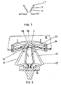
- Figure 1 shows a cup 1 which is 105 mm in open end diameter and 65 mm deep and which has been stretch-formed from an 0.8 mm thick sheet of crystalline polypropylene.
- Cup 1 is essentially frustro-conical in shape having approximately circular base 2 and an outwardly sloping side wall 3.
- the perimeter of base 2 is marked by short thin blobs 4 of virtually unstretched plastics material which are 1 mm wide, extend 5 mm radially inwardly of the perimeter and stand 0.5 mm proud of the adjacent surface of base 2.
- Blobs 4 are spaced equally apart by doubly radiussed scallops 5 consisting of orthogonally radiussed curves such as curves 6 and 7 as shown in Figures 2 and 3 respectively.
- Side wall 3 consists of slightly concave longitudinal contiguous panels 8 and longitudinal ribs 9 each of which extends from a blob 4 along the boundary between a pair of contiguous panels 8. Ribs 9 are composed of virtually unstretched material and are therefore thicker than panels 8. Side wall 3 terminates in a stepped out rim 10 carrying an accurately stamped flange 11 to which a suitably rimmed lid may be snap-fitted.
- the crystalline polypropylene of base 2 is uniaxially orientated in directions radial of base 2 and has a good and controlled uniformity of thickness.
- the crystalline polypropylene of panels 8 is biaxially orientated in the longitudinal and circumferential directions and the circumferential orientation confers improved hoop strength on cup 1.
- the crystalline polypropylene of panels 8 has a good and controlled uniformity of thickness.
- Ribs 9 help to resist vertical crushing forces when several cups 1 are stacked. Cup 1 can be made using the method and apparatus illustrated by Figures 4 to 9 except that for simplicity Figures 4 to 7 show only four blades.
- Figure 4 shows a stretching tool 12 comprising blades 13 and thrust rod 14 positioned below a heat-softened and therefore slightly dished sheet 15 of crystalline polypropylene.
- Sheet 15 is held against substantial non-stretching movement by retractable opposed clamping rings 16A and 16B held stationary by rigid supports 17.
- Stretching tool 12 has an array of eighteen (only three shown) pairs of rotatable opposed neighbouring cranked blades 13 disposed along the diagonals of a rectangular polyhedron.
- Each blade 13 has a cold tip 18 (as shown in Figure 8) located at the end of a cold knife edge 19. Knife-edge 19 is shown in Figure 9.
- Each blade 13 is rotatable about a pivot 20 mounted on thrust rod 14. Blades 13 are lightly biassed by springs 21 to a central position against stops 22 such that in the central position each pivot 20 remains inboard of the locus of unseparated tips 18. Rotation of blades 13 against the bias separates each tip 18 and each knife edge 19 both radially outwardly and also circumferentially from its neighbours.
- a primary movement vertically upwards of tool 12 presses cold tips 18 against under-face 23 of sheet 15 and chills blobs 4 of polypropylene against which tips 18 press. Blobs 4 are then able to resist puncture by tips 18.
- Further primary movement of tool 12 imparts an upwards initial stretch to portion 24 of sheet 15 outboard of tips 18 and creates saddles 25 as shown in Figure 5. So far virtually no stretching of portion 26 of sheet 15 inboard of saddles 25 occurs.
- Initial stretching generates an increasing tension in outboard portion 24 and consequently an increasing reaction is exerted on tips 18.
- the increasing reaction on each tip 18 applies an increasing moment (or leverage) to blade 13 which is counter to the biassing moment from spring 21.
- knife edges 19 come into contact with outboard portion 24 and create and chill ridges 9 enabling them to receive and transmit circumferential stretching and orientating forces from knife edges 19 as dilation proceeds.
- the circumferential stretching is again in a direction transverse to that of the primary movement of tool 12.
- knife edges 19 (which are slanted) impose their slant on ribs 9 and so and so exert a positive control on the shape of side wall 3 and in particular they reduce its tendency to bow inwardly.
- Blades 13 are provided with protruding heels 27 which co-operate with a corresponding rebate 28 in top clamping ring 16A to impress a stepped out rim 10 into the extremity of outboard portion 24.
- Sheet 15 turns under clamping ring 16A where it remains virtually unstretched and thick. On allowing sheet 15 to cool, the thicker portion between rings 16 becomes very rigid and permits accurate stamping which frees the stretch-formed cup from sheet 15 and creates a flange 11 for receiving a snap- fitting lid.
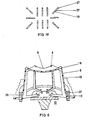
- Figure 10 shows an array of six pairs of opposed blades 13 for making a rectangular cup.
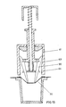
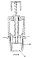
- Figure 11 shows a 0.8 mm thick heat-softened polypropylene sheet 30 clamped onto rim 31 of cavity mould 32 by clamping ring 33 which prevents non-stretching movement of sheet 30.
- apparatus for stretching sheet 30 comprising a stretching tool having thirty-six cold tips 34 (only two shown) each located to one end of a 1 mm thick steel blade 35 rotatably mounted on flanged end 36 of a spindle 37 whose flanged end 36 is housed within a hollow cylindrical guide 38.
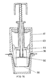
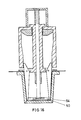
- Spindle 37 is slidable in a central annular bearing 39 so that it can be advanced further into guide 38 to give tips 36 a primary movement which presses them against sheet 30 causing initial stretching as shown in Figure 13.
- Tips 34 are biassed to their central position shown in Figure 11 by springs (not shown) acting on blades 35.
- the springs also bias ends 40 of blades 35 remote from tips 36 against internal surface 41 of guide 38 and initially this bias is assisted by chamfered edge 42 of bearing 39 which also urges ends 40 against internal surface 41.
- the apparatus shown in Figure 11 additionally comprises bell-headed plunger 48 slidably mounted in spindle 37 and terminating in radially extending plate 49 having cold sharp dependent circumferential rim 50.
- plate 49 contains apertures 51 to allow free passage of plate 49 relative to blades 35.
- Plunger 48 is initially spaced from spindle 37 by spring 52 reacting between stop 45 and bell-head 53. Total separation of spindle 37 and plunger 50 is prevented by stop 45A formed on plunger 50.
- the polyhedral cross-section of the cup can be made more circular by an outwards dilation of the longitudinal panels 52A to meet the circle defined by the locus of the ribs 52 so reducing the prominence of the ribs 52 to produce a cup suited to printing by resilient mat transfer processes.
- the cup can be further dilated to produce a more circumferentially orientated product having better hoop strength at the cost of thinning the ribs and reducing their crush resistance.
- Figures 19 and 20 illustrate the stretch-forming of a sheet 57 by opposed groups of stretching tools 58 and 59 arranged so that tools 58 are staggered relative to tools 59.
- tools 58 and 59 are spaced apart to allow insertion of sheet 57 between them and then their primary movements cause them to press against sheet 57 whereupon it is held against non-stretching movements without the need to employ separate holding means.
- Primary movement in unison of tools 58 and 59 causes them to interpenetrate and when tools 58 and 59 have interpenetrated sufficiently to clear each other, their tips 60 (shown prior to separation in dashed lines) are separated to dilate initially stretched sheet 57 to form cups 62 as shown in Figure 20.
- rims 63 of cups 62 can be mutually overhanging as shown in Figure 19 so allowing a greater number of cups 62 to be formed from a given area of sheet 57.
- the method illustrated by Figures 19 and 20 is especially suitable for use on sheets of crystalline polypropylene arriving in-line from a slit extrusion die via a stack of polishing rolls. Production rates of over 100,000 cups per hour are expected to be possible.
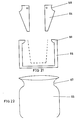
- Figure 21 shows modified apparatus for forming a jar 66 shown in Figure 22 having an undercutting neck 67.
- the apparatus is modified by the provision of curved rebates 68 on blades 64 and re-entrant annular flange 69 on mould 65 which co-operates with rebates 68 to define neck 67.
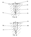
- FIG. 23 An alternative method of stretch forming hollow articles is indicated in Figures 23 and 24.
- a cold hollow needle 70 having along its side an aperture 71 is given a primary movement which presses its cold tip 72 against a heat-softened sheet 80 of thermoplastic stretched across the open top of a bottle-shaped cavity mould 73.
- Needle 70 is maintained at a temperature 50°C below the crystalline melting point of the thermoplastics, and, where it contacts sheet 80, a small blob 74 of unstretched thermoplastics material is formed. As the needle 70 penetrates into mould 73, blob 74 is pushed along in front of needle 70 thereby initially stretching sheet 80.
- a plate 75 is slidably attached around the needle 70 at such a location that when the blob 74 approaches the bottom of mould 73, plate 75 seals the open end of mould 73 across sheet 80. Compressed air is then blown through hollow needle 70 as it advances further through the plate 75 and air emerges through the aperture 71 to dilate initially stretched sheet into contact with internal surface 76 of mould 73. On cooling, the resultant moulding can be removed.
- the moulding is a bottomless bottle, the walls of which are biaxially orientated and which can be conveniently filled through the open bottom and then sealed to provide a product ready for sale.
- a suitable polypropylene for making cups illustrated in the drawings has a melt flow index of 1.5 g/10 minutes and is a sequential copolymer of propylene with 13% (by weight of the copolymer) of ethylene made by injecting ethylene into the closing stages of an otherwise homopolymerisation of propylene.
- the sheet polypropylene is heated to a temperature of 160°C and the tips and knife-edges of the stretching tools are heated to 100°C.
- a plain polystyrene cup weighing 14.95 g and having a wall thickness varying between 0.5 mm and 0.3 mm was tested and found to have a crush load of 37 kg.
- a ribbed cup according to the present invention, weighing 14.75 g but otherwise identical had a crush load of 42 kg, i.e. 13% greater.
- a tool as illustrated in Figure 10 was fitted in place of the usual draper plug on a "Kaberit" thermoforming machine.
- a top die comprising a vented mould for 500 ml cups was left unchanged.
- the tool was approximately i mm smaller in depth and opened diameter than the vented cavity. Cups were formed at 17 cycles/minute compared to the usual commercial speed of 11 cycles/minute. The following savings were measured:
- the minimum number of twelve tips specified for a stretching tool having separable tips is directed to cups of conventional size or larger. For smaller cups, a smaller number of tips may be used provided that each tip is less than ten times the average thickness of the ribs (or blob if no ribs are present) from its neighbouring tip.
Landscapes
- Engineering & Computer Science (AREA)
- Mechanical Engineering (AREA)
- Blow-Moulding Or Thermoforming Of Plastics Or The Like (AREA)
- Shaping By String And By Release Of Stress In Plastics And The Like (AREA)
Priority Applications (1)
| Application Number | Priority Date | Filing Date | Title |
|---|---|---|---|
| AT79300869T ATE10457T1 (de) | 1978-05-18 | 1979-05-18 | Verfahren und vorrichtung zum stempelstreckformen von tiefgezogenen hohlkoerpern aus thermoplastischem kunststoff. |
Applications Claiming Priority (8)
| Application Number | Priority Date | Filing Date | Title |
|---|---|---|---|
| AUPD443378 | 1978-05-18 | ||
| AU4433/78 | 1978-05-18 | ||
| AUPD483378 | 1978-06-22 | ||
| AU4833/78 | 1978-06-22 | ||
| AU8263/79 | 1979-04-03 | ||
| AUPD826379 | 1979-04-03 | ||
| AUPD839879 | 1979-04-17 | ||
| AU8398/79 | 1979-04-17 |
Publications (3)
| Publication Number | Publication Date |
|---|---|
| EP0006682A2 true EP0006682A2 (fr) | 1980-01-09 |
| EP0006682A3 EP0006682A3 (en) | 1980-09-17 |
| EP0006682B1 EP0006682B1 (fr) | 1984-11-28 |
Family
ID=27424114
Family Applications (1)
| Application Number | Title | Priority Date | Filing Date |
|---|---|---|---|
| EP79300869A Expired EP0006682B1 (fr) | 1978-05-18 | 1979-05-18 | Procédé et appareil pour l'emboutissage au moyen d'un poinçon d'articles creux en matière thermoplastique |
Country Status (8)
| Country | Link |
|---|---|
| US (1) | US4288401A (fr) |
| EP (1) | EP0006682B1 (fr) |
| DE (1) | DE2967310D1 (fr) |
| DK (1) | DK159910C (fr) |
| HK (1) | HK49388A (fr) |
| IE (1) | IE49576B1 (fr) |
| NZ (1) | NZ190442A (fr) |
| SG (1) | SG101987G (fr) |
Cited By (5)
| Publication number | Priority date | Publication date | Assignee | Title |
|---|---|---|---|---|
| FR2576009A1 (fr) * | 1985-01-17 | 1986-07-18 | Schott Glaswerke | Procede pour ameliorer la planeite de feuilles |
| DE3929826C1 (fr) * | 1989-09-07 | 1990-04-19 | Schmalbach-Lubeca Ag, 3300 Braunschweig, De | |
| WO1995001255A1 (fr) * | 1993-07-02 | 1995-01-12 | Tetra Laval Holdings & Finance S.A. | Emballage aplatissable |
| CN107692880A (zh) * | 2017-11-07 | 2018-02-16 | 宁波爱满格母婴科技有限公司 | 一种辅食机 |
| US10465973B2 (en) | 2002-02-25 | 2019-11-05 | BSH Hausgeräte GmbH | Inner part for a refrigerating device |
Families Citing this family (11)
| Publication number | Priority date | Publication date | Assignee | Title |
|---|---|---|---|---|
| JPS6056547A (ja) * | 1983-09-08 | 1985-04-02 | 株式会社クラレ | 耐亀裂性に優れた包装容器 |
| US5523046A (en) * | 1984-05-22 | 1996-06-04 | The Family Trust U/T/A | Method of using a female tool with movable plates to form a sheet of material into a flower pot or flower pot cover having outward fins |
| US5573789A (en) * | 1984-05-22 | 1996-11-12 | Southpac Trust International, Inc. | Apparatus having blades and plates for forming sheet material into a flower pot cover having outward fins |
| JPH0615204B2 (ja) * | 1987-05-28 | 1994-03-02 | しげる工業株式会社 | 真空成形装置 |
| US5637330A (en) * | 1995-06-07 | 1997-06-10 | Samsonite Corporation | Apparatus for differential pressure forming shells for hard sided luggage containers |
| TW311896B (fr) * | 1995-06-07 | 1997-08-01 | Elliot Younessian | |
| US5755311A (en) * | 1995-06-07 | 1998-05-26 | Samsonite Corporation | Differential pressure formed luggage with molded integrated frame |
| US6264050B1 (en) | 1998-10-06 | 2001-07-24 | Plastipak Packaging, Inc. | Container with improved neck portion and method for making the same |
| DE20319530U1 (de) * | 2003-12-16 | 2004-02-26 | Marbach Werkzeugbau Gmbh | Thermoformwerkzeug |
| FR2947475B1 (fr) * | 2009-07-01 | 2011-08-19 | Arcil | Piston de positionnement d'un decor de pot alimentaire dans un moule, dispositif et procede associes |
| JP6385612B2 (ja) | 2016-03-02 | 2018-09-05 | 三菱電機株式会社 | マルチビーム衛星通信システム |
Citations (11)
| Publication number | Priority date | Publication date | Assignee | Title |
|---|---|---|---|---|
| FR1214895A (fr) * | 1958-08-26 | 1960-04-12 | Comptoir Des Prod Chim Ind | Procédé et dispositif pour la fabrication de corps creux en matière plastique |
| FR1238800A (fr) * | 1959-07-06 | 1960-08-19 | Hoechst Ag | Procédé d'étirage ou d'emboutissage profond et guidé pour la fabrication de corps creux en matières synthétiques thermoplastiques |
| GB860810A (en) * | 1957-01-22 | 1961-02-08 | Ici Australia Ltd | Method and apparatus for the production of hollow articles |
| US2974366A (en) * | 1957-11-08 | 1961-03-14 | Applied Plastics Inc | Method and machine for forming articles from plastic sheet material |
| US3078025A (en) * | 1961-05-10 | 1963-02-19 | Illinois Tool Works | Sheet formed molded articles |
| NL299923A (nl) * | 1962-10-31 | 1965-08-25 | Alpenlandisches Kunststoffwerk | Oprekinrichting voor een slangeinde |
| FR1419876A (fr) * | 1964-10-23 | 1965-12-03 | Barville Ets | Perfectionnements aux récipients souples ou semi-rigides et à leur mise en oeuvre |
| US3420930A (en) * | 1963-12-17 | 1969-01-07 | Continental Can Co | Method of drawing cup-shaped articles |
| FR2124903A5 (en) * | 1971-01-28 | 1972-09-22 | Panontin Mario | Open-cell dimpled plates - for use as wallboards etc |
| DE2118841B1 (de) * | 1971-04-19 | 1973-05-17 | Erich 7141 Grossbottwar Blattert | Aus Kunststoff gespritzter Hohl korper, insbesondere Becher, Blumentopf oder dgl |
| FR2278469A1 (fr) * | 1973-12-03 | 1976-02-13 | Dow Chemical Co | Poincon de formage de matieres thermoplastiques et procede de fabrication de corps creux en comportant l'utilisation |
Family Cites Families (10)
| Publication number | Priority date | Publication date | Assignee | Title |
|---|---|---|---|---|
| US3256564A (en) * | 1961-05-10 | 1966-06-21 | Illinois Tool Works | Apparatus for fabricating sheet formed molded articles |
| US3341893A (en) * | 1963-09-23 | 1967-09-19 | Illinois Tool Works | Apparatus for forming double thickness fins in a thin wall plastic container |
| US3578735A (en) * | 1968-12-30 | 1971-05-11 | Monsanto Co | Method and apparatus for molding plastic articles |
| US3947205A (en) * | 1973-01-31 | 1976-03-30 | Illinois Tool Works Inc. | Apparatus for forming non-nestable containers |
| US4088718A (en) * | 1973-02-23 | 1978-05-09 | Mulvany Jr R F | Method for forming involute plastic articles from thermoplastic sheet material |
| US4118454A (en) * | 1975-09-02 | 1978-10-03 | Sumitomo Bakelite Company Limited | Method for producing transparent plastic molded articles |
| IT1053243B (it) * | 1975-10-09 | 1981-08-31 | Omv Spa | Sistema di produzione di oggetti cavi finiti picavati da un nastro di materiale plastico per termo formatura |
| US4075266A (en) * | 1976-11-01 | 1978-02-21 | Friedrich Theysohn | Method for coating foil material |
| DE2652172C3 (de) * | 1976-11-16 | 1980-09-18 | Erich 7141 Steinheim Blattert | Spritzgießform zum Herstellen eines aus Kunststoff gespritzten, folienstarken Hohlkörpers |
| GB1593311A (en) * | 1977-03-30 | 1981-07-15 | Shell Int Research | Making cupped articles from mixed polyolefin plastics sheet |
-
1979
- 1979-05-14 NZ NZ190442A patent/NZ190442A/xx unknown
- 1979-05-18 DK DK205379A patent/DK159910C/da not_active IP Right Cessation
- 1979-05-18 US US06/040,312 patent/US4288401A/en not_active Expired - Lifetime
- 1979-05-18 EP EP79300869A patent/EP0006682B1/fr not_active Expired
- 1979-05-18 DE DE7979300869T patent/DE2967310D1/de not_active Expired
- 1979-08-08 IE IE972/79A patent/IE49576B1/en not_active IP Right Cessation
-
1987
- 1987-11-18 SG SG1019/87A patent/SG101987G/en unknown
-
1988
- 1988-07-07 HK HK493/88A patent/HK49388A/xx not_active IP Right Cessation
Patent Citations (11)
| Publication number | Priority date | Publication date | Assignee | Title |
|---|---|---|---|---|
| GB860810A (en) * | 1957-01-22 | 1961-02-08 | Ici Australia Ltd | Method and apparatus for the production of hollow articles |
| US2974366A (en) * | 1957-11-08 | 1961-03-14 | Applied Plastics Inc | Method and machine for forming articles from plastic sheet material |
| FR1214895A (fr) * | 1958-08-26 | 1960-04-12 | Comptoir Des Prod Chim Ind | Procédé et dispositif pour la fabrication de corps creux en matière plastique |
| FR1238800A (fr) * | 1959-07-06 | 1960-08-19 | Hoechst Ag | Procédé d'étirage ou d'emboutissage profond et guidé pour la fabrication de corps creux en matières synthétiques thermoplastiques |
| US3078025A (en) * | 1961-05-10 | 1963-02-19 | Illinois Tool Works | Sheet formed molded articles |
| NL299923A (nl) * | 1962-10-31 | 1965-08-25 | Alpenlandisches Kunststoffwerk | Oprekinrichting voor een slangeinde |
| US3420930A (en) * | 1963-12-17 | 1969-01-07 | Continental Can Co | Method of drawing cup-shaped articles |
| FR1419876A (fr) * | 1964-10-23 | 1965-12-03 | Barville Ets | Perfectionnements aux récipients souples ou semi-rigides et à leur mise en oeuvre |
| FR2124903A5 (en) * | 1971-01-28 | 1972-09-22 | Panontin Mario | Open-cell dimpled plates - for use as wallboards etc |
| DE2118841B1 (de) * | 1971-04-19 | 1973-05-17 | Erich 7141 Grossbottwar Blattert | Aus Kunststoff gespritzter Hohl korper, insbesondere Becher, Blumentopf oder dgl |
| FR2278469A1 (fr) * | 1973-12-03 | 1976-02-13 | Dow Chemical Co | Poincon de formage de matieres thermoplastiques et procede de fabrication de corps creux en comportant l'utilisation |
Cited By (9)
| Publication number | Priority date | Publication date | Assignee | Title |
|---|---|---|---|---|
| FR2576009A1 (fr) * | 1985-01-17 | 1986-07-18 | Schott Glaswerke | Procede pour ameliorer la planeite de feuilles |
| GB2171093A (en) * | 1985-01-17 | 1986-08-20 | Zeis Stiftung Schott Glaswerke | Process for improving the surface finish of foils |
| DE3929826C1 (fr) * | 1989-09-07 | 1990-04-19 | Schmalbach-Lubeca Ag, 3300 Braunschweig, De | |
| US5080853A (en) * | 1989-09-07 | 1992-01-14 | Schmalbach-Lubeca Ag | Process for deep drawing plastic foils |
| WO1995001255A1 (fr) * | 1993-07-02 | 1995-01-12 | Tetra Laval Holdings & Finance S.A. | Emballage aplatissable |
| AU676925B2 (en) * | 1993-07-02 | 1997-03-27 | Tetra Laval Holdings & Finance Sa | Collapsible package |
| US10465973B2 (en) | 2002-02-25 | 2019-11-05 | BSH Hausgeräte GmbH | Inner part for a refrigerating device |
| CN107692880A (zh) * | 2017-11-07 | 2018-02-16 | 宁波爱满格母婴科技有限公司 | 一种辅食机 |
| CN107692880B (zh) * | 2017-11-07 | 2024-03-29 | 宁波爱满格母婴科技有限公司 | 一种辅食机 |
Also Published As
| Publication number | Publication date |
|---|---|
| IE790972L (en) | 1979-11-18 |
| DE2967310D1 (en) | 1985-01-10 |
| EP0006682B1 (fr) | 1984-11-28 |
| NZ190442A (en) | 1983-06-17 |
| DK205379A (da) | 1979-11-19 |
| EP0006682A3 (en) | 1980-09-17 |
| DK159910B (da) | 1990-12-31 |
| DK159910C (da) | 1991-05-21 |
| HK49388A (en) | 1988-07-15 |
| US4288401A (en) | 1981-09-08 |
| SG101987G (en) | 1989-06-16 |
| IE49576B1 (en) | 1985-10-30 |
Similar Documents
| Publication | Publication Date | Title |
|---|---|---|
| EP0006682A2 (fr) | Procédé et appareil pour l'emboutissage au moyen d'un poinçon d'articles creux en matière thermoplastique | |
| US3290418A (en) | Method and mold for making thinwalled containers | |
| US3240851A (en) | Method and apparatus for severing thermoplastic material | |
| US4388356A (en) | Heat setting a thermoformed PET article utilizing a male plug as a constraint | |
| US4048781A (en) | Process for the production of a product filled container | |
| US4477243A (en) | Thermoforming apparatus | |
| US3218379A (en) | Process and apparatus for forming plastic cups or the like | |
| US3964237A (en) | Apparatus for the production of a product filled container | |
| US3901640A (en) | Expandable forming plug | |
| EP0072832A1 (fr) | Formation par allongement d'articles creux a partir d'une feuille thermoplastique | |
| USRE23171E (en) | Apparatus fob and method of | |
| GB971160A (en) | Thin-wall containers of thermoplastic materials | |
| ES348130A1 (es) | Un metodo de conformar articulos huecos por trabajo en frio. | |
| US3746497A (en) | Apparatus for making articles of manufacture from a thin film of plastic | |
| GB1090615A (en) | Methods and apparatus for forming necked containers from thermoplastic sheet material | |
| US3244779A (en) | Selective heating and drawing of plastics | |
| US3450807A (en) | Thermoplastic sheet formation | |
| EP0579737B1 (fr) | Production de profiles en polymere a orientation biaxiale | |
| US3837517A (en) | Molecularly oriented hollow article, such as a bottle | |
| US3381068A (en) | Thermoforming and scoring method and apparatus | |
| WO1983001412A1 (fr) | Ameliorations relatives a des recipients | |
| US4252518A (en) | Vacuum forming machine | |
| CA1135020A (fr) | Procede pour le faconnage des matieres thermoplastiques | |
| JPH0375337B2 (fr) | ||
| EP0201303A2 (fr) | Moule, machine et procédé de thermoformage |
Legal Events
| Date | Code | Title | Description |
|---|---|---|---|
| PUAI | Public reference made under article 153(3) epc to a published international application that has entered the european phase |
Free format text: ORIGINAL CODE: 0009012 |
|
| AK | Designated contracting states |
Designated state(s): AT BE CH DE FR GB IT LU NL SE |
|
| PUAL | Search report despatched |
Free format text: ORIGINAL CODE: 0009013 |
|
| 17P | Request for examination filed | ||
| AK | Designated contracting states |
Designated state(s): AT BE CH DE FR GB IT LU NL SE |
|
| ITF | It: translation for a ep patent filed | ||
| GRAA | (expected) grant |
Free format text: ORIGINAL CODE: 0009210 |
|
| AK | Designated contracting states |
Designated state(s): AT BE CH DE FR GB IT LU NL SE |
|
| REF | Corresponds to: |
Ref document number: 10457 Country of ref document: AT Date of ref document: 19841215 Kind code of ref document: T |
|
| REF | Corresponds to: |
Ref document number: 2967310 Country of ref document: DE Date of ref document: 19850110 |
|
| ET | Fr: translation filed | ||
| PLBE | No opposition filed within time limit |
Free format text: ORIGINAL CODE: 0009261 |
|
| STAA | Information on the status of an ep patent application or granted ep patent |
Free format text: STATUS: NO OPPOSITION FILED WITHIN TIME LIMIT |
|
| 26N | No opposition filed | ||
| ITTA | It: last paid annual fee | ||
| EPTA | Lu: last paid annual fee | ||
| EAL | Se: european patent in force in sweden |
Ref document number: 79300869.9 |
|
| REG | Reference to a national code |
Ref country code: GB Ref legal event code: 732E |
|
| NLS | Nl: assignments of ep-patents |
Owner name: TETRA LAVAL HOLDINGS & FINANCE S.A.;HITEK LIMITED |
|
| BECA | Be: change of holder's address |
Free format text: 960917 *TETRA LAVAL HOLDINGS & FINANCE S.A.:AVENUE GENERAL GUISAN 70, 1009 PULLY |
|
| BECH | Be: change of holder |
Free format text: 960917 *TETRA LAVAL HOLDINGS & FINANCE S.A. |
|
| PGFP | Annual fee paid to national office [announced via postgrant information from national office to epo] |
Ref country code: SE Payment date: 19980420 Year of fee payment: 20 Ref country code: FR Payment date: 19980420 Year of fee payment: 20 |
|
| PGFP | Annual fee paid to national office [announced via postgrant information from national office to epo] |
Ref country code: DE Payment date: 19980421 Year of fee payment: 20 |
|
| PGFP | Annual fee paid to national office [announced via postgrant information from national office to epo] |
Ref country code: AT Payment date: 19980422 Year of fee payment: 20 |
|
| PGFP | Annual fee paid to national office [announced via postgrant information from national office to epo] |
Ref country code: GB Payment date: 19980427 Year of fee payment: 20 |
|
| PGFP | Annual fee paid to national office [announced via postgrant information from national office to epo] |
Ref country code: NL Payment date: 19980430 Year of fee payment: 20 |
|
| PGFP | Annual fee paid to national office [announced via postgrant information from national office to epo] |
Ref country code: CH Payment date: 19980506 Year of fee payment: 20 |
|
| PGFP | Annual fee paid to national office [announced via postgrant information from national office to epo] |
Ref country code: BE Payment date: 19980513 Year of fee payment: 20 |
|
| REG | Reference to a national code |
Ref country code: FR Ref legal event code: TP |
|
| PG25 | Lapsed in a contracting state [announced via postgrant information from national office to epo] |
Ref country code: SE Free format text: LAPSE BECAUSE OF NON-PAYMENT OF DUE FEES Effective date: 19980519 |
|
| PGFP | Annual fee paid to national office [announced via postgrant information from national office to epo] |
Ref country code: LU Payment date: 19980526 Year of fee payment: 20 |
|
| BE20 | Be: patent expired |
Free format text: 19990518 *TETRA LAVAL HOLDINGS & FINANCE S.A. |
|
| PG25 | Lapsed in a contracting state [announced via postgrant information from national office to epo] |
Ref country code: GB Free format text: LAPSE BECAUSE OF NON-PAYMENT OF DUE FEES Effective date: 19990517 Ref country code: CH Free format text: LAPSE BECAUSE OF EXPIRATION OF PROTECTION Effective date: 19990517 |
|
| PG25 | Lapsed in a contracting state [announced via postgrant information from national office to epo] |
Ref country code: NL Free format text: LAPSE BECAUSE OF EXPIRATION OF PROTECTION Effective date: 19990518 Ref country code: LU Free format text: LAPSE BECAUSE OF EXPIRATION OF PROTECTION Effective date: 19990518 Ref country code: AT Free format text: LAPSE BECAUSE OF EXPIRATION OF PROTECTION Effective date: 19990518 |
|
| REG | Reference to a national code |
Ref country code: GB Ref legal event code: PE20 Effective date: 19990517 |
|
| REG | Reference to a national code |
Ref country code: CH Ref legal event code: PL |
|
| NLV7 | Nl: ceased due to reaching the maximum lifetime of a patent |
Effective date: 19990518 |
|
| EUG | Se: european patent has lapsed |
Ref document number: 79300869.9 |