EP0006437A1 - Method and device for adjusting and correcting the aberrations of an electrooptical condensor in a microprojector - Google Patents
Method and device for adjusting and correcting the aberrations of an electrooptical condensor in a microprojector Download PDFInfo
- Publication number
- EP0006437A1 EP0006437A1 EP79101503A EP79101503A EP0006437A1 EP 0006437 A1 EP0006437 A1 EP 0006437A1 EP 79101503 A EP79101503 A EP 79101503A EP 79101503 A EP79101503 A EP 79101503A EP 0006437 A1 EP0006437 A1 EP 0006437A1
- Authority
- EP
- European Patent Office
- Prior art keywords
- condenser
- field diaphragm
- ring field
- lens system
- beam path
- Prior art date
- Legal status (The legal status is an assumption and is not a legal conclusion. Google has not performed a legal analysis and makes no representation as to the accuracy of the status listed.)
- Granted
Links
Images
Classifications
-
- H—ELECTRICITY
- H01—ELECTRIC ELEMENTS
- H01J—ELECTRIC DISCHARGE TUBES OR DISCHARGE LAMPS
- H01J37/00—Discharge tubes with provision for introducing objects or material to be exposed to the discharge, e.g. for the purpose of examination or processing thereof
- H01J37/02—Details
- H01J37/04—Arrangements of electrodes and associated parts for generating or controlling the discharge, e.g. electron-optical arrangement, ion-optical arrangement
- H01J37/153—Electron-optical or ion-optical arrangements for the correction of image defects, e.g. stigmators
-
- H—ELECTRICITY
- H01—ELECTRIC ELEMENTS
- H01J—ELECTRIC DISCHARGE TUBES OR DISCHARGE LAMPS
- H01J37/00—Discharge tubes with provision for introducing objects or material to be exposed to the discharge, e.g. for the purpose of examination or processing thereof
- H01J37/02—Details
- H01J37/21—Means for adjusting the focus
-
- H—ELECTRICITY
- H01—ELECTRIC ELEMENTS
- H01J—ELECTRIC DISCHARGE TUBES OR DISCHARGE LAMPS
- H01J37/00—Discharge tubes with provision for introducing objects or material to be exposed to the discharge, e.g. for the purpose of examination or processing thereof
- H01J37/30—Electron-beam or ion-beam tubes for localised treatment of objects
- H01J37/3002—Details
- H01J37/3007—Electron or ion-optical systems
Definitions
- the invention relates to a method and a device for focus adjustment and error correction of an electron-optical condenser in a microprojector, which is used to image a large-area transmission mask on a wafer by means of an electron-optical imaging system, the mask being illuminated with a bundle of rays of axis-parallel electron beams generated by the condenser.
- the necessary distance can be roughly determined by calculating or measuring the focal length.
- the lens errors and field distortions due to external influences such as magnetic materials distributed asymmetrically to the outer axis, must also be corrected by stigmators. A complete computation of these errors is not possible.
- the condenser lens field would have to be measured directly in the microprojector at its place of use, which would only be possible with great technical effort and without the required accuracy.
- the invention is therefore based on the object of specifying a method by means of which the focus setting and error correction of the condenser can be checked quickly and at any time in the microprojector using simple means and, if necessary, corrected.
- This object is achieved in that the imaging system is switched off, that instead of the mask, a ring field diaphragm is introduced into the beam path and that by changing the focal length of the condenser and / or by changing the settings of stigmators, the image of the ring field diaphragm resulting from shadow projection in a plane below the imaging system is adjusted in size and shape of the ring field diaphragm.
- An advantage of this method is that no intervention in the condenser is necessary. Instead of measuring the field symmetry and the focal length exactly, a simple shadow projection of a ring shutter aperture is carried out.
- the electron beams In the case of an error-corrected condenser, in whose front focal plane the electron source is located, the electron beams would all leave the condenser parallel to the axis. The shadow projection would then result in a 1: 1 image of the ring field diaphragm.
- the real diameter of the silhouette is therefore a measure of the deviation of the focus setting from the target setting.
- the angular deviation of the electron beam must only be approximately 2 ⁇ 10 -5 rad. This means that the location of the silhouette at 1 m from the ring field blends must be accurate to 20 ⁇ m.
- the focal length can be changed until the focus setting is correct.
- the roundness of the silhouette in turn is a measure of the correction state of the condenser lens.
- the rotational symmetry of the condenser lens field can also be optimized by changing the excitation of the stigmators assigned to this lens.
- the radius R of the ring field diaphragm is approximately equal to the radius of the mask used.
- the registration device used in the device is preferably formed from a photo plate. After developing the photo plate, the resulting image can be measured well and compared with the ring field diaphragm shown. A number of exposures may be required to set the condenser optimally.
- the registration device consists of a detector arrangement.
- the entire image plane can be covered by individual detectors. A specific location of the image plane is assigned to each detector.
- the image of the ring field diaphragm can be reconstructed from the signals from the detectors, which are illuminated in the shadow projection.
- the detector arrangement consists of a plurality of detectors arranged on a circle with the radius R, the signals of which are fed to a control element, which generates signals for automatic correction of the condenser focal length and / or stigmator setting.
- a control element which generates signals for automatic correction of the condenser focal length and / or stigmator setting.
- an automatic control device is created, the Kon The sensor and stigmator settings are changed until all detectors on the circle are illuminated. It is thus achieved that the electron beams passing through the ring field diaphragm run axially parallel.
- a particularly simple check of the condenser setting and error correction results with an annular disk-shaped detector arrangement, via which the image of the ring field diaphragm is guided in at least two directions by means of a deflection system that is usually present in the imaging lens system.
- the detector signals are fed to a control element which, by comparing the signals during the deflection in different directions, generates a signal for correcting the condenser focal length and / or stigmator setting.
- the deflection directions are preferably orthogonal to one another. The shape and size of the silhouette can be derived from the signal profiles generated in this way.
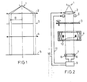
- Figure 1 shows schematically the beam path of the microprojector during focus adjustment and error correction.
- Figure 2 shows the basic structure of the micro projector with the device according to the invention.
- 1 denotes the electron source and 2 the condenser.
- the condenser will consist of a single electron-optical lens. Usually, however, is a multi-stage lens system provided.
- Below the condenser is an annular field diaphragm 3 with an average radius R. The ring width is negligibly small compared to this radius.
- the switched-off imaging lens 4 (or a corresponding imaging lens system) is also shown, which has no influence on the beam path.
- An electromagnetic deflection system 12 (FIG. 2) is located in the imaging lens, of which only the coils required for a deflection direction are shown. In order to be able to deflect the electron beams in all directions, at least one further pair of coils is necessary.
- a level 5 in which, for example, a photo plate is located, the silhouette of the ring field diaphragm 3 is registered. This image is compared in size and shape with the ring field diaphragm. If, for example, the diameter of the image is smaller than that of the diaphragm 3, the distance of the source 1.
- FIG. 2 shows the basic structure of the micro projector with an automatic correction device.
- the arrangement of the electron source 1, the condenser 2 and the imaging lens 4 corresponds to that of FIG. 1.
- additional stigmators 6 are indicated below the condenser 2, additional stigmators 6 are indicated.
- the ring field diaphragm 3 is rotatably mounted so that it can be pivoted out of the beam path during the imaging of a transmission mask, not shown here.
- a detector arrangement 7, which consists of a plurality of detectors 8 arranged on a circle with the radius R, serves as the registration device.
- the outputs of all detectors 8 are fed to a control element 9.
- This control element generates an output signal 10 and 11 for the correction of the condenser focal length and / or the stigmator setting.
Abstract
Die Erfindung betrifft ein Verfahren und eine Vorrichtung zur Fokuseinstellung und Fehlerkorrektur eines elektronenoptischen Kondensors in einem Mikroprojektor. Erfindungsgemäss wird in den Strahlengang zwischen die Kondensorlinse (2) und das abgeschaltete Abbildungslinsensystem (4) eine Ringfeldblende (3) eingeschwenkt und durch Schattenprojektion in eine Ebene unterhalb des Abbildungslinsensystems (4) abgebildet. Die Brennweite der Kondensorlinse (2) und die Einstellung von Stigmatoren (6), die dieser Linse zugeordnet sind, wird so lange verandert, bis das Schattenbild in Grösse und Form der Ringfeldblende (3) entspricht. Die die Kondensorlinse (2) verlassenden Strahlen verlaufen dann achsparallel. Das Verfahren kann im Mikroprojektor insbesondere nach jeder Inbetriebnahme zur Einstellung des Beleuchtungsstrahlenganges wiederholt werden.The invention relates to a method and a device for focus adjustment and error correction of an electron optical condenser in a micro projector. According to the invention, an annular field diaphragm (3) is pivoted into the beam path between the condenser lens (2) and the switched-off imaging lens system (4) and is projected onto a plane below the imaging lens system (4) by shadow projection. The focal length of the condenser lens (2) and the setting of stigmators (6) that are assigned to this lens are changed until the silhouette corresponds in size and shape to the ring field diaphragm (3). The rays leaving the condenser lens (2) then run parallel to the axis. The process can be repeated in the micro projector, in particular after each start-up, in order to set the illumination beam path.
Description
Die Erfindung betrifft ein Verfahren und eine Vorrichtung zur Fokuseinstellung und Fehlerkorrektur eines elektronenoptischen Kondensors in einem Mikroprojektor, der zur Abbildung einer großflächigen Transmissionsmaske auf einen Wafer mittels eines elektronenoptischen abbildungssystems dient, wobei die Maske mit einem durch den Kondensor erzeugten Strahlenbündel achsparalleler Elektronenstrahlen beleuchtet wird.The invention relates to a method and a device for focus adjustment and error correction of an electron-optical condenser in a microprojector, which is used to image a large-area transmission mask on a wafer by means of an electron-optical imaging system, the mask being illuminated with a bundle of rays of axis-parallel electron beams generated by the condenser.
Für die Herstellung hochintegrierter Schaltkreise werden ,in einem Mikroprojektor großflächige Transmissionsmasken verkleinert auf einen sogenannten Wafer, z. B. eine einkristalline Siliziumscheibe, abgebildet. In der Prozessfolge müssen bei nacheinander durchgeführten Belichtungen einzelne Strukturdetails paßgerecht aufeinander gefügt werden. Mit fortschreitender Miniaturisierung wachsen dabei die Anforderungen an das Abbildungs- und Beleuchtungssystem. Besonders kritisch ist die richtige Einstellung des Kondensors, um eine möglichst achsparallele Beleuchtung der Maske zu erhalten. Dazu muß die Elektronenquelle des Mikroprojektors exakt in der vorderen Brennebene des Kondensors liegen.For the manufacture of highly integrated circuits, large-area transmission masks are reduced to a so-called wafer, e.g. B. a single-crystal silicon wafer is shown. In the process sequence, individual structural details must be matched to one another when exposures are carried out successively. With increasing miniaturization awake the requirements for the imaging and lighting system. Correct setting of the condenser is particularly critical in order to obtain the most parallel possible illumination of the mask. To do this, the electron source of the microprojector must lie exactly in the front focal plane of the condenser.
Durch Berechnen oder Messen der Brennweite läßt sich der notwendige Abstand in etwa ermitteln. Neben diesem Abstand müssen auch die Linsenfehler und Feldverzerrungen infolge äußerer Einflüsse, wie unsymmetrisch zur äußeren Achse verteilte magnetische Materialien,durch Stigmatoren korrigiert werden. Eine vollständige rechnerische Erfassung dieser Fehler ist nicht möglich. Ein Ausmessen des Kondensorlinsenfeldes müßte direkt im Mikroprojektor an seinem Einsatzort vorgenommen werden, was nur mit großem technischem Aufwand und ohne die erforderliche Genauigkeit durchführbar wäre.The necessary distance can be roughly determined by calculating or measuring the focal length. In addition to this distance, the lens errors and field distortions due to external influences, such as magnetic materials distributed asymmetrically to the outer axis, must also be corrected by stigmators. A complete computation of these errors is not possible. The condenser lens field would have to be measured directly in the microprojector at its place of use, which would only be possible with great technical effort and without the required accuracy.
Der Erfindung liegt daher die Aufgabe zugrunde, ein Verfahren anzugeben, mit dessen Hilfe die Fokuseinstellung und Fehlerkorrektur des Kondensors direkt im Mikroprojektor mit einfachen Mitteln schnell und jederzeit wiederholbar überprüft und gegebenenfalls korrigiert werden kann. Diese Aufgabe wird erfindungsgemäß dadurch gelöst, daß das Abbildungssystem abgeschaltet wird, daß anstelle der Maske eine Ringfeldblende in den Strahlengang eingebracht wird und daß durch Brennweitenänderung des Kondensors und/oder durch Einstelländerungen von Stigmatoren das durch Schattenprojektion in einer Ebene unterhalb des Abbildungssystems entstehende Bild der Ringfeldblende in Größe und Form der Ringfeldblende angepaßt wird.The invention is therefore based on the object of specifying a method by means of which the focus setting and error correction of the condenser can be checked quickly and at any time in the microprojector using simple means and, if necessary, corrected. This object is achieved in that the imaging system is switched off, that instead of the mask, a ring field diaphragm is introduced into the beam path and that by changing the focal length of the condenser and / or by changing the settings of stigmators, the image of the ring field diaphragm resulting from shadow projection in a plane below the imaging system is adjusted in size and shape of the ring field diaphragm.
Ein Vorteil dieses Verfahrens besteht darin, daß keine Eingriffe in den Kondensor nötig sind. Anstatt die Feldsymmetrie und die Brennweite exakt auszumessen, wird eine einfache Schattenprojektion einer Ringfaldblende durchgeführt. Bei einem fehlerkorrigierten Kondensor, in dessen vorderer Brennebene sich die Elektronenquelle befindet, würden die Elektronenstrahlen den Kondensor alle achsparallel verlassen. Die Schattenprojektion ergäbe dann eine 1 : 1 Abbildung der Ringfeldblende. Der wirkliche Durchmesser des Schattenbildes ist daher ein Maß für die Abweichung der Fokuseinstellung von der Solleinstellung. Um beispielsweise eine Kantenlagegenaugikeit von 0,1 /µm zu erhalten, darf die Winkelabweichung des Elektronenstrahls nur etwa 2 x 10⁻⁵ rad betragen. Das bedeutet, daß die Ortsbestimmung des Schattenbildes in 1 m Entfernung von der Ringfeldblends auf 20 um genau sein muß. Beispielsweise durch Änderung der Erregung bei einer magnetischen Kondensorlinse kann die Brennweite so lange geändert werden, bis die Fokuseinstellung stimmt.An advantage of this method is that no intervention in the condenser is necessary. Instead of measuring the field symmetry and the focal length exactly, a simple shadow projection of a ring shutter aperture is carried out. In the case of an error-corrected condenser, in whose front focal plane the electron source is located, the electron beams would all leave the condenser parallel to the axis. The shadow projection would then result in a 1: 1 image of the ring field diaphragm. The real diameter of the silhouette is therefore a measure of the deviation of the focus setting from the target setting. In order to obtain an edge position accuracy of 0.1 / µm, for example, the angular deviation of the electron beam must only be approximately 2 × 10 -5 rad. This means that the location of the silhouette at 1 m from the ring field blends must be accurate to 20 µm. For example, by changing the excitation of a magnetic condenser lens, the focal length can be changed until the focus setting is correct.
Die Rundheit des Schattenbildes wiederum ist ein Maß für den Korrekturzustand der Kondensorlinse. Durch Erregungsänderung der dieser Linse zugeordneten Stigmatoren kann auch die Rotationssymmetrie des Kondensorlinsenfeldes optimiert werden.The roundness of the silhouette in turn is a measure of the correction state of the condenser lens. The rotational symmetry of the condenser lens field can also be optimized by changing the excitation of the stigmators assigned to this lens.
Damit das erfindungsgemäße Verfahren möglichst einfach durchgeführt werden kann, empfiehlt es sich, im Mikroprojektor eine zwischen den Kondensor und das Linsensystem schwenkbare Ringfeldblende sowie eine etwa in der Ebene des Wafers in den Strahlengang einbringbare Registriereinrichtung zur Aufnahme des Schattenbildes vorzusehen. Bereits diese zwei Mittel genügen, um die Fokuseinstellung und die Rotationssymmetrie zu überprüfen.So that the method according to the invention can be carried out as simply as possible, it is advisable to provide in the microprojector a ring field diaphragm which can be pivoted between the condenser and the lens system and a registration device which can be introduced into the beam path approximately in the plane of the wafer to record the silhouette. These two means alone are sufficient to check the focus setting and the rotational symmetry.
Da die Linsenfehler mit wachsendem Achsabstand größer werden, ist es besonders wichtig, eine.korrekte Beleuchtung für diesen Bereich, also den Bildfeldrand, sicherzustellen.As the lens errors increase with increasing center distance, it is particularly important to ensure correct lighting for this area, i.e. the edge of the image field.
In Weiterbildung der Erfindung ist daher vorgesehen, daß der Radius R der Ringfeldblende etwa gleich dem Radius der verwendeten Maske ist.In a development of the invention it is therefore provided that the radius R of the ring field diaphragm is approximately equal to the radius of the mask used.
Die in der Vorrichtung verwendete Registriereinrichtung wird vorzugsweise aus einer Fotoplatte gebildet. Nach dem Entwickeln der Fotoplatte läßt sich das entstandene Bild gut ausmessen und mit der abgebildeten Ringfeldblende vergleichen. Für eine optimale Einstellung des Kondensors sind unter Umständen eine Reihe von Aufnahmen nötig.The registration device used in the device is preferably formed from a photo plate. After developing the photo plate, the resulting image can be measured well and compared with the ring field diaphragm shown. A number of exposures may be required to set the condenser optimally.
In einer weiteren vorteilhaften Ausgestaltung der erfindungsgemäßen Vorrichtung besteht die Registriereinrichtung aus einer Detektoranordnung. Dabei kann die ganze Bildebene von Einzeldetektoren bedeckt sein. Jedem Detektor ist ein bestimmter Ort der Bildebene zugeordnet. Aus den Signalen der Detektoren, die bei der Schattenprojektion beleuchtet werden, kann das Bild der Ringfeldblende rekonstruiert werden.In a further advantageous embodiment of the device according to the invention, the registration device consists of a detector arrangement. The entire image plane can be covered by individual detectors. A specific location of the image plane is assigned to each detector. The image of the ring field diaphragm can be reconstructed from the signals from the detectors, which are illuminated in the shadow projection.
Die mit der Detektoranordnung erzielbaren Vorteile kommen besonders dann zum Ausdruck, wenn die Detektoranordnung aus einer Mehrzahl auf einem Kreis mit dem Radius R angeordneter Detektoren besteht, deren Signale einem Steuerglied zugefuhrt sind, das daraus Signale zur automatischen Korrektur der Kondensorbrennweite und/oder Stigmatoreinstellung erzeugt. Auf diese Weise ist eine automatische Regeleinrichtung geschaffen, die die Kondensor- und Stigmatoreinstellung so lange verändert, bis alle Detektoren auf dem Kreis beleuchtet sind. Damit ist erreicht, daß die die Ringfeldblende durchsetzenden Elektronenstrahlen achsparallel verlaufen.The advantages that can be achieved with the detector arrangement are particularly evident when the detector arrangement consists of a plurality of detectors arranged on a circle with the radius R, the signals of which are fed to a control element, which generates signals for automatic correction of the condenser focal length and / or stigmator setting. In this way, an automatic control device is created, the Kon The sensor and stigmator settings are changed until all detectors on the circle are illuminated. It is thus achieved that the electron beams passing through the ring field diaphragm run axially parallel.
Eine besonders einfache Überprüfung der Kondensoreinstellung und Fehlerkorrektur ergibt sich mit einer ringscheibenförmigen Detektoranordnung, über die das Bild der Ringfeldblende mittels eines üblicherweise im Abbildungslinsensystem vorhandenen Ablenksystems in mindestens zwei Richtungen geführt wird. Die Detektorsignale werden einem Steuerglied zugeführt, das durch Vergleich der Signale während der Ablenkung in unterschiedlichen Richtungen ein Signal zur Korrektur der Kondensorbrennweite und/oder Stigmatoreinstellung erzeugt. Vorzugsweise werden die Ablenkrichtungen orthogonal zueinander liegen. Die Form und Größe des Schattenbildes lassen sich aus den so erzeugten Signalverläufen ableiten.A particularly simple check of the condenser setting and error correction results with an annular disk-shaped detector arrangement, via which the image of the ring field diaphragm is guided in at least two directions by means of a deflection system that is usually present in the imaging lens system. The detector signals are fed to a control element which, by comparing the signals during the deflection in different directions, generates a signal for correcting the condenser focal length and / or stigmator setting. The deflection directions are preferably orthogonal to one another. The shape and size of the silhouette can be derived from the signal profiles generated in this way.
Anhand zweier Figuren wird im folgenden das erfindungsgemäße Verfahren und die Vorrichtung beschrieben und erläutert.The method and the device according to the invention are described and explained below with reference to two figures.
Dabei zeigt Figur 1 schematisch den Strahlengang des Mikroprojektors bei der Fokuseinstellung und Fehlerkorrektur.Figure 1 shows schematically the beam path of the microprojector during focus adjustment and error correction.
Figur 2 zeigt den prinzipiellen Aufbau des Mikroprojektors mit der erfindungsgemäßen Vorrichtung.Figure 2 shows the basic structure of the micro projector with the device according to the invention.
Bei beiden Figuren sind für gleiche Teile gleiche Bezugszeichen verwendet worden.In both figures, the same reference numerals have been used for the same parts.
In Figur 1 ist mit 1 die Elektronenquelle und mit 2 der Kondensor bezeichnet. Der Kondensor wird im einfachsten Fall aus einer einzigen elektronenoptischen Linse bestehen. Üblicherweise jedoch ist ein mehrstufiges Linsensystem vorgesehen. Unterhalb des Kondensors befindet sich eine Ringfeldblende 3 mit einem mittleren Radius R. Die Ringbreite ist gegen diesen Radius vernachläßigbar klein.In Figure 1, 1 denotes the electron source and 2 the condenser. In the simplest case, the condenser will consist of a single electron-optical lens. Usually, however, is a multi-stage lens system provided. Below the condenser is an
Der Vollständigkeit halber ist auch die abgeschaltete Abbildungslinse 4 (oder ein entsprechendes Abbildungslinsensystem) dargestellt, die ohne Einfluß auf den Strahlengang ist. In der Abbildungslinse befindet sich ein elektromagnetisches Ablenksystem 12 (Fig. 2), von dem nur die für eine Ablenkrichtung erforderlichen Spulen dargestellt sind. Um die Elektronenstrahlen in alle Richtungen ablenken zu können, ist mindestens noch ein weiteres Spulenpaar nötig. In einer Ebene 5, in der sich beispielsweise eine Fotoplatte befindet, wird das Schattenbild der Ringfeldblende 3 registriert. Dieses Bild wird in Größe und Form mit der Ringfeldblende verglichen. Ist beispielsweise der Durchmesser des Bildes kleiner als der der Blende 3, so ist der Abstand der Quelle 1 .vom Kondensor 2 größer als die Brennweite des Kondensors 2,und das den Kondensor verlassende Strahlenbündel ist konvergent. Die-Erregung des Kondensors muß in diesem Fallherabgesetzt werden, bis die damit verbundene Brennweitenvergrößerung ausreicht, um Brennebene und Quelle 1 zusammenfallenzulassen.For the sake of completeness, the switched-off imaging lens 4 (or a corresponding imaging lens system) is also shown, which has no influence on the beam path. An electromagnetic deflection system 12 (FIG. 2) is located in the imaging lens, of which only the coils required for a deflection direction are shown. In order to be able to deflect the electron beams in all directions, at least one further pair of coils is necessary. In a
Anstelle der Erregungsänderung wäre auch eine mechanische Verschiebung des Kondensors entlang der optischen Achse denkbar, wegen der Größe und dem Gewicht dürfte das jedoch technisch nur mit größtem Aufwand zu realisieren sein.Instead of the change in excitation, a mechanical displacement of the condenser along the optical axis would also be conceivable, however, due to the size and weight, this should only be technically feasible with great effort.
Figur 2 zeigt den prinzipiellen Aufbau des Mikroprojektors mit einer automatischen Korrekturvorrichtung. Die Anordnung der Elektronenquelle 1, des Kondensors 2 und der Abbildungslinse 4 entspricht der der Figur 1. Unterhalb des Kondensors 2 sind zusätzliche Stigmatoren 6 angedeutet. Die Ringfeldblende 3 ist drehbar gelagert, so daß sie während der Abbildung einer hier nicht dargestellten Transmissionsmaske aus dem Strahlengang herausgeschwenkt werden kann. Als Registriereinrichtung dient in diesem Ausführungsbeispiel eine Detektoranordnung 7, die aus einer Mehrzahl auf einem Kreis mit dem Radius R angeordneter Detektoren 8 besteht.Die Ausgänge aller Detektoren 8 sind einem Steuerglied 9 zugeführt. Dieses Steuerglied erzeugt je ein Ausgangssignal 10 und 11 für die Korrektur der Kondensorbrennweite und/oder die Stigmatoreinstellung.Figure 2 shows the basic structure of the micro projector with an automatic correction device. The The arrangement of the
Claims (7)
Applications Claiming Priority (2)
| Application Number | Priority Date | Filing Date | Title |
|---|---|---|---|
| DE2827086 | 1978-06-16 | ||
| DE2827086A DE2827086C2 (en) | 1978-06-16 | 1978-06-16 | Method for adjusting the focus and correcting errors in an electron-optical condenser in a microprojector and microprojector for carrying out the method |
Publications (2)
| Publication Number | Publication Date |
|---|---|
| EP0006437A1 true EP0006437A1 (en) | 1980-01-09 |
| EP0006437B1 EP0006437B1 (en) | 1981-08-26 |
Family
ID=6042289
Family Applications (1)
| Application Number | Title | Priority Date | Filing Date |
|---|---|---|---|
| EP79101503A Expired EP0006437B1 (en) | 1978-06-16 | 1979-05-16 | Method and device for adjusting and correcting the aberrations of an electrooptical condensor in a microprojector |
Country Status (4)
| Country | Link |
|---|---|
| US (1) | US4238680A (en) |
| EP (1) | EP0006437B1 (en) |
| JP (1) | JPS551100A (en) |
| DE (1) | DE2827086C2 (en) |
Families Citing this family (3)
| Publication number | Priority date | Publication date | Assignee | Title |
|---|---|---|---|---|
| JPS59115527A (en) * | 1982-12-22 | 1984-07-04 | Toshiba Corp | Electron beam transfer device |
| US5821542A (en) * | 1996-06-26 | 1998-10-13 | International Business Machines Corporation | Particle beam imaging system having hollow beam illumination |
| US9801551B2 (en) * | 2012-07-20 | 2017-10-31 | Intuitive Sugical Operations, Inc. | Annular vision system |
Citations (3)
| Publication number | Priority date | Publication date | Assignee | Title |
|---|---|---|---|---|
| DE760410C (en) * | 1941-02-11 | 1953-10-05 | Aeg | Use of a catcher arranged in a microscope for focusing |
| DE2515549B1 (en) * | 1975-04-09 | 1976-09-09 | Siemens Ag | Electron microscope with mask imaging on specimen - has projection lens system with specified quotients of magnetic lenses |
| DE2515550B1 (en) * | 1975-04-09 | 1976-10-07 | Siemens Ag | Electron microscope for mask imaging - has electrostatic condenser lens energised via voltage divider in response to acceleration voltage |
Family Cites Families (2)
| Publication number | Priority date | Publication date | Assignee | Title |
|---|---|---|---|---|
| US3745358A (en) * | 1971-05-10 | 1973-07-10 | Radiant Energy Systems | Alignment method and apparatus for electron projection systems |
| DE2722958A1 (en) * | 1977-05-20 | 1978-11-23 | Siemens Ag | METHOD FOR ADJUSTING A SEMICONDUCTOR DISC RELATIVE TO A RADIATION MASK IN X-RAY PHOTOLITHOGRAPHY |
-
1978
- 1978-06-16 DE DE2827086A patent/DE2827086C2/en not_active Expired
-
1979
- 1979-05-16 EP EP79101503A patent/EP0006437B1/en not_active Expired
- 1979-05-17 US US06/039,878 patent/US4238680A/en not_active Expired - Lifetime
- 1979-06-14 JP JP7512479A patent/JPS551100A/en active Pending
Patent Citations (3)
| Publication number | Priority date | Publication date | Assignee | Title |
|---|---|---|---|---|
| DE760410C (en) * | 1941-02-11 | 1953-10-05 | Aeg | Use of a catcher arranged in a microscope for focusing |
| DE2515549B1 (en) * | 1975-04-09 | 1976-09-09 | Siemens Ag | Electron microscope with mask imaging on specimen - has projection lens system with specified quotients of magnetic lenses |
| DE2515550B1 (en) * | 1975-04-09 | 1976-10-07 | Siemens Ag | Electron microscope for mask imaging - has electrostatic condenser lens energised via voltage divider in response to acceleration voltage |
Also Published As
| Publication number | Publication date |
|---|---|
| US4238680A (en) | 1980-12-09 |
| DE2827086C2 (en) | 1980-07-24 |
| DE2827086B1 (en) | 1979-11-08 |
| EP0006437B1 (en) | 1981-08-26 |
| JPS551100A (en) | 1980-01-07 |
Similar Documents
| Publication | Publication Date | Title |
|---|---|---|
| AT393925B (en) | ARRANGEMENT FOR IMPLEMENTING A METHOD FOR POSITIONING THE IMAGE OF THE STRUCTURE ON A MASK TO A SUBSTRATE, AND METHOD FOR ALIGNING MARKERS ARRANGED ON A MASK ON MARKINGS ARRANGED ON A CARRIER | |
| DE69233508T2 (en) | An image forming apparatus and method for manufacturing micro devices | |
| DE69730903T2 (en) | Exposure method and apparatus | |
| DE69631260T2 (en) | Scanning exposure apparatus, exposure method using the same, and method of manufacturing the device | |
| WO2017153165A1 (en) | Method for producing an illumination system for an euv projection exposure system, and illumination system | |
| DE2702445C3 (en) | Corpuscular beam optical device for reducing the image of a mask onto a specimen to be irradiated | |
| EP0002668B1 (en) | Optical distance measuring apparatus | |
| DE3642418A1 (en) | PROJECTION EXPOSURE DEVICE | |
| DE3342719C2 (en) | Positioning device in a projection imagesetter | |
| WO2004031854A2 (en) | Illumination system for a wavelength = 193 nm, comprising sensors for determining the illumination | |
| EP0019721A1 (en) | Optical projection apparatus for aligning a projection image on a surface | |
| DE102007047446A1 (en) | Optical element with at least one electrically conductive region and illumination system with such an element | |
| DE102008040742A1 (en) | Method and device for monitoring multi-mirror arrangements, optical arrangement with such a device and with a second multiple mirror arrangement for switching on and off a first multiple mirror arrangement and illumination optics for a projection exposure apparatus with such a device | |
| DE2512468C2 (en) | "Electron microscope with a Wien filter as an energy analyzer" | |
| DE2717531C2 (en) | Device for focusing an optical system on a target focal plane | |
| EP0069823A1 (en) | Process and apparatus for the mutual positioning (registration) of objects in X-ray and ion beam lithography | |
| EP0231164B1 (en) | Device for ion-projection apparatuses | |
| DE2702444C3 (en) | Corpuscular beam optical device for imaging a mask on a specimen | |
| DE102017219179B3 (en) | Method of restoring an illumination system for an EUV system, detector module and method for monitoring a lighting system installed in an EUV system | |
| EP0006437B1 (en) | Method and device for adjusting and correcting the aberrations of an electrooptical condensor in a microprojector | |
| DE10024634B4 (en) | Electron beam exposure device and method | |
| DE2555781C3 (en) | Electron beam apparatus | |
| EP0006985B1 (en) | Method and device for the determination of the focal length of electrooptical lenses of long focal length | |
| DE2515550C2 (en) | BODY RAY OPTICAL DEVICE FOR IMAGING A MASK ON A PREPARATION TO BE IRRADIATED | |
| EP0051567B1 (en) | Apparatus for the automatic adjustment of at least one object |
Legal Events
| Date | Code | Title | Description |
|---|---|---|---|
| PUAI | Public reference made under article 153(3) epc to a published international application that has entered the european phase |
Free format text: ORIGINAL CODE: 0009012 |
|
| AK | Designated contracting states |
Designated state(s): FR GB NL |
|
| 17P | Request for examination filed | ||
| GRAA | (expected) grant |
Free format text: ORIGINAL CODE: 0009210 |
|
| AK | Designated contracting states |
Designated state(s): FR GB NL |
|
| PGFP | Annual fee paid to national office [announced via postgrant information from national office to epo] |
Ref country code: FR Payment date: 19820517 Year of fee payment: 4 |
|
| PGFP | Annual fee paid to national office [announced via postgrant information from national office to epo] |
Ref country code: NL Payment date: 19820531 Year of fee payment: 4 |
|
| PG25 | Lapsed in a contracting state [announced via postgrant information from national office to epo] |
Ref country code: NL Effective date: 19831201 |
|
| GBPC | Gb: european patent ceased through non-payment of renewal fee | ||
| NLV4 | Nl: lapsed or anulled due to non-payment of the annual fee | ||
| PG25 | Lapsed in a contracting state [announced via postgrant information from national office to epo] |
Ref country code: FR Free format text: LAPSE BECAUSE OF NON-PAYMENT OF DUE FEES Effective date: 19840131 |
|
| REG | Reference to a national code |
Ref country code: FR Ref legal event code: ST |
|
| PG25 | Lapsed in a contracting state [announced via postgrant information from national office to epo] |
Ref country code: GB Effective date: 19881118 |
|
| PLBE | No opposition filed within time limit |
Free format text: ORIGINAL CODE: 0009261 |
|
| STAA | Information on the status of an ep patent application or granted ep patent |
Free format text: STATUS: NO OPPOSITION FILED WITHIN TIME LIMIT |